Page is loading ...

PRINTED IN U.S.A.
RITE-HITE PRINT SHOP
RHH50 High Capacity
Dock Leveler
Installation Manual
PUBLICATION NO. 1287
RITE-HITE PART NO. 0128927
MARCH 2014
part of the SMOOTH TRANSITION DOK SYSTEMTM
This Manual Covers Dock Levelers Built After Serial Numbers:
10EH030001M and up
MADE IN U.S.A.

2Pub. No. 1287 - March 2014
RITE-HITE®RHH50 Dock Leveler Installation Manual
TABLE OF CONTENTS
NOTICE TO USER . . . . . . . . . . . . . . . . . . . . . . . . . . . . . . . . . . . . . . . . . . . . . . . . . . . . . . . . . . . . . . . . . . . . . . . . . .2
SAFETY WARNINGS . . . . . . . . . . . . . . . . . . . . . . . . . . . . . . . . . . . . . . . . . . . . . . . . . . . . . . . . . . . . . . . . . . . . . . . .3
INSTALLATION INSTRUCTIONS . . . . . . . . . . . . . . . . . . . . . . . . . . . . . . . . . . . . . . . . . . . . . . . . . . . . . . . . . . . . . . .6
SHIMMING DETAIL . . . . . . . . . . . . . . . . . . . . . . . . . . . . . . . . . . . . . . . . . . . . . . . . . . . . . . . . . . . . . . . . . . . . . . . . .9
BUMPER INSTALLATION . . . . . . . . . . . . . . . . . . . . . . . . . . . . . . . . . . . . . . . . . . . . . . . . . . . . . . . . . . . . . . . . . . .12
LIP SUPPORT INSTALLATION . . . . . . . . . . . . . . . . . . . . . . . . . . . . . . . . . . . . . . . . . . . . . . . . . . . . . . . . . . . . . . .13
ELECTRICAL INSTALLATION . . . . . . . . . . . . . . . . . . . . . . . . . . . . . . . . . . . . . . . . . . . . . . . . . . . . . . . . . . . . . . . .14
LEVELER LUBRICATION . . . . . . . . . . . . . . . . . . . . . . . . . . . . . . . . . . . . . . . . . . . . . . . . . . . . . . . . . . . . . . . . . . . .20
LEVELER ADJUSTMENTS . . . . . . . . . . . . . . . . . . . . . . . . . . . . . . . . . . . . . . . . . . . . . . . . . . . . . . . . . . . . . . . . . .21
RITE-HITE WARRANTY . . . . . . . . . . . . . . . . . . . . . . . . . . . . . . . . . . . . . . . . . . . . . . . . . . . . . . . . . . .BACK COVER
PRODUCT SPECIFIC WARRANTY
Rite-Hite warrants the RHH50 Dock Leveler for five-years parts and one-year labor from date of shipment in
accordance with Rite-Hite's Standard Warranty Policy.
NOTICE TO USER
Your local Rite-Hite®representative provides a Planned Maintenance Program (P.M.P.) which can be fitted to your
specific operation. Call your local representative or Rite-Hite®at 414-355-2600.
The Rite-Hite products in this manual are covered by one or more of the following U.S. patents: 5,546,623;
5,553,987; 5,582,498; 5,664,930; 5,702,223; 5,762,459 (RE: 37,570); 5,882,167; 6,065,172; 6,070,283; 6,085,375;
6,089,544; 6,092,970; 6,106,212; 6,116,839; 6,190,109; 6,276,016; 6,311,352; 6,318,947; 6,322,310; 6,360,394;
6,368,043; 6,431,819; 6,488,464; 6,499,169; 6,505,713; 6,520,472; 6,524,053; 6,634,049; 6,726,432; 6,773,221;
6,832,403; 6,880,301; 7,032,267; 7,062,814; 7,134,159; 7,213,285; 7,216,391; 7,363,670; 7,380,305; 7,503,089;
7,533,431; 7,546,655; 7,584,517; 7,681,271; 7,823,239; 7,841,823; 7,877,831; 7,914,042; 8,006,811; 8,065,770;
8,141,189; 8,191,194; 8,286,757; 8,287,223; 8,303,235; 8,307,956; 8,443,474; 8,464,384; 8,464,846; 8,465,245 and
pending U.S and foreign patent applications. RITE-HITE®, THINMANTM, SAFE-T-LIP®, HYDRACHEK®, WHEEL-LOKTM,
DOK-LOK®, DUAL-DOK®, SAFE-T-STRUTTM, DOK-COMMANDER®, JUMBOTM, HYDRA-RITETM, SAFE-T-GATE®, RITE-
VUTM LIGHT COMMUNICATION SYSTEM and SMOOTH TRANSITION DOK SYSTEMTM, are trademarks of Rite-Hite®.

Pub. No. 1287 - March 2014 3
RITE-HITE®RHH50 Dock Leveler Installation Manual
SAFETY WARNING
LOCKOUT/TAGOUT PROCEDURES
The Occupational Safety and Health Administration (OSHA) requires, in addition to posting safety warnings and barri-
cading the work area (including, but not limited to, trucking office and loading docks), that the power supply has been
locked in the OFF position or disconnected. It is mandatory that an approved lockout device is utilized. An example of
a lockout device is illustrated. The proper lockout procedure requires that the person responsible for the repairs is the
only person who has the ability to remove the lockout device.
In addition to the lockout device, it is also a requirement to tag the power control in a manner that will clearly note that
repairs are under way and state who is responsible for the lockout condition. Tagout devices have to be constructed
and printed so that exposure to weather conditions, or wet and damp locations, will not cause the tag to deteriorate or
become unreadable.
Rite-Hite does not recommend any particular lockout device, but recommends the utilization of an OSHA approved
device (refer to OSHA regulation 1910.147). Rite-Hite also recommends the review and implementation of an entire
safety program for the Control of Hazardous Energy (Lockout/Tagout). These regulations are available through OSHA
publication 3120.
When working with electrical or electronic con-
trols, make sure that the power source has been
locked out and tagged out according to OSHA
regulations and approved local electrical codes.
XXXXXXXXXXXX
XXXXXXXXXXX
OPERATE
DO NOT
FIGURE 1 - LOCKOUT/TAGOUT
This is a statement of serious hazard. Failure to
follow the listed instructions could place the
individual at risk of serious injury or death.
This is the highest level statement. Failure to
follow the listed instructions will most likely
result in severe injury or death.
The statements used with this level of warning
deal with a safe operating procedure. If the pro-
cedure is ignored the possibility of personal
injury may exist.
IMPORTANT is used to draw attention to a pro-
cedure that needs to be followed to prevent
machine damage.

4Pub. No. 1287 - March 2014
RITE-HITE®RHH50 Dock Leveler Installation Manual
OTHER IMPORTANT OPERATIONAL SAFETY WARNINGS
Never be under the dock leveler platform or lip
without:
• Installing the Safe-T-StrutTM or other
supporting device.
• If lip needs to be extended, follow
procedures shown under Safety Devices on
the following page.
• Turning off power to the control box.
• Locking out and tagging out the main
power source, as shown under Safety
Warnings on preceding page.
Always barricade the dock leveler at ground
level and dock level from any form of traffic
when maintenance is required.
Inspect the dock leveler monthly to ensure that
there are no broken or worn parts which could
cause injury to personnel or damage to the
equipment.
• Before starting installation or maintenance,
check and follow the safety procedures of
the facility where the dock leveler is being
installed.
• Never enter a truck/trailer until its brakes are
set, air has been dumped from air ride
suspension (if applicable), and you have
visually inspected to be sure truck/trailer is
securely held in place by a vehicle restraint
or wheel chock per OSHA regulations.
• Never operate the leveler with you, anyone,
or anything on, or in front of the leveler, or
without a truck/trailer parked in position, or
from on the truck/trailer bed.
• DO NOT operate with anyone under platform
or in front of the lip.
• When leveler is not in use, always store it so
that it is supported by the lip supports and
that it is level with the surrounding dock
floor.
• If a malfunction does occur, always call your
authorized Rite-Hite service representative
immediately.

Pub. No. 1287 - March 2014 5
RITE-HITE®RHH50 Dock Leveler Installation Manual
SAFETY DEVICES RITE-HITE LEVELERS
• Post warnings and barricades at dock level
and at drive level to indicate that work is
being done around and under the leveler
platform.
• Lockout/Tagout power to the leveler and post
warnings when work is being performed on
the leveler.
Never be under the dock leveler platform or lip
without:
• Installing the Safe-T-Struttm. See below right.
This can be done with the assistance of
another person by:
- Raise leveler until platform reaches its
highest position and lip extends.
Continue to maintain this position.
- Then have assistant insert the smaller end
of the Safe-T-StrutTM through the hole in
the middle of the leveler lip and place the
strut’s wider open end over the base
located on the leveler’s front frame. Align
the holes on the base and the Safe-T-
StrutTM so that the leveler may be secured
with the retaining pin and safety clip.
- Release the push button on powered
levelers allowing the Safe-T-StrutTM to rest
on the underside of the lip.
• Lockout/Tagout power supply.
- Turn off the power to the control box.
- Lockout/tagout the main power source, as
shown under Safety Warnings on the
inside front cover of this manual.
- Always barricade the leveler at dock level
and drive level to prevent any
unauthorized use of the leveler.
Remove the Maintenance Support.
• For Safe-T-StrutTM removal, have an
assistant raise the leveler to its highest
position with lip fully extended. Release the
safety clip and remove retaining pin. Lift strut
off base, and remove from lip. Return the
Safe-T-StrutTM to the proper storage position.
• If you are unable to install the Maintenance
Support properly, contact your authorized
Rite-Hite Service Representative or Rite-Hite
Customer Service at 1-414-355-2600.
FIGURE 2 - INSTALL SAFE-T-STRUTTM SUPPORT

PREPARATION PRIOR TO INSTALLATION
1. Check pit to insure it meets pit details. If pit does not
match pit details, contact your local representative or
Rite-Hite before proceeding.
NOTE: Unit may not operate properly if pit is not
correct.
2. Leave shipping bands on leveler until instructed to
remove them.
3. Verify that leveler voltage matches the voltage
supplied at pit, and that proper electrical junction box
or weatherproof outlet has been installed.
4. Clean out pit and remove all debris from work area.
INSTALLATION PROCEDURES
1. Handling plates must be inserted into the forward
handling holes of the toe guards. See Figure 3 and 4.
2. Attach lifting chain, lift leveler and position above pit.
Lower leveler into pit. See Figure 4.
6Pub. No. 1287 - March 2014
RITE-HITE®RHH50 Dock Leveler Installation Manual
INSTALLATION INSTRUCTIONS
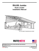
FIGURE 3 - HANDLING PLATE
2”
DIA.
3”
1-1/2”
3/4”
8”
Flat
3 -1/2”
1-3/4”
Threaded Rod,
1” Dia. x 2” LG.
Nut,
1” Dia.
Flat,
3/8” x 3” x 8”
Hard Rolled Steel
1-1/2”
15º
2 required, Supplied by others.
Lifting Chain
Handling Plate
Top Of Leveler
Shipping Bands
Lip
Platform Assy.
Front Frame Angle
Frame
Front Curb Angle
Dock Face Pit Floor
Side Curb Angle
Rear Curb Angle
Dock Floor
Handling Plate
Toe guard
Rear Transition
Plate
Nut
FIGURE 4 - PLACEMENT OF LEVELER
See Step #3

3. Center leveler in pit so that equal gaps are
maintained on each side of the leveler. See Figure 5.
4. Push leveler straight back until the front frame angle
is flush with the front curb angle. If the pit is not
square, push leveler straight back until the front
frame angle is completely behind the front curb angle
by no more than 1/4 inch. The front frame angle
should never extend past the front curb angle.
NOTES:
a. If the leveler cannot be pushed back far enough, the
back edge of the rear transition plate can be cut off
up to 1 inch. If trimming the back edge of angle does
not allow frame to be positioned properly in pit,
contact your local representative or Rite-Hite for
assistance. Check the area between the rear
transition plate and the back of the pit. If a gap exists,
place spacers between the rear transition plate and
the rear curb angle. Tack weld spacers to the rear
transition plate only. See Figure 6 and 7.
b. Minimum electrode must be 1/8", 7018 or better.
Pub. No. 1287 - March 2014 7
RITE-HITE®RHH50 Dock Leveler Installation Manual
INSTALLATION INSTRUCTIONS (Continued)
TOP VIEW OF
LEVELER IN PIT
Equal gaps must be
maintained on each side
of the leveler.
Rear edge of leveler frame must be against rear
curb angle. Shim or trim rear transition plate as
necessary. If pit is not square, See Figure 6.
C
L
FIGURE 5 - LEVELER PLACEMENT
One Inch
Maximum Cut
FIGURE 6 - TRIM TRANSITION PLATE
FIGURE 7 - REAR FRAME SPACERS
Frame must be in contact with
rear curb angle
Fill gap between rear
transition plate and
rear curb angle
behind hinge lugs.
Spacer must span
distance from outside
to outside of hinge
lugs
Fill gap between rear
transition plate and
rear curb angle on
each end with a 3
inch long spacer.
2 places
each spacer
as necessary.
1/4” Tack
Equal gaps
must be
maintained on
each side of
leveler.
C
L

5. Remove lifting chain from handling plates.
6. Lift front frame of leveler until platform is level with
dock floor. Cut and place shims under below dock
stops, ramp cylinder clevis and maintenance support
base located on front frame angle. Tack shims
together and to front frame angle. See Figure 8 & 9.
NOTE: For levelers with 20 inch lips, lift bottom of
front frame angle until it is at 23-1/2 inches (or 19-1/2
inches or for a 20” frame) below dock floor, and add
shims. See Figure 8 & 9.
7. Remove and discard all shipping bands.
8. Place a mark on the face of the front frame angle to
indicate the frame centerline. Also, place a mark on
the face of the lip to indicate the lip/platform
centerline.
9. Shift the front frame angle sideways so that the frame
centerline matches up with the lip/platform centerline
(using the lines drawn earlier). Once frame and
platform have been centered in the pit, tack weld the
front frame angle and shims to the front curb angle.
10. Manually raise platform and extend lip on powered
levelers. Install maintenance support.
11. Remove handling plates from platform.
12. Lift rear frame of leveler until platform is level with
dock floor. Cut and place shims under the rear frame
support posts. Tack shims together and to rear frame
channel. See Figure 8 & 9.
IMPORTANT: Insure all shims are in place at this
time. Tack shims together and to frame. See
Figure 8 & 9.
8Pub. No. 1287 - March 2014
RITE-HITE®RHH50 Dock Leveler Installation Manual
INSTALLATION INSTRUCTIONS (Continued)
• ALWAYS ground to the frame or front pit
angle when welding. DO NOT ground welding
equipment to any electrical components. DO
NOT ground to leveler platform when welding
on leveler frame. Damage to bearings or
electrical components may result.
• DO NOT connect green ground lead into
control box or junction box until all welding
is complete.
• Protect Power Unit, Hydraulic Cylinders and
Hoses from damage due to welding, grinding
or sharp objects.
Shipping bands are under tension. Wear safety
glasses and protective gloves. Stand to one
side when cutting bands to avoid being cut by
the bands.

Pub. No. 1287 - March 2014 9
RITE-HITE®RHH50 Dock Leveler Installation Manual
INSTALLATION INSTRUCTIONS (Continued)
FIGURE 8 - SHIM LOCATION DETAIL
* Height of Shim Pack Will Vary Depending On Pit Depth.
Shim Size:
4 x 6 x *
Qty. 2
(w/ Endload Legs)
Center All Rear Shims
Under Rear Frame
Support Posts.
Shim Size:
4 x 3 x *
Qty. 6
C
L
Rear Curb
Angle
Front Curb Angle
Portions of Frame and
Platform Removed for
Clarity
30”
Side Curb Angle
Prior To Welding Shims
See Installation
Procedures 8 & 9!
6”
30”
NOTE:
NOTE:
6”
Shim Size:
4 x 6 x *
Qty. 2
FIGURE 9 - SHIM WELDING DETAIL
Front Frame Angle
Each Shim
Each Shim
Each Shim
Each Shim
Each Shim
Each Shim
Front Frame Angle
Front Curb Angle
Front Curb Angle
1/4”
1/4”
1/4”
1/4”
1/4”
1/4”
Shim
Center Shim
Under Each
Support Post.
Rear Frame
Frame Recessed
Frame Flush
Full Range Toe Guard
Shipping Bolt Location
Safe-T-Strut
19-1/2”
Dock Floor
Support Post
Insert Shims Under Rear
Frame Support Posts.
SOME COMPONENTS
REMOVED FOR
CLARITY
Support Channel
Shim Size:
4 x 6 x *
Qty. 2
(Standard)

10 Pub. No. 1287 - March 2014
RITE-HITE®RHH50 Dock Leveler Installation Manual
INSTALLATION INSTRUCTIONS (Continued)
FIGURE 10 - ALTERNATIVE INSTALLATION FOR SHRINK COMPENSTATED FLOOR
Chamfer Top
Edge Only
Frame End Weldment
Bar 3/16” x 1” x 2”
Center On Plate. 3/16” Tack
3/16” Tack
3/16”
4”
4”
3/16” 4”
G
2X Only Weld Chamfer
Plate To Rear Frame
2X Knock Off Top Bar After Tack Welding End
Plates Into Position.
DO NOT Weld Curb Steel Joint!
2X Place Weldment Into Pit At Each End Of Rear Frame.
Chamfer To Face Leveler. Push To Rear Pit Wall And Tack
Weld To Rear Frame.
2X Frame End Weldment Fabricated In Field.
See Details Above.
Instructions:
1. Fabricate frame end weldments prior to installation in field.
2. Apply welding clamp to leveler frame.
3. Remove paint from ends of rear frame.
4. Place frame end weldment into pit at each end of rear frame. Chamfer to face leveler.
Push to rear pit wall and tack weld to rear frame.
5. Knock off top bar after tack welding end plates into position.
6. Only weld chamfered plate to rear frame. DO NOT weld to side pit steel.
7. Remove weld debris and grind welds smooth.
8. Apply touch up paint to all weld and grind areas.
NOTE: If Leveler can be accessed prior to being installed into pit, plates can be welded to
end of frame prior to dropping into pit.
Concrete Slab Joint

13. Check to insure leveler is still centered and level in
pit before final welding.
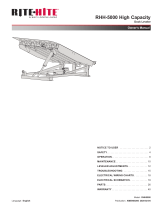
14. Stitch weld the rear frame angle (and rear spacers if
needed) to the rear curb angle. See figure 11. See
stenciled image at top of rear frame.
15. Weld front frame angle to the front curb angle. See
figure 9.
16. Clean and paint all weld and grind marks.
17. Remove front shipping pins from each Toe guard if
leveler is equipped with toe guards. Verify toe guards
move up and down freely.
18. Install Dock Bumpers. See Page 12.
19. Install Lip Supports. See Page 13.
20. Complete electrical installation. See Pages 14 - 18.
21. Lubricate leveler. See Figure 21 on Page 20.
22. Verify Lip Stop Bolt adjustment. See Figure 22 on
Page 21.
Pub. No. 1287 - March 2014 11
RITE-HITE®RHH50 Dock Leveler Installation Manual
INSTALLATION INSTRUCTIONS (Continued)
FIGURE 11 - REAR WELD LOCATION
Each Spacer
3/8” 3/8”
3/8”
5
Each End
Per Painted
Stencil
C
L
3/8” 3 MIN.
When No
Spacer
Exists
C
L

12 Pub. No. 1287 - March 2014
RITE-HITE®RHH50 Dock Leveler Installation Manual
INSTALLATION INSTRUCTIONS (Continued)
FIGURE - 13 LAMINATED BUMPER INSTALLATION
Min. 5/8” x 4”
Concrete Anchors
(Supplied By Others
Logo Decal
Dock Floor
Laminated Bumper
Leveler Lip
Side of Leveler Pit
1/4”
1/4”
1/4”
LAMINATED BUMPER INSTALLATION
(Standard)
1. Tack weld each bumper in position as shown in
Figure 13.
2. Each bumper should be secured with two 5/8 inch
concrete anchor bolts that are a minimum of 4 inch
long. (Ref. Rawl anchor 6942 - supplied by others.)
3. Using bumper mounting holes as a guide drill two 5/8
inch holes per bumper that are approximately 1/2
inch deeper than the bolt length that will be used.
4. Secure other end of each bumper with concrete
anchor bolts. Torque each bolt to 120 ft-lbs.
5. Weld the bumper side plate to the front vertical pit
angle.
6. Clean and paint all weld and grind marks.
7. Apply logo decal to front curb angle. See Figure 13.
DEEP PIT BASE PLATE ANCHORING
FIGURE - 12 DEEP PIT BASE PLATE ANCHOR INSTALLATION
Deep Pit Clevis Base Plate Anchoring:
1. Drill 6x anchor holes using base plate as a
guide.
2. Add shim under base plate.
3. Install 6x anchor bolts - 5/8” x 4” - RAWL 6942
(Supplied by others).
4. Torque anchor bolts to 60 ft. lbs.

Pub. No. 1287 - March 2014 13
RITE-HITE®RHH50 Dock Leveler Installation Manual
INSTALLATION INSTRUCTIONS (Continued)
LIP SUPPORT INSTALLATION
NOTE:
It is suggested to add two installation tabs just behind
the lip to support the leveler platform even and flush
with the dock floor before lip support installation. See
Figure 14.
1. Place marks 21-3/4” out from pit centerline on front
pit angle. See Figure 14.
2. On levelers with lips greater than 20” install lip keeper
mounting plate. See Figure 16.
3. Locate the centerline of the lip support assemblies.
4. Remove maintenance support and lower the leveler
until it is flush with dock level and lip is fully pendant.
5. Position lip support assemblies along the edge of the
lip and mark the bottom of lip support on front pit
angle.
6. Fully weld along the lip support and front pit angle.
See Figure 15.
7. Repeat the procedure for the second lip support
assembly.
8. Clean and paint all weld and grind marks.
FIGURE - 15 LIP SUPPORT FIGURE - 16 LIP MOUNTING PLATE
FIGURE - 14 INSTALLATION TABS
Installation Tabs
Lip Supports (2 ea.)
21-3/4”
C
L
Dock
21-3/4” Ref.
NOTE: Dimensions are Based On
Standard Pit Details
10”
1”
1 - 1/4”
8 -1/2”
5/8” Dia. x 4” LG. Min.
Concrete Anchors. (4 ea.)
(Supplied By Others)
FRONT VIEW
Dock Height
Lip
Length
+ 3/4”
1/4”
Front Frame Angle
Shim
(Supplied By Others)
Front Curb Angle
Pit
Floor
(2 ea.) 1/4” x 8-1/2” x 10” LG. M-1020
Lip Support Mounting Plate
(Supplied By Others)
SIDE VIEW
NOTE: Tack weld lip supports into place and check
to insure leveler platform is even and flush
with dock floor before final welding.
1/4”
Typ.
2 Places
Lip
Support
Front View
Top View
Side View

14 Pub. No. 1287 - March 2014
RITE-HITE®RHH50 Dock Leveler Installation Manual
INSTALLATION INSTRUCTIONS (Continued)
CONTROL BOX AND CONDUIT
INSTALLATION PROCEDURES.
1. Install the control box on a wall adjacent to the
overhead door at approximately 48" above the floor
level. See Figure 17.
2. Drill a hole for the power supply conduit (by others) in
the bottom of the control box. All holes drilled
through the control box must be through the
bottom of the box.
Control Box Installation Guidelines -
Temperature Controlled Applications.
a. Conduit should be routed to enter through the bottom
or side of the enclosure. A drip leg may be needed if
the conduit could fill with water.
b. Seal the conduit in any location where the conduit
transitions temperature zones that may produce
condensation.
c. Spacers should be installed between the enclosure
and the wall to provide tempature insulation and air
flow.
ELECTRICAL INSTALLATION
Connect wiring as indicated by the Wiring Diagrams and
Schematics see pages 14-15.
Incoming single phase power must connect into terminals
L1 and L2. Ground must attach to the ground lug
Incoming three phase power must connect into terminals
L1, L2, and L3. Ground must attach to the ground lug.
• The control box and all wiring should be
installed by a qualified electrician in
accordance with all national and local
electrical codes.
• If rigid conduit is installed, bonding must be
maintained between conduit connections by
using ground bushings and a jumper wire.
• When drilling holes in the box, DO NOT allow
the drill to go too deeply into the box.
Damage to the control systems may occur.
• DO NOT turn control box upside down to drill
any access holes. Cover internal electrical
components prior to drilling - this will prevent
debris from contacting the internal electrical
components.
• Remove all debris from box using a shop
vacuum. NEVER use air to blow debris from
the control box.
When working with electrical or electronic
controls, make sure that the power source has
been locked out and tagged according to OSHA
regulations and approved local electrical codes.
Minimum Wire Size Chart for Various Line Lengths and Line Loads
Line Length ( In Feet )
0-50 51-100 101-150 151-200 201-250 251-300 301-350 351-400
110-120/1 1HP 10 8644322
208-240/1 1HP 14 12 12 10 8886
208-240/3 1HP 14 14 12 12 10 10 10 8
380-415/3 1HP 14 14 14 14 14 14 14 14
440-480/3 1HP 14 14 14 14 14 14 14 14
575-600/3 1HP 14 14 14 14 14 14 14 14

Pub. No. 1287 - March 2014 15
RITE-HITE®RHH50 Dock Leveler Installation Manual
WIRING DIAGRAM
Customer
Load Center
1/2" Conduit
Minimum
Branch Circuit
Disconnect
To
Dock
#1
To
Dock
#2
To
Dock
#3
1/2" Conduit
Minimum
1" Conduit
Minimum
Control Box
48"
Hydraulic Power Unit
(Under Leveler)
Pit Junction Box
(Recommended Location)
Pit Junction Box
(Alternate Location)
Wire Harness
(3/4" Flexible Liquidtite Conduit)
TYPICAL ELECTRICAL INSTALLATION
Voltage / Phase / Hertz Leveler
Motor Full Load Amps
Branch Circuit Disconnect
Fusing Required
110 - 120 / 1 / 60
208 - 240 / 1 / 50/60
208 - 240 / 3 / 60
380 - 415 / 3 / 50/60
14.5 Amps
7.3 Amps
25 Amps
10 Amps
NOTE: Starting Inrush Amperage Typically Runs 2-3 Times Running Amperage.
NOTE: Variation Of Line Voltage Will Offset Motor Performance.
Restraint Connection
Goes Through Front
Frame Angle (If Applicable)
NOTE: Leveler and Restraint
Wires Can Be Ran
In The Same Conduit
Reference Only - See Control Box Drawing For Complete Fusing Requirements
440 - 480 / 3 / 60
575 - 600 / 3 / 60
4.4 - 3.8 Amps
2.4 Amps
2.2 Amps
1.7 Amps
6 Amps
4 Amps
4 Amps
4 Amps
FIGURE - 17 CONTROL BOX

16 Pub. No. 1287 - March 2014
RITE-HITE®RHH50 Dock Leveler Installation Manual
ELECTRICAL SCHEMATICS
NOTE: Typical Single Phase Electrical Schematic Shown. Please refer to Electrical Schematics inside the dock
leveler control box for specific voltage, phase, and options ordered on your dock leveler.
LS2
"DOOR INTERLOCK"
G
M
7. LS1 PROVIDED BY RITE-HITE WITH LEVELER FOR ARTD.
LS2 PROVIDED BY RITE-HITE OR OTHERS FOR OVERHEAD DOOR.
8. SEE OWNERS MANUAL FOR COMPLETE OPERATING INSTRUCTIONS.
9. FUSED DISCONNECT NOTES:
- FUSED DISCONNECT IS NOT PROVIDED BY RITE-HITE PRODUCTS
CORPORATION. FUSED DISCONNECT MUST BE PROVIDED BY OTHERS AND
INSTALLED PER LATEST EDITION OF UL508A AND NEC REQUIREMENTS.
- A BRANCH CIRCUIT DISCONNECT SHALL BE LOCATED WITHIN A 50 FT.
RADIUS AND BE VISIBLE FROM THE CONTROL BOX LOCATION.
[REFERENCE LATEST EDITION OF NEC, SECTION 430]
10. LEGEND:
DENOTES WIRE CONNECTIONS THRU TERMINAL BLOCK.
DENOTES MALE/FEMALE PLUG CONNECTION
DENOTES FIELD WIRES.
DENOTES WIRE NUT CONNECTION
1. REFER ALL INSTALLATION AND SERVICE TO QUALIFIED PERSONNEL.
2. INCOMING POWER FIELD WIRING - SEE MINIMUM WIRE SIZE CHART
3. POWER FROM DISCONNECT TO CONTROL BOX AND LEVELER MOTOR
FIELD WIRING TO BE MINIMUM #10GA. 60°/75°C COPPER WIRE,
INSULATED SUFFICIENTLY FOR INCOMING VOLTAGE.
4. ALL CONTROL FIELD WIRING TO BE MINIMUM #14GA. 60°/75°C
COPPER WIRE ONLY, INSULATED SUFFICIENTLY FOR INCOMING VOLTAGE.
5. ALL INTERNAL CONTROL BOX WIRING TO BE #16GA. MINIMUM, 90°C, RED
COPPER WIRE UNLESS OTHERWISE NOTED, INSULATED SUFFICEINTLY FOR
INCOMING VOLTAGE.
6. TORQUE REQUIREMENTS:
CONTACTOR: 8.9-22 LB-IN (MIN-MAX)
OVERLOAD RELAY: 16 LB-IN
GROUND TERMINAL: 35 LB-IN
TERMINAL BLOCK: 5.0-5.6 LB-IN (MIN-MAX)
1L1(BK)
N(WH)
N
1L1
H4(RD)
H7(RD)H3(RD)
PB2
H5(RD)
H3(RD) H4A(RD)
PB1
H5B(RD)
"LIP OUT"
H3(RD) H5(RD)
6
LS1
"ARTD LIMIT SWITCH"
H7
H4
X2/N
H12
5
N(WH) LIP OUT
CIRCUIT
H5A(RD)
H5 H5A
4
V
32
S1
L
1
H5B(RD)
ARTD
CIRCUIT
N(WH)
DUAL ELM TD
0.5A 250V
H2(RD) 1L1(BK) N(WH)
10FU1
H2A(RD)
H2(RD)
(14)
H3(RD)
(11)
CR1-1
PB3
"EMERGENCY STOP"
H2A(RD)
H2B(RD)
"RAISE"
(11) (14)
CR1-2
H2B(RD)
120VAC
120VAC
CR1-2
(A1)
(A1)
(A2)
(A2)
CR1-1
ESB INTERFACE RELAYS
CIRCUIT
N(WH)
E-STOP
N(WH)
LEVELER
CONTROLS
(A1)
1MCR
70VA
(96)
(95)
(A2)
1OL
N(WH)
JMPR
H3(RD) H3
109
108
107
106
105
104
102
103
101
100
111
110
119
122
121
120
118
117
116
115
112
114
113
SEE NOTE 4
SEE NOTE 3
T2
T1
LEVELER MOTOR-1 H.P.
(SEE MOTOR FLA CHART)
3450 RPM, 115v. 1 PH. 50/60 Hz.
(THERMALLY PROTECTED WITH
AUTOMATIC RESET)
WHTBLU
T1 T2
BLKYEL
SEE NOTE 3
SEE NOTE 9
FUSED DISCONNECT
(BY OTHERS)
G
N
DUMMY
N
#12GA. MIN.,
90°C
FROM CUSTOMER MAIN POWER & SAFETY PROTECTION DEVICE.
110-120v. 1PH. 60HZ. USE 25.0A DUAL ELEMENT TIME DELAY FUSES
L1
1FU1
1L1
1MCR 1OL
CONTACT BLOCK IS N.O. WHEN E-STOP
IS NOT REQUIRED
LIP OUT
SOLENOID 1
120 VAC, 0.3 AMPS
7 (BLK)
G
4(BLK)
X2 (WHT)
N.O.
12(WHT)
RT
(3)
(4)
GSHOWN WITH
DOOR CLOSED.
N.O.
TERMINAL BLOCK
JUMPER
TMR1:
SINGLE SHOT
~
(-) (+)
~
TO DOK-LOK CONTROL BOX FOR
RESTRAINT INTERCONNECT
BRNORG RED
(MAINTENANCE PENDANT TERMINAL)
FIGURE 18 - ELECTRICAL SCHEMATIC - 120V./60HZ. SINGLE PHASE

Pub. No. 1287 - March 2014 17
RITE-HITE®RHH50 Dock Leveler Installation Manual
ELECTRICAL SCHEMATICS (Continued)
LS2
"DOOR INTERLOCK"
CAUTION
G
M
7. LS1 PROVIDED BY RITE-HITE WITH LEVELER FOR ARTD.
LS2 PROVIDED BY RITE-HITE OR OTHERS FOR OVERHEAD DOOR.
8. SEE OWNERS MANUAL FOR COMPLETE OPERATING INSTRUCTIONS.
9. FUSED DISCONNECT NOTES:
- FUSED DISCONNECT IS NOT PROVIDED BY RITE-HITE PRODUCTS
CORPORATION. FUSED DISCONNECT MUST BE PROVIDED BY OTHERS AND
INSTALLED PER LATEST EDITION OF UL508A AND NEC REQUIREMENTS.
- A BRANCH CIRCUIT DISCONNECT SHALL BE LOCATED WITHIN A 50 FT.
RADIUS AND BE VISIBLE FROM THE CONTROL BOX LOCATION.
[REFERENCE LATEST EDITION OF NEC, SECTION 430]
10. LEGEND:
DENOTES WIRE CONNECTIONS THRU TERMINAL BLOCK.
DENOTES MALE/FEMALE PLUG CONNECTION
DENOTES FIELD WIRES.
DENOTES WIRE NUT CONNECTION
1. REFER ALL INSTALLATION AND SERVICE TO QUALIFIED PERSONNEL.
2. INCOMING POWER FIELD WIRING - SEE MINIMUM WIRE SIZE CHART
3. POWER FROM DISCONNECT TO CONTROL BOX AND LEVELER MOTOR
FIELD WIRING TO BE MINIMUM #14GA. 60°/75°C COPPER WIRE,
INSULATED SUFFICIENTLY FOR INCOMING VOLTAGE.
4. ALL CONTROL FIELD WIRING TO BE MINIMUM #14GA. 60°/75°C
COPPER WIRE ONLY, INSULATED SUFFICIENTLY FOR INCOMING VOLTAGE.
5. ALL INTERNAL CONTROL BOX WIRING TO BE #16GA. MINIMUM, 90°C, RED
COPPER WIRE UNLESS OTHERWISE NOTED, INSULATED SUFFICEINTLY FOR
INCOMING VOLTAGE.
6. TORQUE REQUIREMENTS:
CONTACTOR: 8.9-22 LB-IN (MIN-MAX)
OVERLOAD RELAY: 16 LB-IN
GROUND TERMINAL: 35 LB-IN
TERMINAL BLOCK: 5.0-5.6 LB-IN (MIN-MAX)
1L1(BK)
1L2(BK)
1L1
H4(RD)
H7(RD)H3(RD)
PB2
H5(RD)
H3(RD) H4A(RD)
PB1
H5B(RD)
"LIP OUT"
H3(RD) H5(RD)
6
LS1
"ARTD LIMIT SWITCH"
H7
H4
X2/N
H12
5
H5A(RD)
H5 H5A
4
V
32
S1
L
1
H5B(RD)
H2(RD)
H2A(RD)
H2(RD)
(14)
H3(RD)
(11)
PB3
"EMERGENCY STOP"
H2A(RD)
H2B(RD)
"RAISE"
(11) (14)
H2B(RD)
120VAC
120VAC
(A1)
(A1)
(A2)
(A2)
ESB INTERFACE RELAYS
(A1)
1MCR
70VA
(96)
(95)
(A2)
1OL
JMPR
1L2
LIP OUT
CIRCUIT
ARTD
CIRCUIT
X2(WH)
CIRCUIT
E-STOP
LEVELER
CONTROLS
X2(WH)
X2(WH)
X2(WH)
X2(WH)
X2(WH)
H3(RD) H3
CR1-1 CR1-2 CR1-2
CR1-1
109
108
107
106
105
104
102
103
101
100
111
110
119
122
121
120
118
117
116
115
112
114
113
SEE NOTE 3
T2
T1
LEVELER MOTOR-1 H.P.
(SEE MOTOR FLA CHART)
3450 RPM, 230v. 1 PH. 50/60 Hz.
(THERMALLY PROTECTED WITH
AUTOMATIC RESET)
BRNBLU
T1 T2
BLKYEL
SEE NOTE 3
#12GA. MIN.,
90°C
FROM CUSTOMER MAIN POWER & SAFETY PROTECTION DEVICE.
208-240v. 1PH. 50/60HZ. USE 10.0A DUAL ELEMENT TIME DELAY FUSES
1MCR 1OL
LIP OUT
SOLENOID 1
120 VAC, 0.3 AMPS
7 (BLK)
G
4(BLK)
X2 (WHT)
N.O.
12(WHT)
RT
(3)
(4)
GSHOWN WITH
DOOR CLOSED.
N.O.
TERMINAL BLOCK
JUMPER
TMR1:
SINGLE SHOT
~
(-) (+)
~
TO DOK-LOK CONTROL BOX FOR
RESTRAINT INTERCONNECT
REDORG WH
(BY OTHERS)
FUSED DISCONNECT
SEE NOTE 9
G
L2
1FU2
1L2
L1
1FU1
1L1
2FU1
2L1
2FU2 TRANSFORMER PRIMARY FUSING 1.0 AMP. 600v. CLASS CC
REJ DUAL ELM TD
2L2
TRANSFORMER FOR HYDRAULIC LEVELER CONTROLS ONLY!
DO NOT USE TO POWER AUXILIARY EQUIPMENT.
50VA
(H1)
230v.
(H3) (H2) (H4)
(X2)
#12GA. MINIMUM,
GREEN
(X1)
120v.
0.5 AMP. 250v.
DUAL ELM TIME DELAY
10FU1
CONTACT BLOCK IS N.O.
WHEN E-STOP IS NOT REQUIRED
(MAINTENANCE PENDANT TERMINAL)
FIGURE 19 - ELECTRICAL SCHEMATIC - 208-240V. 50/60HZ. SINGLE PHASE
NOTE: Typical Single Phase Electrical Schematic Shown. Please refer to Electrical Schematics inside the dock
leveler control box for specific voltage, phase, and options ordered on your dock leveler.

18 Pub. No. 1287 - March 2014
RITE-HITE®RHH50 Dock Leveler Installation Manual
ELECTRICAL SCHEMATICS (Continued)
LS2
"DOOR INTERLOCK"
CAUTION
M
G
45
78
6
9
12
T1 T2
3
T3
45
78
6
9
12
T1 T2
3
T3
45
78
6
9
12
T1 T2
3
T3
12
T1 T2
3
T3
7. LS1 PROVIDED BY RITE-HITE WITH LEVELER FOR ARTD.
LS2 PROVIDED BY RITE-HITE OR OTHERS FOR OVERHEAD DOOR.
8. SEE OWNERS MANUAL FOR COMPLETE OPERATING INSTRUCTIONS.
9. FUSED DISCONNECT NOTES:
- FUSED DISCONNECT IS NOT PROVIDED BY RITE-HITE PRODUCTS
CORPORATION. FUSED DISCONNECT MUST BE PROVIDED BY OTHERS AND
INSTALLED PER LATEST EDITION OF UL508A AND NEC REQUIREMENTS.
- A BRANCH CIRCUIT DISCONNECT SHALL BE LOCATED WITHIN A 50 FT.
RADIUS AND BE VISIBLE FROM THE CONTROL BOX LOCATION.
[REFERENCE LATEST EDITION OF NEC, SECTION 430]
10. LEGEND:
DENOTES WIRE CONNECTIONS THRU TERMINAL BLOCK.
DENOTES MALE/FEMALE PLUG CONNECTION
DENOTES FIELD WIRES.
DENOTES WIRE NUT CONNECTION
1. REFER ALL INSTALLATION AND SERVICE TO QUALIFIED PERSONNEL.
2. INCOMING POWER FIELD WIRING - SEE MINIMUM WIRE SIZE CHART
3. POWER FROM DISCONNECT TO CONTROL BOX AND LEVELER MOTOR
FIELD WIRING TO BE MINIMUM #14GA. 60°/75°C COPPER WIRE,
INSULATED SUFFICIENTLY FOR INCOMING VOLTAGE.
4. ALL CONTROL FIELD WIRING TO BE MINIMUM #14GA. 60°/75°C
COPPER WIRE ONLY, INSULATED SUFFICIENTLY FOR INCOMING VOLTAGE.
5. ALL INTERNAL CONTROL BOX WIRING TO BE #16GA. MINIMUM, 90°C, RED
COPPER WIRE UNLESS OTHERWISE NOTED, INSULATED SUFFICEINTLY FOR
INCOMING VOLTAGE.
6. TORQUE REQUIREMENTS:
CONTACTOR: 8.9-22 LB-IN (MIN-MAX)
OVERLOAD RELAY: 16 LB-IN
GROUND TERMINAL: 35 LB-IN
TERMINAL BLOCK: 5.0-5.6 LB-IN (MIN-MAX)
H4(RD)
H7(RD)H3(RD)
PB2
H5(RD)
H3(RD) H4A(RD)
PB1
H5B(RD)
"LIP OUT"
H3(RD) H5(RD)
6
LS1
"ARTD LIMIT SWITCH"
H7
H4
X2/N
H12
5
LIP OUT
CIRCUIT
H5A(RD)
H5 H5A
4
V
32
S1
L
1
H5B(RD)
ARTD
CIRCUIT
H2(RD) X2(WH)
H2A(RD)
H2(RD)
(14)
H3(RD)
(11)
PB3
"EMERGENCY STOP"
H2A(RD)
H2B(RD)
"RAISE"
(11) (14)
H2B(RD)
120VAC
120VAC
(A1)
(A1)
(A2)
(A2)
ESB INTERFACE RELAYS
CIRCUIT
E-STOP
LEVELER
CONTROLS
(A1)
1MCR
70VA
(96)
(95)
(A2)
1OL
JMPR
1L3
1L2
1L1
X2(WH)
X2(WH)
X2(WH)
X2(WH)
X2(WH)
H3(RD) H3
CR1-1 CR1-2 CR1-2
CR1-1
109
108
107
106
105
104
102
103
101
100
111
110
119
122
121
120
118
117
116
115
112
114
113
FROM CUSTOMER MAIN POWER & SAFETY PROTECTION DEVICE.
208-240v. 3PH. 60HZ. USE 6.0A DUAL ELEMENT TIME DELAY FUSES
380-415v. 3PH. 50/60HZ. USE 4.0A DUAL ELEMENT TIME DELAY FUSES
440-480v. 3PH. 60HZ. USE 4.0A DUAL ELEMENT TIME DELAY FUSES
575v. 3PH. 60HZ. USE 4.0A DUAL ELEMENT TIME DELAY FUSES
LIP OUT
SOLENOID 1
120 VAC, 0.3 AMPS
7 (BLK)
G
4(BLK)
X2 (WHT)
N.O.
12(WHT)
RT
(3)
(4)
GSHOWN WITH
DOOR CLOSED.
N.O.
TERMINAL BLOCK
JUMPER
TMR1:
SINGLE SHOT
~
(-) (+)
~
TO DOK-LOK CONTROL BOX FOR
RESTRAINT INTERCONNECT
2FU1
2L1
2FU2
TRANSFORMER PRIMARY FUSING:
CLASS CC REJ DUAL ELM TD
208-240v. USE 1.0 AMP. 600v.
380-480v. USE 0.5 AMP. 600v.
575v. USE 0.4 AMP. 600v.
2L2
TRANSFORMER FOR HYDRAULIC LEVELER CONTROLS ONLY!
DO NOT USE TO POWER AUXILIARY EQUIPMENT.
50VA
(H1) (H3) (H2) (H4)
(X2)
#12GA. MINIMUM,
GREEN
(X1)
120v.
0.5 AMP. 250v.
DUAL ELM TIME DELAY
10FU1
#16GA. MIN.,
90°C, BLACK,
COPPER WIRE
SEE NOTE 3
FUSED DISCONNECT
(BY OTHERS)
SEE NOTE 9
G
L3
L2
1FU3
1FU2
1L3
1L2
L1
1FU1
1L1
CONNECT T1, T2, T3
TO TERMINALS 1, 2, 3.
IF ROTATION IS WRONG,
REVERSE ANY 2 LINES.
T3
T2
ONE LEVELER PER OVERLOAD PROTECTION DEVICE.
[REFERENCE LATEST EDITION
OF NEC, SECTION 430]
1MCR 1OL
LEVELER MOTOR-1 H.P.
(SEE MOTOR FLA CHART)
@3450 R.P.M.
240v. 3 PH. 60 Hz.
SEE NOTE 3
T1
CONNECT T1, T2, T3
TO TERMINALS 1, 2, 3.
IF ROTATION IS WRONG,
REVERSE ANY 2 LINES.
LEVELER MOTOR-1 H.P.
(SEE MOTOR FLA CHART)
@3450 R.P.M.
380v. 3 PH. 50/60 Hz.
CONNECT T1, T2, T3
TO TERMINALS 1, 2, 3.
IF ROTATION IS WRONG,
REVERSE ANY 2 LINES.
LEVELER MOTOR-1 H.P.
(SEE MOTOR FLA CHART)
@3450 R.P.M.
480v. 3 PH. 60 Hz.
CONNECT T1, T2, T3
TO TERMINALS 1, 2, 3.
IF ROTATION IS WRONG,
REVERSE ANY 2 LINES.
LEVELER MOTOR-1 H.P.
(SEE MOTOR FLA CHART)
@3450 R.P.M.
575v. 3 PH. 60 Hz.
CONTACT BLOCK IS N.O. WHEN
E-STOP IS NOT REQUIRED
(MAINTENANCE PENDANT TERMINAL)
FIGURE 20 - ELECTRICAL SCHEMATIC - 3 PHASE
NOTE: Typical 3 Phase Electrical Schematic Shown. Please refer to Electrical Schematics inside the dock leveler
control box for specific voltage, phase, and options ordered on your dock leveler.

Pub. No. 1287 - March 2014 19
RITE-HITE®RHH50 Dock Leveler Installation Manual
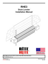
RETURN
.063
DIA
.109
DIA
SEQUENCE
VALVE
1000 PSI
P. O .
CHECK
M
SHUTTLE
VALVE
RELIEF VALVE
1200 PSI
N.O.
VALVE
(OPTION)
LIP CYLINDER
2.5" BORE X 6" STROKE
RAMP CYLINDER
4" BORE
VELOCITY
FUSE
7 GPM
MOTOR / PUMP
3.25 GPM
@ 900 PSI
RAMPLIP
FIGURE 21 - HYDRAULIC SCHEMATIC

20 Pub. No. 1287 - March 2014
RITE-HITE®RHH50 Dock Leveler Installation Manual
LEVELER LUBRICATION
FIGURE 22 - LEVELER LUBRICATION
Oil SAE 30 Weight
Dry Spray Lubricant
Grease
NOTE: Check Hydraulic Fluid Level.
NOTE: Inside and
under slots on
Safe-T-Lip.
NOTE: Apply grease
only if zerk fittings
are present.
/