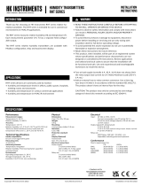
HK Instruments DPT-Priima-MOD User manual

Type
User manual

HK Instruments DPT-Priima-MOD is a multifunctional high-accuracy transmitter for measuring volume flow, velocity, and static and differential pressure. It is designed for cleanrooms and other demanding applications where precise measurements are crucial. The device offers automatic zero point calibration, eliminating the need for manual adjustments. With its Modbus communication capabilities, the DPT-Priima-MOD can be easily integrated into various systems, allowing for remote monitoring and configuration.

HK Instruments DPT-Priima-MOD is a multifunctional high-accuracy transmitter for measuring volume flow, velocity, and static and differential pressure. It is designed for cleanrooms and other demanding applications where precise measurements are crucial. The device offers automatic zero point calibration, eliminating the need for manual adjustments. With its Modbus communication capabilities, the DPT-Priima-MOD can be easily integrated into various systems, allowing for remote monitoring and configuration.

Copyright HK Instruments 2022 www.hkinstruments. Installaon version 1.0 2022
INSTALLATION
INSTRUCTIONS
DIFFERENTIAL PRESSURE TRANSMITTERS
DPT-Priima-MOD Series
READ THESE INSTRUCTIONS CAREFULLY BEFORE
ATTEMPTING TO INSTALL, OPERATE OR SERVICE THIS
DEVICE.
• Failuretoobservesafetyinformaonandcomplywith
instruconscanresultinPERSONALINJURY,DEATHAND/OR
PROPERTY DAMAGE.
• Toavoidelectricalshockordamagetoequipment,disconnect
powerbeforeinstallingorservicinganduseonlywiringwith
insulaonratedforfulldeviceoperangvoltage.
• Toavoidpotenalreand/orexplosiondonotuseinpotenally
ammableorexplosiveatmospheres.
• Retaintheseinstruconsforfuturereference.
• Thisproduct,wheninstalled,willbepartofanengineered
systemwhosespecicaonsandperformancecharacteriscs
arenotdesignedorcontrolledbyHKInstruments.Review
applicaonsandnaonalandlocalcodestoassurethatthe
installaonwillbefunconalandsafe.Useonlyexperiencedand
knowledgeabletechnicianstoinstallthisdevice.
Thank youforchoosinganHK Instruments DPT-Priima-MOD series
transmier.DPT-Priima-MODisamulfunconalhighaccuracytrans-
mierformeasuringvolumeow,velocity,andstacanddierenal
pressure.Itisdesignedforcleanroomsandotherdemandingapplica-
ons.Themeasurementscanbereadandtheconguraondonevia
Modbuscommunicaon.DPT-Priima-MODcanalsobeusedwithsev-
eraldierentmeasurementprobessuchasFloXact™orpitottube,and
airdampers.
DPT-Priima-MODmodelscomewithalocaldisplayandanautomac
zeropointcalibraon.Calibraoncercateavailableasanopon.
DPT-Priima-MODiscommonlyusedinapplicaonsrequiringhigh
measurementaccuracy:
•monitoringpressureincleanrooms
•monitoringpressuredierenceacrossthebuildingenvelope
•monitoringpressureandow
SPECIFICATIONS
Performance
Measurement ranges:
±120 Pa*, ±240 Pa, ±620 Pa, ±1240 Pa, ±2490 Pa
(selectableviamenuormodbus)
*defaultrange
Accuracy (at applied pressure):
0.4 % ±0.4 Pa
(Including:generalaccuracy,linearity,hysteresis,long
termstability,andrepeonerror)
Overpressure:
Proofpressure:10kPa
Burstpressure:30kPa
Zero point calibraon:
Automacautozero,manualpushbuonorviaModbus
register
Response me:
0.420s,selectableviamenuorviaModbusregister
(63%ofthechange)
Communicaon
Protocol:MODBUSoverSerialLine
TransmissionMode:RTU
Interface:RS485
Byteformat(11bits)inRTUmode:
 CodingSystem:8-bitbinary
 BitsperByte:
1 start bit
 8databits,leastsignicantbitsent
 rst
 1bitforparity
 1stopbit
Baudrate:selectableinconguraon
Modbusaddress:1−247addressesselectablein
conguraonmenu
Technical Specicaons
Media compability:
Dryairornon-aggressivegases
Pressure units (select via menu):
Pa,kPa,mbar,inWC,mmWC,psi
Flow units (select via menu):
Volume:m3/s,m3/h,cfm,l/s
Velocity:m/s,/min
Measuring element:
MEMS,noow-through
Environment:
Operangtemperature:-5...50°C
Temperaturecompensatedrange0...50°C
Storagetemperature:-40...70°C
Humidity:0to95%rH,noncondensing
Physical
Dimensions:
Case:102.0x71.5x36.0mm
Weight:
150g
Mounng:
2each4.3mmscrewholes,onesloed
Materials:
Case:ABS
Lid:PC
Pressurengs:Brass
Tubing:Silicone
Protecon standard:
IP54
Display
2-linedisplay(12characters/line)
 Line1:Volumeorvelocitymeasurement
 Line2:Pressuremeasurement
Size:46.0x14.5mm
Electrical connecons:
4-screwterminalblock
Wire:0.2–1.5mm2(16–24AWG)
Cable entry:
Strainrelief:M16
Knockout:16mm
Pressure ngs
Maleø5.2mm
+Highpressure
-Lowpressure
Electrical
Supply voltage:
24 VAC or VDC ± 10 %
Power consumpon:
<1W
<2.2WduringAZ-calibraon
Output signal:
viaModbus
Conformance
Meetsrequirementsfor:
CE:  UKCA:
EMC:  2014/30/EU S.I.2016/1091
RoHS:  2011/65/EU S.I.2012/3032
WEEE:  2012/19/EU S.I.2013/3113
APPLICATIONS
INTRODUCTION WARNING
RoHS
COMPLIANT
Copyright HK Instruments 2022 www.hkinstruments. Installaon version 1.0 2022
DPT
SCHEMATICS
DIMENSIONAL DRAWINGS
Figure 1a - Surface mounng
MOUNTING THE DEVICE CONTINUED
Figure 1b - Mounng orientaon
Figure 1c - Applicaon connecons
Connecon for display
Terminal block
Menu buons
ZERO
A
24 V
GND
SELECT
UP
DOWN
B
A
BPressure sensor
Led
DPT
4.3
Thepressuretubesareconnectedtoaowmeasurementprobe(i.e.FloXact),ortothe
measurementportsspeciedbythefanmanufacturer.PleaseseetheFloXactinstallaon
guideorthefanmanufacturer’stechnicalspecicaonsformoreinformaon.
YES NO NO
INSTALLATION
1)Mountthedeviceinthedesiredlocaon(seestep1).
2)Openthelidandroutethecablethroughthestrainreliefand
connectthewirestotheterminalblock(s)(seestep2).
3)Thedeviceisnowreadyforconguraon.
WARNING!Applypoweronlyaerthedeviceisproperlywired.
STEP 2: WIRING DIAGRAMS
ForCEcompliance,aproperlygroundedshieldingcableisrequired.
1)Unscrewthestrainreliefandroutethecable.
2)Connectthewiresasshowningure2.
3)Tightenthestrainrelief.
ItisrecommendedtouseshieldedtwistedpaircableforModbuscabling.
Thecableshieldmustbeearthedonlyinonepoint,normally,attheendof
themaincable.
Figure 2 - Wiring diagram
B
A
24 V
GND
+ Power supply
24 VDC / 24 VAC
Modbus
STEP 1: MOUNTING THE DEVICE
1)Selectthemounnglocaon(duct,wall,panel).
2)Usethedeviceasatemplateandmarkthescrewholes.
3)Mountwithappropriatescrews.
Pressure
Flow
Static pressure Filter/Damper
monitoring
Fan/Blower
monitoring
Not
connected
Copyright HK Instruments 2022 www.hkinstruments. Installaon version 1.0 2022
CONFIGURATION CONTINUED
STEP 3: CONFIGURATION
3)If
Commonprobe
selected:selectmeasurementunitsusedinthe
formula(akaFormulaunit)(i.e.l/s)
NOTE:Theowunit
none
isselectedbydefaultandthedisplay
showsonlythepressurereading.
1)AcvatethedeviceMenubypushingtheselectbuon
 for2seconds
2)Selectthefunconingmodeoftheowmeter:
-Select
Manufacturer
whenconnecngDPT-Priima-MODtoa
fanwithpressuremeasurementpoints
-Select
Commonprobe
whenusingDPT-Priima-MODwitha
commonmeasurementprobethatfollowstheformula:
 q=k∙√P
(i.e.FloXact)
MANUFACTURER
Common probe
SELECT
UP
DOWN
Common probe Flakt Woods
SELECT
UP
DOWN
FORMULA UNIT
l/s
SELECT
UP
DOWN
4)SelectK-value
a.Ifmanufacturerselectedinstep2:
EachfanhasaspecicK-value.SelecttheK-valuefromfanmanufac-
turer’sspecicaons.
Manufacturer: K-value:
Fläktwoods k=0.3...99
Rosenberg k=37...800
Nicotra-Gebhardt k=50...4700
Comefri  k=10...2000
Ziehl  k=10...1500
ebm-papst k=10...1500
Gebhardt k=50...4700
Nicotra  k=50...5300
8)Responseme:Selectresponsemebetween0.420s.
RESPONSE TIME
20 s
SELECT
UP
DOWN
12)Pushselectbuontosavechangesandtoexitmenu.
SELECT
EXIT MENU
SELECT
b. If
Commonprobe
selectedinstep1:
Each common probe has a specic K-value. Select the K-value from
commonprobemanufacturer’sspecicaons.
AvailableK-valuerange:0.001...9999.000.
K-VALUE
9000.000
SELECT
UP
DOWN
9)SelecttheaddressforModbus:1...247.
10)Selectthebaudrate:9600/19200/38400.
ADDRESS
99
SELECT
UP
DOWN
BAUD RATE
9600
SELECT
UP
DOWN
11)Selecttheparitybit:None/Even/Odd.
PARITY BIT
NONE
SELECT
UP
DOWN
STEP 4: ZEROING THE DEVICE
NOTE! Always zero the device before use.
Tozerothedevicethreeoponsareavailable:
1)Autozerocalibraon(manualzeroingnotrequired)
2)ManualPushbuonzeropointcalibraon
3)ViaModbusregister
1)Autozerocalibraon
Autozerocalibraon(-AZ)isanautozerofunconintheformofan
automaczeroingcircuitbuiltintothePCBboard.Theautozerocali-
braonelectronicallyadjuststhetransmierzeroatpredetermined
meinter vals(every10minutes).Thefunconeliminatesalloutput
signaldriduetothermal,electronicormechanicaleects,aswellas
theneedfortechnicianstoremovehighandlowpressuretubeswhen
performinginialorperiodictransmierzeropointcalibraon.The
autozeroadjustmenttakes4secondsaerwhichthedevicereturnsto
itsnormalmeasuringmode.Duringthe4secondadjustmentperiod,
theoutputanddisplayvalueswillfreezetothelatestmeasuredvalue.
Transmiersequippedwiththeautozerocalibraonarevirtuallymain-
tenancefreeandmanualzeroingisnotrequired.
5)Selectpressureunitfordisplay:Pa,kPa,mbar,inWC,mmWC,psior
none.
PRESS.UNIT
Pa
SELECT
UP
DOWN
7)Selectowunitfordisplay:
Flowvolume:m3/s,m3/h,cfm,l/s,none(default)
Velocity:m/s,f/min,none
FLOW UNIT
m3/s
SELECT
UP
DOWN
6)Selectdesiredpressurerange:
±120 Pa, ±240 Pa, ±620 Pa, ±1240 Pa, ±2490 Pa
PRESS. RANGE
±120 Pa
SELECT
UP
DOWN
Copyright HK Instruments 2022 www.hkinstruments. Installaon version 1.0 2022
Thesellerisobligatedtoprovideawarrantyofveyearsforthedeliv-
eredgoodsregardingmaterialandmanufacturing.Thewarrantyperiod
isconsideredtostartonthedeliverydateoftheproduct.Ifadefect
inrawmaterialsoraproduconawisfound,thesellerisobligated,
whentheproductissenttothesellerwithoutdelayorbeforeexpira-
onofthewarranty,toamendthemistakeathis/herdiscreoneither
byrepairing the defecve product or by delivering free ofcharge to
thebuyeranewawlessproductandsendingittothebuyer.Delivery
costsfortherepairunderwarrantywillbepaidbythebuyerandthe
return costs by the seller. The warranty does not comprise damages
causedbyaccident,lightning,oodorothernaturalphenomenon,nor-
malwearandtear,improperorcarelesshandling,abnormaluse,over-
loading,improperstorage,incorrectcareorreconstrucon,orchanges
andinstallaonworknotdonebytheseller.Theseleconofmateri-
alsfordevicespronetocorrosionisthebuyer’sresponsibility,unless
otherwise is legally agreed upon. Should the manufacturer alter the
structureofthedevice,thesellerisnotobligatedtomakecomparable
changestodevicesalreadypurchased.Appealingforwarrantyrequires
thatthebuyerhascorrectlyfullledhis/herduesarisenfromthede-
liveryandstatedinthecontract.Thesellerwillgiveanewwarrantyfor
goodsthathavebeenreplacedorrepairedwithinthewarranty,how-
everonlytotheexpiraonoftheoriginalproduct’swarrantyme.The
warrantyincludestherepairofadefecvepartordevice,orifneeded,
anewpartordevice,butnotinstallaonorexchangecosts.Underno
circumstanceisthesellerliablefordamagescompensaonforindirect
damage.
2)ManualPushbuonzeropointcalibraon
NOTE:Supplyvoltagemustbeconnectedatleastonehourpriorto
zeropointadjustment.
a)Disconnectbothpressuretubesfromthepressureportslabeled+
and–.
b)PushdownthezerobuonunltheLEDlight(red)turnsonand
thedisplayreads“zeroing”(displayopononly).(seegure3)
c)Thezeroingofthedevicewillproceedautomacallyin4seconds.
ZeroingiscompletewhentheLEDturnso,andthedisplayreads
0(displayopononly).
d)ReinstallthepressuretubesensuringthattheHighpressuretube
isconnectedtotheportlabeled+,andtheLowpressuretubeis
connectedtotheportlabeled−.
3)ViaModbusregister
Makesurethereisnopressureintheductwhenthezeroingisdone
viaModbusregister.
a) Disconnect both pressure tubes from the pressure ports labeled +
and –.
b) Push down the zero buon (joysck) unl the LED light (red)
turns on and the display reads “zeroing” (display opon only). (see
Figure 6)
c) The zeroing of the device will proceed automacally. Zeroing is
complete when the LED turns off, and the display reads 0 (display
opon only).
d) Reinstall the pressure tubes, ensuring the High pressure tube is
connected to the port labeled +, and the Low pressure tube is
connected to the port labeled −.
Press down buon
LED turns ON
Display reads “Zeroing”
LED
Figure 3
ZEROING THE DEVICE CONTINUED
STEP 5: MODBUS REGISTERS
Register Parameter descripon Data Type Value Range
3x0001 Programversion 16 bit 0...9900 0,00...99,00
3x0002 PressurereadingPa 16 bit -24900...24900* ± 2490.0 Pa
3x0003 PressurereadingkPa 16 bit -24900...24900* ±2.4900kPa
3x0004 Pressurereadingmbar 16 bit -24900...24900* ± 24.900 Pa
3x0005 PressurereadingmmWC 16 bit -25400...25400* ±253.91mmWC
3x0006 PressurereadinginWC 16 bit -10000...10000* ±10.000inWC
3x0007 Pressurereadingpsi 16 bit -3610...3610* ±0.3611psi
3x0008 Flowm3/s 16 bit 0...10000 0...100m3/s
3x0009 Flowm3/h 16 bit 0...30000 0...30000m3/h
3x0010 Flowcfm 16 bit 0...30000 0...30000cfm
3x0011 Flowl/s 16 bit 0...3000 0...3000l/s
3x0012 Velocitym/s 16 bit 0...1000 0...100m/s
3x0013 Velocityf/min 16 bit 0...5000 0...5000f/min
Funconcode04-Readinputregister
MODBUS REGISTERS CONTINUED
Funconcode05-Writesinglecoil
Register Parameter descripon Data Type Value Range
0x0001 Zeropointcalibraon Bit 0 0...1 On-O
WARRANTY POLICY
RECYCLING/DISPOSAL
The parts le over from installaon should be
recycled according to your local instrucons.
Decommissioned devices should be taken to a
recyclingsitethatspecializesinelectronicwaste.
*)Thevalueandrangearedeterminedbytheselectedpressurerange±120Pa,±240Pa,±620Pa,
±1240Pa,±2490Pa.Thevaluesshowninthetablewhenthelargestareaisselected.
Funcon code 03 - Read input holding register, Funcon code 06 -
Writesingleregister,Funconcode16-Writemulpleregisters
Register Parameter descripon Data Type Value Range
4x0001 Manufacturer 16 bit 0...8
0=FläktWoods,1=Rosenberg,
2=Nicotra-Gebhardt,3=Comefri,
4=Ziehl,5=ebm-papst,6=Gebhardt,
7=Nicotra,8=Commonprobe
4x0002 Formulaunit(ifmanufacturer
selecon=commonprobe) 16 bit 0...5 0:m3/s,1:m3/h,2:cfm,3:l/s,
4:m/s,5:f/min
4x0003 K-factorinteger 16 bit 0...9999 0...9999
4x0004 K-factordecimal 16 bit 0...999 0...999
4x0005 Responseme 16 bit 0...20 0=0.4s,1=1s,2=2s...20=20s
4x0006 PressureRange 16 bit 0...4 0=±120Pa,1=±240Pa,2=±620Pa,
3=±1240Pa,4=±2490Pa
  • Page 1 1
  • Page 2 2
  • Page 3 3
  • Page 4 4

HK Instruments DPT-Priima-MOD User manual

Type
User manual

HK Instruments DPT-Priima-MOD is a multifunctional high-accuracy transmitter for measuring volume flow, velocity, and static and differential pressure. It is designed for cleanrooms and other demanding applications where precise measurements are crucial. The device offers automatic zero point calibration, eliminating the need for manual adjustments. With its Modbus communication capabilities, the DPT-Priima-MOD can be easily integrated into various systems, allowing for remote monitoring and configuration.

Ask a question and I''ll find the answer in the document

Finding information in a document is now easier with AI