Page is loading ...

Copyright HK Instruments 2019 www.hkinstruments. Installaon version 8.0 2019
INSTALLATION
INSTRUCTIONS
DIFFERENTIAL PRESSURE TRANSMITTERS
DPT-Dual-MOD Series
• READ THESE INSTRUCTIONS CAREFULLY BEFORE
ATTEMPTING TO INSTALL, OPERATE OR SERVICE THIS
DEVICE.
• Failuretoobservesafetyinformaonandcomplywith
instruconscanresultinPERSONALINJURY,DEATHAND/OR
PROPERTY DAMAGE.
• Toavoidelectricalshockordamagetoequipment,disconnect
powerbeforeinstallingorservicinganduseonlywiringwith
insulaonratedforfulldeviceoperangvoltage.
• Toavoidpotenalreand/orexplosiondonotuseinpotenally
ammableorexplosiveatmospheres.
• Retaintheseinstruconsforfuturereference.
• Thisproduct,wheninstalled,willbepartofanengineered
systemwhosespecicaonsandperformancecharacteriscs
arenotdesignedorcontrolledbyHKInstruments.Review
applicaonsandnaonalandlocalcodestoassurethatthe
installaonwillbefunconalandsafe.Useonlyexperiencedand
knowledgeabletechnicianstoinstallthisdevice.
SPECIFICATIONS
ThankyouforchoosinganHKInstrumentsDPT-Dual-MODseries
dierenalpressuretransmier.DPT-Dual-MODcombinestwodif-
ferenalpressuretransmiersintoonedevice.Itoersapossibility
tomeasurepressurefromtwodierentpoints.IthasaModbusin-
terfaceandanInputterminal.
TheInputterminalenablesreadingofmulpleothersignalssuchas
temperatureorcontrolrelaysoverModbus.TheInputterminalhas
two input channels designed to accept 0−10 V, NTC10k, Pt1000,
Ni1000/(-LG),andBININ(potenalfreecontact)signals.Forexam-
ple,DPT-Dual-MODcanreadvaluesfromtwodierenalpressure
measurementpointsandtwotemperaturemeasurementpoints.
DPT-Dual-MODseriesdevicesarecommonlyusedinHVAC/R
systems for:
•fan,blowerandltermonitoring
•pressureandowmonitoring
•valveanddampercontrol
•pressuremonitoringincleanrooms
DPT-Dual-MOD-AHUcanalsobeusedfor:
•airowmonitoringacrosscentrifugalfansandblowers
•in-ductairowmonitoring
•VAVapplicaons
SPECIFICATIONS
Performance
Accuracy (from applied pressure):
Model2500:
Pressure<125Pa=1%+±2Pa
Pressure>125Pa=1%+±1Pa
Model7000:
Pressure<125Pa=1.5%+±2Pa
Pressure>125Pa=1.5%+±1Pa
(Including:generalaccuracy,linearity,hysteresis,long
termstabilityandrepeonerror)
Input accuracy:
<0,5%
Response me:
1...20sselectableviamenu
Overpressure:
Proofpressure:25kPa
Burstpressure:30kPa
Communicaon
Protocol:MODBUSoverSerialLine
TransmissionMode:RTU
Interface:RS485
Byteformat(11bits)inRTUmode:
CodingSystem:8-bitbinary
BitsperByte:
1startbit
8databits,leastsignicantbitsent
rst
1bitforparity
1stopbit
Baudrate:selectableinconguraon
Modbusaddress:1−247addressesselectablein
conguraonmenu
Zeropointcalibraonopons:
•Manualpushbuonautozero
•ViaModbuswritecoil
Technical Specicaons
Media compability:
Dryairornon-aggressivegases
Measuring units on display (Selectable via menu):
Pressure:Pa,kPa,mbar,inchWC,mmWC,psi
Flow(AHUmodel):m3/s,m3/hr,cfm,l/s,m/s,/min
Measuring element:
MEMS,noow-through
Environment:
Operangtemperature:-20...+50°C
Temperaturecompensatedrange0...+50°C
Storagetemperature:-40...+70°C
Humidity:0to95%rH
Physical
Dimensions:
Case:102.0x71.5x36.0mm
Weight:
150g,withaccessories290g
Mounng:
2each4.3mmscrewholes,onesloed
Materials:
Case: ABS
Lid:PC
Pressure inlets: Brass
Ductconnectors:ABS
Tubing:PVC
Protecon standard:
IP54
Display:
2-linedisplay(12characters/line)
Line1:acvemeasurement,inletA
Line2:acvemeasurement,inletB
Ifinputsareselected,thelinesshowalsoinput
informaon(forexampletemperature)
Electrical Connecons:
4+4springloadterminals,max1.5mm2
CableEntry:M20
Pressure connecons:
Male 5,0mmand6,3mm
Electrical
Supply voltage:
24VACorVDC±10%
Power consumpon:
<1.3W
Output signal:
viaModbus
Input signals:
2xinput(0...10v,NTC10k,Pt1000,NI1000/(-LG),or
BININ)
Conformance
MeetsrequirementsforCEmarking:
EMCdirecve2014/30/EU
RoHSDirecve2011/65/EU
WEEEDirecve2012/19/EU
INTRODUCTION WARNING
APPLICATIONS
COMPANY WITH
MANAGEMENT SYSTEM
CERTIFIED BY DNV GL
= ISO 9001 = ISO 14001 =
RoHS 2
2011/65/EU

Copyright HK Instruments 2019 www.hkinstruments. Installaon version 8.0 2019
SCHEMATICS
DIMENSIONAL DRAWINGS
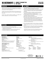
Figure 1a - Mounng orientaon
Figure 1b - Applicaon connecons
Display connecon
A
B
24 V
GND
LEDs
Joysck 1
Joysck 2
Joysck 3
Select
Up
Down
Menu buons
Terminal
blocks
Pressure
sensors
Input terminal
configuraon
jumpers
Input 1
Input 2
GND
GND
InputOutput
Pressure
inlet A Pressure
inlet B
YES NO NO
Stac pressure Filter/Damper
monitoring
Fan/Blower
monitoring
Not
connected
INSTALLATION
1)Mountthedeviceinthedesiredlocaon(seestep1).
2)Openthelidandroutethecablethroughthestrainreliefand
connectthewirestotheterminalblock(s)(seestep2).
3)Thedeviceisnowreadyforconguraon.
WARNING!Applypoweronlyaerthedeviceisproperlywired.
Pressure
Flow
Thepressuretubesareconnectedtoaowmeasurementprobe(i.e.FloXact),ortothe
measurementportsspeciedbythefanmanufacturer.PleaseseetheFloXactinstallaon
guideorthefanmanufacturer’stechnicalspecicaonsformoreinformaon.
STEP 1: MOUNTING THE DEVICE
1)Selectthemounnglocaon(duct,wall,panel).
2)Usethedeviceasatemplateandmarkthescrewholes.
3)Mountwithappropriatescrews.
MOUNTING THE DEVICE CONTINUED
STEP 2: WIRING DIAGRAMS
ForCEcompliance,aproperlygroundedshieldingcableisrequired.
1)Unscrewthestrainreliefandroutethecable(s).
2)Connectthewiresasshowningure2aand2b.
3)Tightenthestrainrelief.
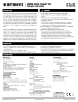
Figure 2a - Wiring diagram
Figure 2b - Wiring diagram example for input signals
Input 1
Input 2
GND
GND
Pt1000
NTC10k
J1
J2
J3
IN1 IN2
Input 1 Pt1000 temperature:
Funcon 04 - Read input register 3x0005
Input 2 NTC10k temperature:
Funcon 04 - Read input register 3x0008
A
B
24 V
GND
+ Power Supply
24VDC / 24VAC
Input 1
Input 2
GND
GND
Modbus

Copyright HK Instruments 2019 www.hkinstruments. Installaon version 8.0 2019
NOTE! Always zero the device before use.
Supplyvoltagemustbeconnectedonehourbeforethezeropoint
adjustmentiscarriedout.AccessviaModbusorbypushbuon.
1)Loosebothtubesfromthepressureinlets+and-.
2)Regularmodel:Presstheselectbuonbriey.
AHUmodel:Presstheselectbuonfor3secto
enterthemenuandselectzero sensors.
3)WaitunltheLEDturnsoandtheninstalltubesagainforthe
pressureinlets.
CONFIGURATION CONTINUED
STEP 3: CONFIGURATION
9)SelecttheaddressforModbus:1...247.
BAUD RATE
9600
SELECT
UP
DOWN
ADDRESS
99
SELECT
UP
DOWN
PARITY BIT
NONE
SELECT
UP
DOWN
10)Selectthebaudrate:9600/19200/38400.
11)Selecttheparitybit:None/Even/Odd.
12)Selectthepressureunitfordisplay:Pa/inchWC/mmWC/psi/mbar.
(Not for AHU model)
PRESS. UNIT
Pa
SELECT
UP
DOWN
13)Selecttheresponseme:1...20s.
RESPONSETIME
20 s
SELECT
UP
DOWN
14)Pushtheselectbuontoexitmenu.
SELECT
EXIT MENU SELECT
STEP 4: ZERO POINT ADJUSTMENT
SELECT
1)AcvatethedeviceMenubypushingthetheselectbuonfor2
seconds.
Points 2–8 for AHU model only:
3)If
commonprobe
selected:selectmeasurementunitsusedinthe
formula(akaFormulaunit)(i.e.l/s)
FORMULA UNIT
l/s
SELECT
UP
DOWN
4)SelectK-value
Each applicaon has a specic K-value. Select the K-value from the
manufacturer’sspecicaons.
AvailableK-valuerange:0.001...9999.000
K-VALUE
9000.000
SELECT
UP
DOWN
5)Selectpressureunitfordisplay:Pa,kPa,mbar,inWCormmWC
PRESS.UNIT
Pa
SELECT
UP
DOWN
6)Selectowunitfordisplay:
Flowvolume:m3/s,m3/h,cfm,l/s
Velocity:m/s,f/min
FLOW UNIT
m3/s
SELECT
UP
DOWN
2)Selectthefunconingmodeofthedevice:
-SelectManufacturerwhenconnecngDPT-Dual-MOD-AHUtoa
fanwithpressuremeasurementpoints
-SelectCommon probe whenusingDPT-Dual-MOD-AHUwitha
commonmeasurementprobethatfollowstheformula:
q=k∙√∆P(i.e.FloXact)
7)Selectthethetypeofsensorforinput1:
NTC10k, Ni1000-LG, Ni1000, Pt1000, VINPUT (voltage 0–10 V),
none(sensor1willnotbeshownondisplay)
SENSOR 1
NTC10K
SELECT
UP
DOWN
7)Selectthethetypeofsensorforinput2:
NTC10k, Ni1000-LG, Ni1000, Pt1000, VINPUT (voltage 0–10 V),
none(sensor2willnotbeshownondisplay)
SENSOR 2
NONE
SELECT
UP
DOWN
MANUFACTURER
Common probe
SELECT
UP
DOWN
Common probe Flakt Woods
SELECT
UP
DOWN

Copyright HK Instruments 2019 www.hkinstruments. Installaon version 8.0 2019
Thesellerisobligatedtoprovideawarrantyofveyearsforthedeliv-
eredgoodsregardingmaterialandmanufacturing.Thewarrantyperiod
isconsideredtostartonthedeliverydateoftheproduct.Ifadefectin
rawmaterialsoraproduconawisfound,thesellerisobligated,when
theproductissenttothesellerwithoutdelayorbeforeexpiraonof
thewarranty,toamendthemistakeathis/herdiscreoneitherbyre-
pairingthedefecveproductorbydeliveringfreeofchargetothebuy-
eranewawlessproductandsendingittothebuyer.Deliverycosts
fortherepairunderwarrantywillbepaidbythebuyerandthereturn
costsbytheseller.Thewarrantydoesnotcomprisedamagescausedby
accident, lightning, ood orothernaturalphenomenon, normal wear
andtear,improperorcarelesshandling,abnormaluse,overloading,im-
properstorage,incorrectcareorreconstrucon,orchangesandinstal-
laonworknotdonebythesellerorhis/herauthorizedrepresentave.
Theseleconofmaterialsfordevicespronetocorrosionisthebuyer’s
responsibility,unlessotherwiseislegallyagreedupon.Shouldtheman-
ufactureralterthestructureofthedevice,thesellerisnotobligatedto
makecomparablechangestodevicesalreadypurchased.Appealingfor
warrantyrequiresthatthebuyerhascorrectlyfullledhis/herdues
arisenfromthedeliveryandstatedinthecontract.Thesellerwillgive
anewwarrantyforgoodsthathavebeenreplacedorrepairedwithin
thewarranty,howeveronlytotheexpiraonoftheoriginalproduct’s
warrantyme.Thewarrantyincludestherepairofadefecvepartor
device,orifneeded,anewpartordevice,butnotinstallaonorex-
changecosts. Underno circumstanceistheseller liablefor damages
compensaonforindirectdamage.
Register Parameter descripon Data Type Value Range
3x0001 Programversion 16bit 0...1000 0,00...99,00
3x0002 PressurereadingA 16bit -250...2500/7000 -250...2500/7000(Pa)
3x0003 PressurereadingB 16bit -250...2500/7000 -250...2500/7000(Pa)
3x0004 Input1:0...10V 16bit 0...1000 0...100%
3x0005 Input1:Pt1000 16bit -500...500 -50...+50°C
3x0006 Input1:Ni1000 16bit -500...500 -50...+50°C
3x0007 Input1:Ni1000-LG 16bit -500...500 -50...+50°C
3x0008 Input1:NTC10k 16bit -500...500 -50...+50°C
3x0009 Input2:0...10V 16bit 0...1000 0...100%
3x0010 Input2:Pt1000 16bit -500...500 -50...+50°C
3x0011 Input2:Ni1000 16bit -500...500 -50...+50°C
3x0012 Input2:Ni1000-LG 16bit -500...500 -50...+50°C
3x0013 Input2:NTC10k 16bit -500...500 -50...+50°C
AHU model only:
3x0014 Flowm3/s 16bit 0...10000 0...100m3/s
3x0015 Flowm3/h 16bit 0...30000 0...30000m3/h
3x0016 Flowcfm 16bit 0...30000 0...30000cfm
3x0017 Flowl/s 16bit 0...3000 0...3000l/s
3x0018 Velocitym/s 16bit 0...1000 0...100m/s
3x0019 Velocityf/min 16bit 0...5000 0...5000f/min
Funconcode04-Readinputregister
The parts le over from installaon should be
recycled according to your local instrucons.
Decommissioned devices should be taken to a
recyclingsitethatspecializesinelectronicwaste.
STEP 6: MODBUS REGISTERS
RECYCLING/DISPOSAL
WARRANTY POLICY
Funconcode03-Readinputholdingregister-AHU model only
Register Parameter descripon Data Type Value Range
4x0001 Manufacturer 16bit 0...7 0...7
4x0002
Formulaunit(Manufac-
turer=7)
16bit 0...5
0=m3/s,1=f/min,2=m/s,3=l/s,4=cfm,
5=m3/h
4x0003 K-FactorInteger 16bit 0...9999 0...9999
4x0004 K-FactorDecimal 16bit 0...999 0...999
4x0005 ResponseTime 16bit 0...20 0...20s
MODBUS REGISTERS CONTINUED
Funconcode02-Readinputstatus
Register Parameter descripon Data Type Value Range
1x0001 Input1:BININ Bit0 0...1 On-O
1x0002 Input2:BININ Bit0 0...1 On-O
Funcon05-Writesinglecoil
Register Parameter descripon Data Type Value Range
0x0001 Zeroingfuncon Bit0 0...1 On-O
Funconcode06-Writesingleregister-AHU model only
Register Parameter descripon Data Type Value Range
4x0001 Manufacturer 16bit 0...7 0...7
4x0002
Formulaunit(Manufac-
turer=7)
16bit 0...5
0=m3/s,1=f/min,2=m/s,3=l/s,4=cfm,
5=m3/h
4x0003 K-FactorInteger 16bit 0...9999 0...9999
4x0004 K-FactorDecimal 16bit 0...999 0...999
4x0005 ResponseTime 16bit 0...20 0...20s
STEP 5: INPUT SIGNAL CONFIGURATION
InputsignalscanbereadoverModbusviaDPT-MODRS485interface.
Signals Accuracy for measurement Resoluon
0...10V <0,5% 0,1%
NTC10k <0,5% 0,1%
Pt1000 <0,5% 0,1%
Ni1000/(-LG) <0,5% 0,1%
BININ(potenalfreecontact)
Thejumpersshouldbesetaccordingtotheinstruconsbelowandthe
valueshouldbereadfromtherightregister.Bothinputscanbecong-
uredindependently.
Figure 3 - Input signal conguraon
J1
J2
J3
IN1 IN2
J1
J1
J1
J2
J2
J2
J3
J3
J3
NTC10k / BIN IN
Pt1000 / Ni10007(-LG)
0...10 V
/