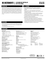
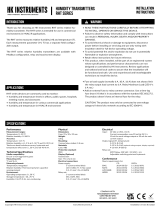
HK Instruments 40C AIR FLOW AND VELOCITY TRANSMITTERS DPT-Flow Series Installation guide

Type
Installation guide

HK Instruments 40C AIR FLOW AND VELOCITY TRANSMITTERS DPT-Flow Series are designed to measure air flow, velocity, and differential pressure. They are commonly used in HVAC/R systems for air flow monitoring across centrifugal fans and blowers, in-duct air flow monitoring, and VAV applications. The DPT-Flow Series features an easy-to-read display, manual pushbutton zero point calibration, and optional autozero calibration. With its high accuracy and wide measurement range, the DPT-Flow Series is a reliable choice for a variety of air flow monitoring applications.

HK Instruments 40C AIR FLOW AND VELOCITY TRANSMITTERS DPT-Flow Series are designed to measure air flow, velocity, and differential pressure. They are commonly used in HVAC/R systems for air flow monitoring across centrifugal fans and blowers, in-duct air flow monitoring, and VAV applications. The DPT-Flow Series features an easy-to-read display, manual pushbutton zero point calibration, and optional autozero calibration. With its high accuracy and wide measurement range, the DPT-Flow Series is a reliable choice for a variety of air flow monitoring applications.

Copyright HK Instruments 2022 www.hkinstruments. Installaon version 9.0 2022
INSTALLATION
INSTRUCTIONS
AIR FLOW AND VELOCITY TRANSMITTERS
DPT-Flow Series
READ THESE INSTRUCTIONS CAREFULLY BEFORE
ATTEMPTING TO INSTALL, OPERATE OR SERVICE THIS
DEVICE.
• Failuretoobservesafetyinformaonandcomplywith
instruconscanresultinPERSONALINJURY,DEATHAND/OR
PROPERTY DAMAGE.
• Toavoidelectricalshockordamagetoequipment,disconnect
powerbeforeinstallingorservicinganduseonlywiringwith
insulaonratedforfulldeviceoperangvoltage.
• Toavoidpotenalreand/orexplosiondonotuseinpotenally
ammableorexplosiveatmospheres.
• Retaintheseinstruconsforfuturereference.
• Thisproduct,wheninstalled,willbepartofanengineered
systemwhosespecicaonsandperformancecharacteriscs
arenotdesignedorcontrolledbyHKInstruments.Review
applicaonsandnaonalandlocalcodestoassurethatthe
installaonwillbefunconalandsafe.Useonlyexperiencedand
knowledgeabletechnicianstoinstallthisdevice.
ThankyouforchoosinganHKInstrumentsDPT-Flowseriesairow
transmier.TheDPT-Flowseriesisintendedforuseincommercial
environments.TheDPT-Flowmeasuresairow,velocityanddier-
enalpressure.Itisdesignedtobeusedincombinaonwithairow
measuring probes (i.e. FloXact), dampers or with centrifugal fans
thatprovidedierenalpressureconneconsandK-values.
TheDPT-FlowseriesofairowtransmiersiscomprisedofDPT-
Flow-1000, DPT-Flow-2000, DPT-Flow-5000 and DPT-Flow-7000
withmeasurementrangesof0–1000Pa,0–2000Pa,0–5000Paand
0–7000Parespecvely.Allmodelscomewithdisplayandmanual
pushbuon zeropoint calibraon. Oponal autozero calibraonis
also available.
DPT-FlowseriesdevicesarecommonlyusedinHVAC/Rsystemsfor:
•airowmonitoringacrosscentrifugalfansandblowers
•in-ductairowmonitoring
•VAVapplicaons
SPECIFICATIONS
Performance
Accuracy (from applied pressure):
Models1000and2000:
Pressure<125Pa=1%+±2Pa
Pressure>125Pa=1%+±1Pa
Models5000and7000:
Pressure<125Pa=1.5%+±2Pa
Pressure>125Pa=1.5%+±1Pa
(Accuracyspecicaonsinclude:generalaccuracy,
linearity,hysteresis,longterm
stability,andrepeonerror)
Overpressure:
Proofpressure:25kPa
Burstpressure:30kPa
Zero point calibraon:
Automacautozeroor
manualpushbuon
Response me:
1.0−20s,selectableviamenu
Technical Specicaons
Media compability:
Dryairornon-aggressivegases
Pressure units (select via menu):
Pa,kPa,mbar,inWC,mmWC,psi
Pressure output scale (select via menu):
Measuring element:
MEMS,noow-through
Environment:
Operangtemperature:-20...50°C,
-40Cmodel:-40...50°C
Modelswithautozerocalibraon:-5...50°C
Temperaturecompensatedrange0…50°C
Storagetemperature:-40...70°C,
Humidity:0to95%rH,noncondensing
Physical
Dimensions:
Case:90.0x95.0x36.0mm
Weight:
150g
Mounng:
2each4.3mmscrewholes,onesloed
Materials:
Case:ABS
Lid:PC
Protecon standard:
IP54
Display
2-linedisplay(12characters/line)
 Line1:Volumeorvelocitymeasurement
 Line2:Pressuremeasurement
Size:46.0x14.5mm
Electrical connecons:
4-screwterminalblock
Wire:0.2–1.5mm2(16–24AWG)
Cable entry:
Strainrelief:M16
Knockout:16mm
Pressure ngs
Maleø5.0mmand6.3mm
Electrical
Voltage:
Circuit:3-wire(VOut,24V,GND)
Input:24VACorVDC,±10%
Output:010V/2-10V,selectableviajumper
Powerconsumpon:<1.0W
-40Cmodel:<4.0Wwhen<0°C
Resistanceminimum:1kΩ
Current:
Circuit:3-wire(mAOut,24V,GND)
Input:24VACorVDC,±10%
Output:4–20mA,selectableviajumper
Powerconsumpon:<1.2W
-40Cmodel:<4.2Wwhen<0°C
Maximumload:500Ω
Minimumload:20Ω
Conformance
Meetsrequirementsfor:
CE:  UKCA:
EMC:  2014/30/EU S.I.2016/1091
RoHS:  2011/65/EU S.I.2012/3032
WEEE:  2012/19/EU S.I.2013/3113
DPT-Flow-1000
DPT-Flow-
2000 DPT-Flow-5000 DPT-Flow-7000
Pa 100-1,000 200-2,000 500-5,000 700-7,000
kPa 0.1-1.0 0.2-2.0 0.5-5.0 0.7-7.0
mbar 1-10 2.0-20 5.0-50 7. 0-70
mmWC 10-100 20-200 50-500 70-700
inWC 0.4-4.0 0.8-8.0 2.0-20 2.5-30
Flow output scale (select via menu):
Units Range
m3/s 0.025-50
m3/hr 100-200,000
cfm 50-100,000
l/s 25-50,000
m/s 1-100
f/min 200-20,000
APPLICATIONS
INTRODUCTION WARNING
RoHS
COMPLIANT
Flow units (select via menu):
Volume:m3/s,m3/hr,cfm,l/s,none
Velocity:m/s,/min
Copyright HK Instruments 2022 www.hkinstruments. Installaon version 9.0 2022
SCHEMATICS
DIMENSIONAL DRAWINGS
INSTALLATION
Figure 1a - Surface mounng
STEP 1: MOUNTING THE DEVICE
1)Mountthedeviceinthedesiredlocaon(seestep1).
2)Openthelidandroutethecablethroughthestrainreliefand
connectthewirestotheterminalblock(s)(seestep2).
3)Thedeviceisnowreadyforconguraon.
WARNING!Applypoweronlyaerthedeviceisproperlywired.
1)Selectthemounnglocaon(duct,wall,panel).
2)Usethedeviceasatemplateandmarkthescrewholes.
3)Mountwithappropriatescrews.
Figure 1b - Mounng orientaon
Figure 1c - Applicaon connecons
Connecon for display
Terminal block
Pressure
sensor
Menu buons
LED
SELECT
UP
DOWN
ZERO
V OUT
P OUT
24 V
GND
FLOW
PRESSURE
Current
Out
Voltage
90.0
77.0
71.5
53.0
4.3
95.0
36.0
Thepressuretubesareconnectedtoaowmeasurementprobe(i.e.FloXact),ortothe
measurementportsspeciedbythefanmanufacturer.PleaseseetheFloXactinstallaon
guideorthefanmanufacturer’stechnicalspecicaonsformoreinformaon.
YES NO NO
Copyright HK Instruments 2022 www.hkinstruments. Installaon version 9.0 2022
STEP 2: WIRING DIAGRAMS CONFIGURATION CONTINUED
ForCEcompliance,aproperlygroundedshieldingcableisrequired.
1)Unscrewthestrainreliefandroutethecable.
2)Connectthewiresasshowningure2aand2b.
3)Tightenthestrainrelief.
Figure 2a - Wiring diagram: Volume ow output
Figure 2b - Wiring diagram: Pressure output
STEP 3: CONFIGURATION
3)If
Commonprobe
selected:selectmeasurementunitsusedinthe
formula(akaFormulaunit)(i.e.l/s)
b. If
Commonprobe
selectedinstep1:
Each common probe has a specic K-value. Select the K-value from
commonprobemanufacturer’sspecicaons.
AvailableK-valuerange:0.001...9999.000
7)Selectowunitfordisplayandoutput:
Flowvolume:m3/s,m3/h,cfm,l/s,none
Velocity:m/s,f/min
V OUT
P OUT
24 V
GND
+ Power supply
24 VDC / 24 VAC
0–10 V / 2-10 V / 4–20 mA
V OUT
P OUT
24 V
GND
+ Power supply
24 VDC / 24 VAC
0–10 V / 2-10 V / 4–20 mA
1)AcvatethedeviceMenubypushingtheselectbuonfor2
seconds
2)Selectthefunconingmodeoftheowmeter:
-SelectManufacturerwhenconnecngDPT-Flowtoafanwith
pressuremeasurementpoints
-SelectCommon probewhenusingDPT-Flowwithacommon
measurementprobethatfollowstheformula:
 q=k∙√∆P(i.e.FloXact)
MANUFACTURER
Common probe
SELECT
UP
DOWN
Common probe Flakt Woods
SELECT
UP
DOWN
FORMULA UNIT
l/s
SELECT
UP
DOWN
4)SelectK-value
a.Ifmanufacturerselectedinstep2:
EachfanhasaspecicK-value.SelecttheK-valuefromfanmanufac-
turer’sspecicaons.
Manufacturer: K-value:
Fläktwoods k=0.3...99
Rosenberg k=37...800
Nicotra-Gebhardt k=50...4700
Comefri  k=10...2000
Ziehl  k=10...1500
ebm-papst k=10...1500
Gebhardt k=50...4700
Nicotra  k=50...5300
K-VALUE
9000.000
SELECT
UP
DOWN
5)Selectpressureunitfordisplayandoutput:Pa,kPa,mbar,inWCor
mmWC
PRESS.UNIT
Pa
SELECT
UP
DOWN
6)Pressureoutputscale(pOUT).Selectpressureoutputscaleto
improveoutputresoluon.
DPT-Flow-1000 DPT-Flow-2000 DPT-Flow-5000 DPT-Flow-7000
100–1000Pa
0.11.0kPa
1.0–10mbar
10100mmWC
0.4–4.0inWC
2002000Pa
0.22.0kPa
2.0–20mbar
20200mmWC
0.8–8.0inWC
5005000Pa
0.5–5.0kPa
5.0–50mbar
50–500mmWC
2.0–20inWC
700–7000Pa
0.77.0kPa
7.0–70mbar
70-700mmWC
2.5–30inWC
P OUTPUT MAX
2000 Pa
SELECT
UP
DOWN
FLOW UNIT
m3/s
SELECT
UP
DOWN
Jumper installed to the two upper pins on the le side:
Current output selected for flow
Flow
Pressure
Jumper installed to the two lower pins on the le side:
Voltage output selected for flow
Jumper installed to the two upper pins on the right side:
Current output selected for pressure
Jumper installed to the two lower pins on the right side:
Voltage output selected for pressure
Figure 2c - Output mode selecon
Copyright HK Instruments 2022 www.hkinstruments. Installaon version 9.0 2022
NOTE! Always zero the device before use.
Tozerothedevicetwooponsareavailable:
1)ManualPushbuonzeropointcalibraon
2)Autozerocalibraon
Doesmytransmierhaveanautozerocalibraon?Seetheproductlabel.If
itshows-AZinthemodelnumber,thenyouhavetheautozerocalibraon.
1)ManualPushbuonzeropointcalibraon
NOTE:Supplyvoltagemustbeconnectedatleastonehourpriortozero
pointadjustment.
a)Disconnectbothpressuretubesfromthepressureportslabeled+and–.
b)PushdownthezerobuonunltheLEDlight(red)turnsonandthe
displayreads“zeroing”(displayopononly).(seegure3)
c)Thezeroingofthedevicewillproceedautomacally.Zeroingiscomplete
whentheLEDturnso,andthedisplayreads0(displayopononly).
d)ReinstallthepressuretubesensuringthattheHighpressuretubeis
connectedtotheportlabeled+,andtheLowpressuretubeisconnected
totheportlabeled−.
Thesellerisobligatedtoprovideawarrantyofveyearsforthedeliv-
eredgoodsregardingmaterialandmanufacturing.Thewarrantyperiod
isconsideredtostartonthedeliverydateoftheproduct.Ifadefect
inrawmaterialsoraproduconawisfound,thesellerisobligated,
whentheproductissenttothesellerwithoutdelayorbeforeexpira-
onofthewarranty,toamendthemistakeathis/herdiscreoneither
byrepairing the defecve product or by delivering freeofcharge to
thebuyeranewawlessproductandsendingittothebuyer.Delivery
costsfortherepairunderwarrantywillbepaidbythebuyerandthe
return costs bytheseller.The warranty does not comprise damages
causedbyaccident,lightning,oodorothernaturalphenomenon,nor-
malwearandtear,improperorcarelesshandling,abnormaluse,over-
loading,improperstorage,incorrectcareorreconstrucon,orchanges
andinstallaonworknotdonebytheseller.Theseleconofmateri-
alsfordevicespronetocorrosionisthebuyer’sresponsibility,unless
otherwise is legally agreed upon. Should the manufacturer alter the
structureofthedevice,thesellerisnotobligatedtomakecomparable
changestodevicesalreadypurchased.Appealingforwarrantyrequires
thatthebuyerhascorrectlyfullledhis/herduesarisenfromthede-
liveryandstatedinthecontract.Thesellerwillgiveanewwarrantyfor
goodsthathavebeenreplacedorrepairedwithinthewarranty,how-
everonlytotheexpiraonoftheoriginalproduct’swarrantyme.The
warrantyincludestherepairofadefecvepartordevice,orifneeded,
anewpartordevice,butnotinstallaonorexchangecosts.Underno
circumstanceisthesellerliablefordamagescompensaonforindirect
damage.
2)Autozerocalibraon
If the device includes the oponal autozero circuit, no acon is re-
quired.
Autozerocalibraon(-AZ)isanautozerofunconintheformofanau-
tomaczeroingcircuitbuiltintothePCBboard.Theautozerocalibra-
onelectronicallyadjuststhetransmierzeroatpredeterminedme
intervals(every10 minutes). Thefunconeliminatesalloutputsignal
driduetothermal,electronicormechanicaleects,aswellastheneed
fortechnicianstoremovehighandlowpressuretubeswhenperforming
inial or periodic transmier zero point calibraon. The autozero ad-
justmenttakes4secondsaerwhichthedevicereturnstoitsnormal
measuring mode. During the 4 second adjustmentperiod, the output
anddisplayvalueswillfreezetothelatestmeasuredvalue.
Transmiersequippedwiththeautozerocalibraonarevirtuallymain-
tenancefree.
a) Disconnect both pressure tubes from the pressure ports labeled +
and –.
b) Push down the zero buon (joysck) unl the LED light (red)
turns on and the display reads “zeroing” (display opon only). (see
Figure 6)
c) The zeroing of the device will proceed automacally. Zeroing is
complete when the LED turns off, and the display reads 0 (display
opon only).
d) Reinstall the pressure tubes, ensuring the High pressure tube is
connected to the port labeled +, and the Low pressure tube is
connected to the port labeled −.
Press down buon
LED turns ON
Display reads “Zeroing”
LED
Figure 3
The parts le over from installaon should be
recycled according to your local instrucons.
Decommissioned devices should be taken to a
recyclingsitethatspecializesinelectronicwaste.
RECYCLING/DISPOSAL
CONFIGURATION CONTINUED
STEP 4: ZEROING THE DEVICE
9)Flowoutputscale(VOUT):Selectowoutputscaletoimprove
outputresoluon.
Unit: Range:
m3/s 0.025–50
m3/h 100–200,000
cfm 50–100,000
l/s 2550,000
m/s  1. 0–10 0
f/min 20020,000
Vout
10 V
V OUTPUT MAX
50.000 m3/s
SELECT
UP
DOWN
10)Responseme:Selectresponsemebetween1.020s.
RESPONSE TIME
20 s
SELECT
UP
DOWN
11)Pushselectbuontosavechangesandtoexitmenu.
SELECT
EXIT MENU
SELECT
WARRANTY POLICY
Thelidofthedevicehastobeclosedwhentheoperaontemperature
isbelow0°C.Thedisplayneeds15minutestowarmupifthedevice
isstartedintemperaturebelow0°C.
NOTE!Thepowerconsumponrisesandtherecanbeanaddional
errorof0,015voltswhentheoperaontemperatureisbelow0°C
-40C MODEL: OPERATION IN COLD ENVIRONMENT
STEP 4: ZEROING THE DEVICE CONTINUED
8)Outputmode:Selectoutputvoltage0-10Vor2-10V.By
selecng2-10Vyougainabilitytodetectifthewireisbroken.
OUTPUT MODE
0-10V
SELECT
UP
DOWN
  • Page 1 1
  • Page 2 2
  • Page 3 3
  • Page 4 4

HK Instruments 40C AIR FLOW AND VELOCITY TRANSMITTERS DPT-Flow Series Installation guide

Type
Installation guide

HK Instruments 40C AIR FLOW AND VELOCITY TRANSMITTERS DPT-Flow Series are designed to measure air flow, velocity, and differential pressure. They are commonly used in HVAC/R systems for air flow monitoring across centrifugal fans and blowers, in-duct air flow monitoring, and VAV applications. The DPT-Flow Series features an easy-to-read display, manual pushbutton zero point calibration, and optional autozero calibration. With its high accuracy and wide measurement range, the DPT-Flow Series is a reliable choice for a variety of air flow monitoring applications.

Ask a question and I''ll find the answer in the document

Finding information in a document is now easier with AI