Copyright HK Instruments 2022 www.hkinstruments. Installaon version 11.0 2022
NOTE! Always zero the device before use.
Tozerothedevicetwooponsareavailable:
1)ManualPushbuonzeropointcalibraon
2)Autozerocalibraon
Does my transmier have an autozero calibraon? See the product
label.Ifitshows-AZinthemodelnumber,thenyouhavetheautozero
calibraon.
1)ManualPushbuonzeropointcalibraon
NOTE:Supplyvoltagemustbeconnectedatleastonehour priorto
zeropointadjustment.
a)Disconnectbothpressuretubesfromthepressureportslabeled+
and–.
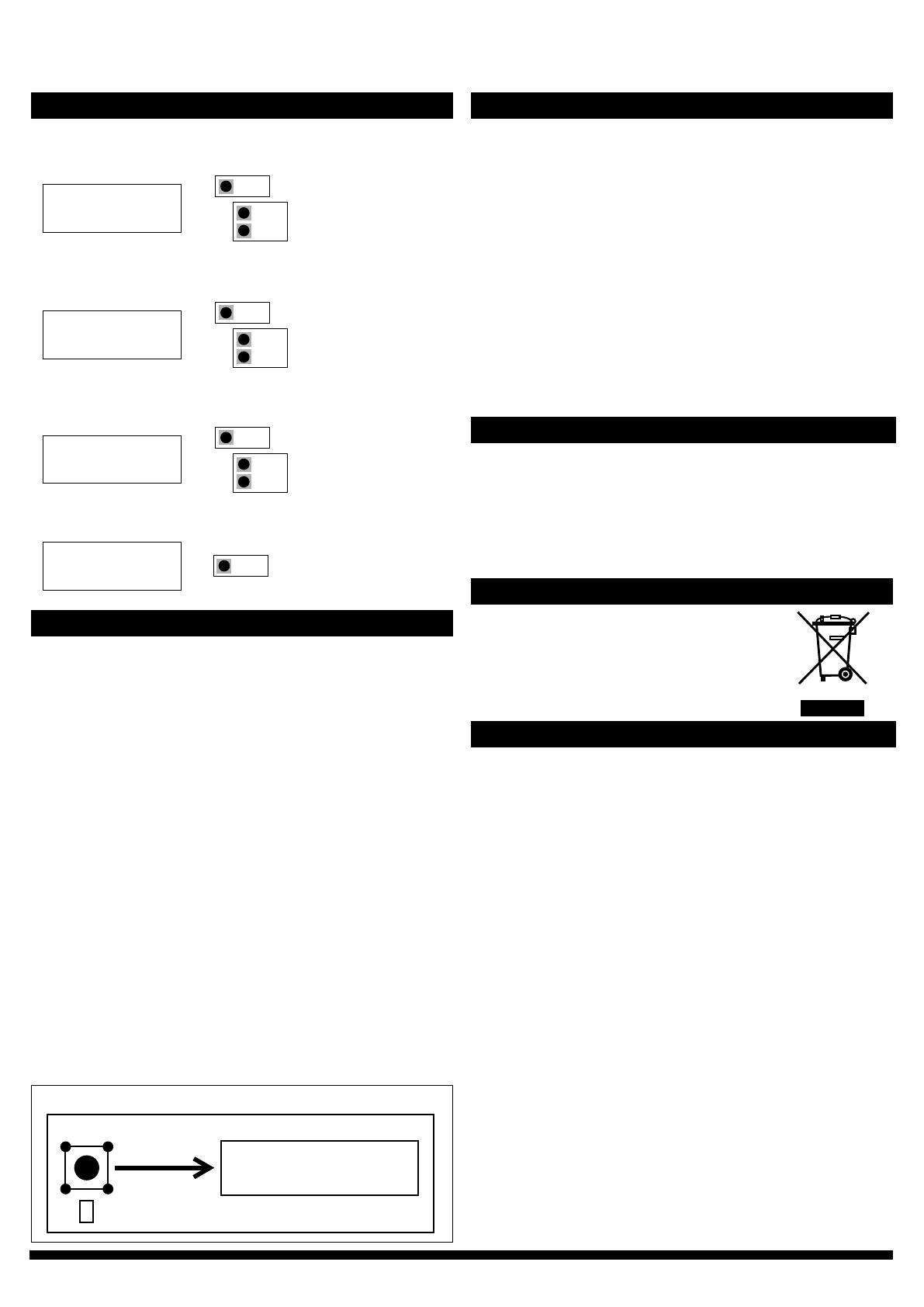
b)PushdownthezerobuonunltheLEDlight(red)turnsonand
thedisplayreads“zeroing”(displayopononly).(seegure4)
c)Thezeroingofthedevicewillproceedautomacally.Zeroingis
completewhentheLEDturnso,andthedisplayreads0(display
opononly).
d)ReinstallthepressuretubesensuringthattheHighpressuretube
isconnectedtotheportlabeled+,andtheLowpressuretubeis
connectedtotheportlabeled−.
Thesellerisobligatedtoprovideawarrantyofveyearsforthedeliv-
eredgoodsregardingmaterialandmanufacturing.Thewarrantyperiod
isconsideredtostartonthedeliverydateoftheproduct.Ifadefect
inrawmaterialsoraproduconawisfound,thesellerisobligated,
whentheproductissenttothesellerwithoutdelayorbeforeexpira-
onofthewarranty,toamendthemistakeathis/herdiscreoneither
by repairing the defecve product or by delivering free of charge to
thebuyeranewawlessproductandsendingittothebuyer.Delivery
costsfortherepairunderwarrantywillbepaidbythebuyerandthe
return costs by the seller. The warranty does not comprise damages
causedbyaccident,lightning,oodorothernaturalphenomenon,nor-
malwearandtear,improperorcarelesshandling,abnormaluse,over-
loading,improperstorage,incorrectcareorreconstrucon,orchanges
and installaon work notdone bytheseller.The seleconofmateri-
alsfordevicespronetocorrosionisthe buyer’sresponsibility,unless
otherwise is legally agreed upon. Should the manufacturer alter the
structureofthedevice,thesellerisnotobligatedtomakecomparable
changestodevicesalreadypurchased.Appealingforwarrantyrequires
thatthebuyerhascorrectlyfullledhis/herduesarisenfromthede-
liveryandstatedinthecontract.Thesellerwillgiveanewwarrantyfor
goodsthathavebeenreplacedorrepairedwithinthewarranty,how-
everonlytotheexpiraonoftheoriginalproduct’swarrantyme.The
warrantyincludestherepairofadefecvepartordevice,orifneeded,
anewpartordevice,butnotinstallaonorexchangecosts.Underno
circumstanceisthesellerliablefordamagescompensaonforindirect
damage.
2)Autozerocalibraon
If the device includes the oponal autozero circuit, no acon is re-
quired.
Autozero calibraon (-AZ) isanautozerofunconinthe form ofan
automaczeroingcircuitbuiltintothePCBboard.Theautozerocali-
braon electronically adjusts the transmier zero at predetermined
me intervals(every10 minutes).The funcon eliminatesalloutput
signaldriduetothermal,electronicormechanicaleects,aswellas
theneedfortechnicianstoremovehighandlowpressuretubeswhen
performing inial or periodic transmier zero point calibraon. The
autozeroadjustmenttakes4secondsaerwhichthedevicereturnsto
itsnormalmeasuringmode.Duringthe4secondadjustmentperiod,
theoutputanddisplayvalueswillfreezetothelatestmeasuredvalue.
Transmiers equipped with the autozero calibraon are virtually
maintenancefree.
a) Disconnect both pressure tubes from the pressure ports labeled
+ and –.
b) Push down the zero button (joystick) until the LED light (red)
turns on and the display reads “zeroing” (display option only). (see
Figure 6)
c) The zeroing of the device will proceed automatically. Zeroing is
complete when the LED turns off, and the display reads 0 (display
option only).
d) Reinstall the pressure tubes, ensuring the High pressure tube is
connected to the port labeled +, and the Low pressure tube is
connected to the port labeled −.
Press down buon
LED turns ON
Display reads “Zeroing”
LED
Figure 4
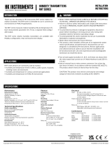
ZEROING THE DEVICE CONTINUED
SELECT
EXIT MENU SELECT
11)Pushselectbuontoexitmenu.
CONFIGURATION CONTINUED
8)Selectproporonalbandaccordingtoyourapplicaon
specicaons.
P-VALUE
206
SELECT
UP
DOWN
9)Selectintegralgainaccordingtoyourapplicaon
specicaons.
I-VALUE
4.00
SELECT
UP
DOWN
10)Selectderivaonmeaccordingtoyourapplicaon
specicaons.
D-VALUE
1.00
SELECT
UP
DOWN
STEP 4: ZEROING THE DEVICE
WARRANTY POLICY
RECYCLING/DISPOSAL
The parts le over from installaon should be
recycled according to your local instrucons.
Decommissioned devices should be taken to a
recyclingsitethatspecializesinelectronicwaste.
Thelidofthedevicehastobeclosedwhentheoperaontemperature
isbelow0°C.Thedisplayneeds15minutestowarmupifthedevice
isstartedintemperaturebelow0°C.
NOTE!Thepowerconsumponrisesandtherecanbeanaddional
errorof0,015voltswhentheoperaontemperatureisbelow0°C.
-40C MODEL: OPERATION IN COLD ENVIRONMENT