Page is loading ...

Copyright HK Instruments 2020 www.hkinstruments. Installaon version 7.0 2020
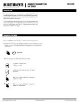
INSTALLATION
INSTRUCTIONS
DIFFERENTIAL PRESSURE TRANSMITTERS
DPT-MOD Series
• READ THESE INSTRUCTIONS CAREFULLY BEFORE
ATTEMPTING TO INSTALL, OPERATE OR SERVICE THIS
DEVICE.
• Failuretoobservesafetyinformaonandcomplywith
instruconscanresultinPERSONALINJURY,DEATHAND/OR
PROPERTY DAMAGE.
• Toavoidelectricalshockordamagetoequipment,disconnect
powerbeforeinstallingorservicinganduseonlywiringwith
insulaonratedforfulldeviceoperangvoltage.
• Toavoidpotenalreand/orexplosiondonotuseinpotenally
ammableorexplosiveatmospheres.
• Retaintheseinstruconsforfuturereference.
• Thisproduct,wheninstalled,willbepartofanengineered
systemwhosespecicaonsandperformancecharacteriscs
arenotdesignedorcontrolledbyHKInstruments.Review
applicaonsandnaonalandlocalcodestoassurethatthe
installaonwillbefunconalandsafe.Useonlyexperiencedand
knowledgeabletechnicianstoinstallthisdevice.
ThankyouforchoosinganHKInstrumentsDPT-MODseriesdier-
enalpressuretransmier.TheDPT-MODseriesisintendedforuse
incommercialenvironments.DPT-MODisamulfunconaltrans-
mierformeasuringvolumeow,velocity,andstacanddieren-
alpressure.Themeasurementscanbereadandtheconguraon
done via Modbus communicaon. DPT-MOD requires less wiring
than the tradional 3-wire transmiers because mulple devices
can be connected on serial line. DPT-MOD can also be used with
several dierent measurement probes such as FloXact™ or pitot
tube,andairdampers.
The DPT-MOD series is comprised of DPT-MOD-2500 and DPT-
MOD-7000 with measurement ranges of -250...2500 Pa and
-250...7000Parespecvely.Allmodelscome withdisplayand op-
onalautozerocalibraon.
DPT-MODseriesdevicesarecommonlyusedinHVAC/Rsystemsfor:
•fan,blowerandltermonitoring
•pressureandowmonitoring
•valveanddampercontrol
•pressuremonitoringincleanrooms
•airowmonitoringacrosscentrifugalfansandblowers
•in-ductairoworpressuremonitoring
•measuringairoworpressureinVAVapplicaons
SPECIFICATIONS
Performance
Accuracy (at applied pressure):
Model2500:
Pressure<125Pa=1%+±2Pa
Pressure>125Pa=1%+±1Pa
Model7000:
Pressure<125Pa=1.5%+±2Pa
Pressure>125Pa=1.5%+±1Pa
(Accuracyspecicaonsinclude:generalaccuracy,
linearity,hysteresis,longterm
stability,andrepeonerror)
Overpressure:
Proofpressure:25kPa
Burstpressure:30kPa
Zero point calibraon:
Automacautozero,manualpushbuonorviaModbus
register
Response me:
1.0−20s,selectableviamenuorviaModbusregister
Communicaon
Protocol:MODBUSoverSerialLine
TransmissionMode:RTU
Interface:RS485
Byteformat(11bits)inRTUmode:
CodingSystem:8-bitbinary
BitsperByte:
1 start bit
8databits,leastsignicantbitsent
rst
1bitforparity
1stopbit
Baudrate:selectableinconguraon
Modbusaddress:1−247addressesselectablein
conguraonmenu
Technical Specicaons
Media compability:
Dryairornon-aggressivegases
Pressure units (select via menu):
Pa,kPa,mbar,inWC,mmWC
Flow units (select via menu):
Volume:m3/s,m3/hr,cfm,l/s
Velocity:m/s,/min
Measuring element:
MEMS,noow-through
Environment:
Operangtemperature:-20...50°C,
-40Cmodels:-40...50°C
Modelswithautozerocalibraon:-5...50°C
Temperaturecompensatedrange0...50°C
Storagetemperature:-40...70°C
Humidity:0to95%rH,noncondensing
Physical
Dimensions:
Case:90.0x95.0x36.0mm
Weight:
150g
Mounng:
2each4.3mmscrewholes,onesloed
Materials:
Case:ABS
Lid:PC
Ductconnectors:ABS
Tubing:PVC
Protecon standard:
IP54
Display
2-linedisplay(12characters/line)
Line1:Volumeorvelocitymeasurement
Line2:Pressuremeasurement
Size:46.0x14.5mm
Electrical connecons:
4-screwterminalblock
Wire:0.2–1.5mm2(12–24AWG)
Cable entry:
Strainrelief:M16
Knockout:16mm
Pressure ngs
Maleø5.0mmand6.3mm
Electrical
Supply voltage:
24VACorVDC±10%
Power consumpon:
<1.3W
Output signal:
viaModbus
Conformance
MeetsrequirementsforCEmarking:
EMCDirecve2014/30/EU
RoHSDirecve2011/65/EU
WEEEDirecve2012/19/EU
APPLICATIONS
INTRODUCTION WARNING
COMPANY WITH
MANAGEMENT SYSTEM
CERTIFIED BY DNV GL
= ISO 9001 = ISO 14001 =
RoHS 2
2011/65/EU

Copyright HK Instruments 2020 www.hkinstruments. Installaon version 7.0 2020
SCHEMATICS
DIMENSIONAL DRAWINGS
Figure 1a - Surface mounng
MOUNTING THE DEVICE CONTINUED
Figure 1b - Mounng orientaon
Figure 1c - Applicaon connecons
Connecon for display
Terminal block
Pressure
sensor
Menu buons
LED
SELECT
UP
DOWN
ZERO
B
A
24 V
GND
90.0
77.0
71.5
53.0
4.2
95.0
36.0
DPT
Thepressuretubesareconnectedtoaowmeasurementprobe(i.e.FloXact),ortothe
measurementportsspeciedbythefanmanufacturer.PleaseseetheFloXactinstallaon
guideorthefanmanufacturer’stechnicalspecicaonsformoreinformaon.
YES NO NO
INSTALLATION
1)Mountthedeviceinthedesiredlocaon(seestep1).
2)Openthelidandroutethecablethroughthestrainreliefand
connectthewirestotheterminalblock(s)(seestep2).
3)Thedeviceisnowreadyforconguraon.
WARNING!Applypoweronlyaerthedeviceisproperlywired.
STEP 2: WIRING DIAGRAMS
ForCEcompliance,aproperlygroundedshieldingcableisrequired.
1)Unscrewthestrainreliefandroutethecable.
2)Connectthewiresasshowningure2.
3)Tightenthestrainrelief.
Figure 2 - Wiring diagram
B
A
24 V
GND
+ Power supply
24 VDC / 24 VAC
Modbus
STEP 1: MOUNTING THE DEVICE
1)Selectthemounnglocaon(duct,wall,panel).
2)Usethedeviceasatemplateandmarkthescrewholes.
3)Mountwithappropriatescrews.
Pressure
Flow
Static pressure Filter/Damper
monitoring
Fan/Blower
monitoring
Not
connected

Copyright HK Instruments 2020 www.hkinstruments. Installaon version 7.0 2020
CONFIGURATION CONTINUED
STEP 3: CONFIGURATION
3)If
Commonprobe
selected:selectmeasurementunitsusedinthe
formula(akaFormulaunit)(i.e.l/s)
NOTE:Theowunit
none
isselectedbydefaultandthedisplay
showsonlythepressurereading.
1)AcvatethedeviceMenubypushingthetheselectbuon
for2seconds
2)Selectthefunconingmodeoftheowmeter:
-Select
Manufacturer
whenconnecngDPT-MODtoafan
withpressuremeasurementpoints
-Select
Commonprobe
whenusingDPT-MODwithacommon
measurmentprobethatfollowstheformula:
q=k∙√∆P
(i.e.FloXact)
MANUFACTURER
Common probe
SELECT
UP
DOWN
Common probe Flakt Woods
SELECT
UP
DOWN
FORMULA UNIT
l/s
SELECT
UP
DOWN
4)SelectK-value
a.Ifmanufacturerselectedinstep1:
EachfanhasaspecicK-value.SelecttheK-valuefromfanmanufac-
turer’sspecicaons.
Manufacturer: K-value:
Fläktwoods k=0,3...99
Rosenberg k=37...800
Nicotra k=10...1500
Comefri k=10...2000
Ziehl k=10...1500
Ebm-papst k=10...1500
Gebhardt k=50...4700
7)Responseme:Selectresponsemebetween1.0–20s.
RESPONSE TIME
20 s
SELECT
UP
DOWN
11)Pushselectbuontosavechangesandtoexitmenu.
SELECT
EXIT MENU
SELECT
b. If
Commonprobe
selectedinstep1:
Each common probe has a specic K-value. Select the K-value from
commonprobemanufacturer’sspecicaons.
AvailableK-valuerange:0.001...9999.000.
K-VALUE
9000.000
SELECT
UP
DOWN
8)SelecttheaddressforModbus:1...247.
9)Selectthebaudrate:9600/19200/38400.
ADDRESS
99
SELECT
UP
DOWN
BAUD RATE
9600
SELECT
UP
DOWN
10)Selecttheparitybit:None/Even/Odd.
PARITY BIT
NONE
SELECT
UP
DOWN
STEP 4: ZEROING THE DEVICE
NOTE! Always zero the device before use.
Tozerothedevicethreeoponsareavailable:
1)ManualPushbuonzeropointcalibraon
2)Autozerocalibraon
3)ViaModbusregister
Doesmytransmierhaveanautozerocalibraon?Seetheproductla-
bel.Ifitshows-AZinthemodelnumber,thenyouhavetheautozero
calibraon.
1)ManualPushbuonzeropointcalibraon
NOTE: Supply voltage must be connected at least one hour prior to
zeropointadjustment.
a)Disconnectbothpressuretubesfromthepressureportslabeled+
and–.
b)PushdownthezerobuonunltheLEDlight(red)turnsonandthe
displayreads“zeroing”(displayopononly).(seegure3)
c)Thezeroingofthedevicewillproceedautomacally.Zeroingis
completewhentheLEDturnso,andthedisplayreads0(display
opononly).
d)ReinstallthepressuretubesensuringthattheHighpressuretube
isconnectedtotheportlabeled+,andtheLowpressuretubeis
connectedtotheportlabeled−.
6)Selectowunitfordisplay:
Flowvolume:m3/s,m3/h,cfm,l/s,none(default)
Velocity:m/s,f/min,none
5)Selectpressureunitfordisplay:Pa,kPa,mbar,inWC,mmWCor
none.
PRESS.UNIT
Pa
SELECT
UP
DOWN
FLOW UNIT
m3/s
SELECT
UP
DOWN

Copyright HK Instruments 2020 www.hkinstruments. Installaon version 7.0 2020
Thesellerisobligatedtoprovideawarrantyofveyearsforthedelivered
goodsregardingmaterialandmanufacturing.Thewarrantyperiodiscon-
sideredtostartonthedeliverydateoftheproduct.Ifadefectinrawmate-
rialsoraproduconawisfound,thesellerisobligated,whentheproduct
issenttothesellerwithoutdelayorbeforeexpiraonofthewarranty,to
amend themistakeathis/herdiscreoneitherbyrepairingthedefecve
productorbydeliveringfreeofchargetothebuyeranewawlessproduct
andsendingittothebuyer.Deliverycostsfortherepairunder warranty
willbepaidbythebuyerandthereturncostsbytheseller.Thewarranty
does notcomprisedamages causedby accident, lightning,oodor other
naturalphenomenon,normalwearandtear,improperorcarelesshandling,
abnormaluse,overloading,improperstorage,incorrectcareorreconstruc-
on, or changes and installaon work not done by the seller or his/her
authorizedrepresentave.Theseleconofmaterialsfordevicesproneto
corrosion is the buyer’s responsibility, unless otherwise is legally agreed
upon.Shouldthemanufactureralterthestructureofthedevice,theseller
isnotobligatedtomakecomparablechangestodevicesalreadypurchased.
Appealingforwarrantyrequiresthatthebuyerhascorrectlyfullledhis/
herduesarisenfromthedeliveryandstatedinthecontract.Thesellerwill
giveanewwarrantyforgoodsthathavebeenreplacedorrepairedwithin
thewarranty,howeveronlytotheexpiraonoftheoriginalproduct’swar-
rantyme.Thewarrantyincludestherepairofadefecvepartordevice,
orifneeded,anewpartordevice,butnotinstallaonorexchangecosts.
Under no circumstance is the sellerliable for damagescompensaon for
indirectdamage.
2)Autozerocalibraon
If the device includes the oponal autozero circuit, no acon is re-
quired.
Autozero calibraon (-AZ) is an autozero funcon in the form ofan
automaczeroingcircuitbuiltintothePCBboard.Theautozerocali-
braon electronically adjusts the transmier zero at predetermined
me intervals(every10minutes).Thefunconeliminatesalloutput
signaldriduetothermal,electronicormechanicaleects,aswellas
theneedfortechnicianstoremovehighandlowpressuretubeswhen
performing inial or periodic transmier zero point calibraon. The
autozeroadjustmenttakes4secondsaerwhichthedevicereturnsto
itsnormalmeasuringmode.Duringthe4secondadjustmentperiod,
theoutputanddisplayvalueswillfreezetothelatestmeasuredvalue.
Transmiers equipped with the autozero calibraon are virtually
maintenancefree.
3)ViaModbusregister
Makesurethereisnopressureintheductwhenthezeroingisdone
viaModbusregister.
a) Disconnect both pressure tubes from the pressure ports labeled +
and –.
b) Push down the zero buon (joysck) unl the LED light (red)
turns on and the display reads “zeroing” (display opon only). (see
Figure 6)
c) The zeroing of the device will proceed automacally. Zeroing is
complete when the LED turns off, and the display reads 0 (display
opon only).
d) Reinstall the pressure tubes, ensuring the High pressure tube is
connected to the port labeled +, and the Low pressure tube is
connected to the port labeled −.
Press down buon
LED turns ON
Display reads “Zeroing”
LED
Figure 3
ZEROING THE DEVICE CONTINUED
STEP 5: MODBUS REGISTERS
Register Parameter descripon Data Type Value Range
3x0001 Programversion 16bit 0...9900 0,00...99,00
3x0002 Pressurereading 16bit -250...2500/7000 -250...2500/7000Pa
3x0003 Flowm3/s 16bit 0...10000 0...100m3/s
3x0004 Flowm3/h 16bit 0...30000 0...30000m3/h
3x0005 Flowcfm 16bit 0...30000 0...30000cfm
3x0006 Flowl/s 16bit 0...3000 0...3000l/s
3x0007 Velocitym/s 16bit 0...1000 0...100m/s
3x0008 Velocityf/min 16bit 0...5000 0...5000f/min
Funconcode04-Readinputregister
MODBUS REGISTERS CONTINUED
Funconcode06-Writesingleregister
Register Parameter descripon Data Type Value Range
4x0001 Manufacturer 16bit 0...7 0...7
4x0002 Formulaunit(Manufacturer=7) 16bit 0...5
0:m3/s,1:m3/h,2:cfm,3:l/s,
4:m/s,5:f/min
4x0003 K-factorinteger 16bit 0...9999 0...9999
4x0004 K-factordecimal 16bit 0...999 0...999
4x0005 Responseme 16bit 1...20 1...20s
Funconcode16-Writemulpleregisters
Register Parameter descripon Data Type Value Range
4x0001 Manufacturer 16bit 0...7 0...7
4x0002 Formulaunit(Manufacturer=7) 16bit 0...5
0:m3/s,1:m3/h,2:cfm,3:l/s,
4:m/s,5:f/min
4x0003 K-factorinteger 16bit 0...9999 0...9999
4x0004 K-factordecimal 16bit 0...999 0...999
4x0005 Responseme 16bit 1...20 1...20s
Funconcode05-Writesinglecoil
Register Parameter descripon Data Type Value Range
0x0001 Zeropointcalibraon Bit0 0...1 On-O
WARRANTY POLICY
RECYCLING/DISPOSAL
The parts le over from installaon should be
recycled according to your local instrucons.
Decommissioned devices should be taken to a
recyclingsitethatspecializesinelectronicwaste.
Funconcode03-Readinputholdingregister
Register Parameter descripon Data Type Value Range
4x0001 Manufacturer 16bit 0...7 0...7
4x0002 Formulaunit(Manufacturer=7) 16bit 0...5
0:m3/s,1:m3/h,2:cfm,3:l/s,
4:m/s,5:f/min
4x0003 K-factorinteger 16bit 0...9999 0...9999
4x0004 K-factordecimal 16bit 0...999 0...999
4x0005 Responseme 16bit 1...20 1...20s
-40C model: operation in cold environment
Thelidofthedevicehastobeclosedwhentheoperaontemperature
isbelow0°C.Thedisplayneeds15minutestowarmupifthedevice
isstartedintemperaturebelow0°C.
NOTE!Thepowerconsumponrisesandtherecanbeanaddional
errorof0,015voltswhentheoperaontemperatureisbelow0°C.
/