Page is loading ...

Page 1 of 5
Johnson Controls Denmark ApS
Christian X's Vej 201 ∙ 8270 Højbjerg ∙ Denmark
Phone +45 87 36 70 00 ∙ www.sabroe.com
CVR No 19 05 61 71
Mounting instruction
011078
13 December 2021
Coupling alignment and fitting
Installation and alignment
In principle, alignment means manoeuvring the motor to make the shaft form an extension of the crankshaft.
Note: Before performing any work on the coupling, make sure that the compressor motor cannot start up
inadvertently.
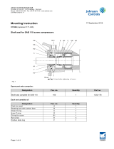
Fig. 1: CFA coupling
a
Y
X
B 1
B 2
A
1
2
C

Page 2 of 5
Johnson Controls Denmark ApS
Christian X's Vej 201 ∙ 8270 Højbjerg ∙ Denmark
Phone +45 87 36 70 00 ∙ www.sabroe.com
CVR No 19 05 61 71
Fig. 2: AMR coupling
Fig. 3: Locking assembly in compressor hub
1
2Y
X
a
B
AC
F
D

Page 3 of 5
Johnson Controls Denmark ApS
Christian X's Vej 201 ∙ 8270 Højbjerg ∙ Denmark
Phone +45 87 36 70 00 ∙ www.sabroe.com
CVR No 19 05 61 71
Compressor Coupling
size
Distance mm Torque Nm
C *
Nominal F A B D
SMC/HPC 104-106-108
SMC/HPC 112-116
TSMC
HPX 704-706-708-712-716
AMR 312 105 0 83 55 83
SMC/HPC 112-116
SMC 108E
HPX 712-716
AMR 350 116 0 83 128 83
SMC/HPC 104
HPX 704
CFA 30
With flywheel 189 4 83 220 83
SMC/HPC 106-108
SMC/HPC 112-116
HPX 706-708-712-716
CFA 30 189 0 83 220 83
SMC/HPC 104-108
SMC 108S
HPX 708
CFA 90
With flywheel 189 4 83 500 83
SMC 106-108L/E-112-116
HPC 106-112-116
HPX 706-712-716
CFA 90 189 0 83 500 83
SMC 108E CFA 140
With flywheel 189 4 83 500 83
SMC/HPC 112-116
HPX 712-716 CFA 140 189 0 83 500 83
SMC 112E-116L/E
HPC 112-116
HPX 716
CFA 200
189 0
83 500 83
164 ** 15.5 **
Table 1
* See final installation
** When tunnel is required and motor shaft length is 210 mm (motor size 355)
Preliminary installation of coupling
All couplings
Never tighten the screws “D” unless the locking assembly is mounted. Otherwise it might damage the locking
system.
• Mount the retaining plate from the coupling screen onto the compressor.
• Carefully clean the motor and compressor hubs and shaft contact surfaces and apply a light oil film. Do not
use any oil with molibdenum bisulphite or high pressure additives and not grease. These substances nota-
bly reduce the friction coefficient.

Page 4 of 5
Johnson Controls Denmark ApS
Christian X's Vej 201 ∙ 8270 Højbjerg ∙ Denmark
Phone +45 87 36 70 00 ∙ www.sabroe.com
CVR No 19 05 61 71
• Insert the locking assembly into the compressor hub bore and slide the assembly onto the compressor
shaft.
• Place the hub at the compressor shaft, observing that the locking assembly is fully inserted in the hub and
aligns the shaft end.
If a flywheel is required for a CFA coupling, the assembly must be placed 4 mm closer to the compressor
measured from the shaft end. See Table 1 and Fig. 3.
• Tighten all screws “D” gradually and regularly in crossed sequence to reach tightening torque 83 Nm.
• Measure the length of the key in the motor shaft and the length of the gripping part of the motor hub.
• Remove half of the difference in length from the key.
• When sliding the hub to obtain distance “C”, check that the key has optimal engagement in the keyway of
the hub.
• Place the motor hub on the motor shaft and slide it fully towards the motor.
• Line up the motor so that the free holes in the motor feet are right above the threaded holes in the base
frame.
AMR couplings
• Assemble the intermediate piece and the lamella segments with the 8 screws, applying the prescribed tor-
que “B”. Remember the shaped washers facing the lamellas.
• Insert the coupling intermediate piece. The intermediate piece should only be secured to the compres-
sor flange. Do not insert the last four screws in the motor flange until the coupling has been aligned.
As the compressor shaft rotates during the alignment procedure, the motor must turn with it, as the screws
in the intermediate piece engage in the free holes in the motor hub flange.
• Slide the motor coupling flange to make up distance “C”. See Table 1.
• Attach the motor hub with the 2 mounting screws by tightening them a little at a time to ‘Torque A’ in Table 1.
• Tighten the measuring pin on the coupling flange of the compressor as shown in Fig. 2: AMR coupling.
CFA couplings
• Secure the motor by inserting and tightening the motor bolts.
• If a flywheel is to be fitted, carefully clean the compressor hubs and flywheels contact surfaces and apply a
light oil film. Insert the guiding edge in the centre of the flywheel in the centre bore of the compressor hub
and align the holes in the two parts.
• Check distance “C” between the compressor hub/flywheel surface and the motor shaft. If the distance is
more than 2 mm out of range,adjust it by moving the motor.
• Insert the pin bolts “B1” in the threaded holes in both hubs and tighten them with a standard Allen key. De-
pending on the size of coupling there will be 3 (size CFA30 and CFA90) or 4 (size CFA140 and CFA200).
When a CFA140 or CFA200 coupling is to be fitted insert only 3 of the 4 pin bolts in the compressor
hub. If there are more threaded holes than needed in the hub choose a pattern that distributes the pin bolts
even.
• Tighten the pin bolts to the recommended torque “B” (see Table 1) using a torque wrench. Make counter
hold by blocking the shafts rotation with an iron bar on two other pinbolts.
• Grease the pin bolts with copper grease (1231.333 - 500 g in a can or 1231.334 - 100 g in a tube).

Page 5 of 5
Johnson Controls Denmark ApS
Christian X's Vej 201 ∙ 8270 Højbjerg ∙ Denmark
Phone +45 87 36 70 00 ∙ www.sabroe.com
CVR No 19 05 61 71
• Insert the first rubber part on the motor hub by sliding it on to the pin bolts. The metal surfaces of the rubber
part (with chamfered edges of the mounting holes) are to mate the hub surface.
• Insert the intermediate piece together with the second rubber part and slide the rubber part on to the pin
bolts, with the metal surfaces (with chamfered edges of the mounting holes) facing the compressor hub. In
case of fitting a CFA140 or CFA200 coupling insert the last pin bolt and tighten it to the recommended tor-
que “B”.
• Place the motor hub at a distance “C” from the compressor hub and fixate it by tightening the two mounting
bolts gradually to torque “A”. See Table 1.
• Grease the contact surfaces of the radial bolts. Avoid greasing the blue part of the threads.
• Insert all radial bolts and tighten them with a standard Allen key until the contact surfaces mate the inter-
mediate piece properly.
• Tighten the radial bolts to torque “B” (see Table 1) using a torque wrench. Make sure that the rubber parts
are not twisting.
Fig. 4
• Mount the measuring pin on the coupling flange of the compressor as shown in Fig. 1.
The pin bolts “B1” and radial bolts “B2” connecting the rubber element to the intermediate piece must be tightened to
the torque given in Table 1. Use a torque wrench.
Tightening “by feel” will not do. Experience has proved that the tightening torque in such cases is far too low. If tight-
ening torque is too low it will inevitably lead to slackening of the bolts in service and consequently to the destruction
of the coupling.
Make sure that when tightening the radial bolts, the aluminium bushes in the rubber part are not twisted, but sit
straight.
It is particularly important to prevent twisting of the rubber part during tightening of the radial bolts, otherwise the
cylindrical faces between aluminium insert and the intermediate piece will not engage on the full area, but only on
two corners. This will inevitably lead to slackening of the screws and consequently to the destruction of the coupling.
Erhardt Nielsen
Manager, Compressor Development
Technical Support and Development
Direct no.: +45 87 36 77 20
Fax no.: +45 87 36 77 05
E-mail: [email protected]
Correct
Incorrectradial radial
/