Gianni Industries RTS-700 Installation guide
- Category
- Security device components
- Type
- Installation guide

Copyright
©
All Rights Reserved. P-MU-RTS-700-800 Published: 2020.06.05
Specifications
Operating Voltage:12~24VDC
Current Draw: Pull in 40mA/12VDC; Holding 30mA/12VDC
Sensor Range: 1”~6” (3~15cm) (±10%)
Relay Rating: 1A/30VDC maximum
Operating Temperature: -10~+70ºC
Ambient Humidity: 5~95%
Dual LED, illuminated sensor indicates status:
Standby (Red), Active (Green)
Output Time: 0.5~20 seconds, toggle
*Toggle: turn all the way clockwise
Faceplate Finish: Stainless steel
Pull in 50mA/24VDC; Holding 25mA/24VDC
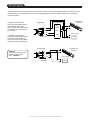
Adjusting Sensor Range & Trigger Time
5 PIN
Trigger time
(door opening time)
adjustment
Note: Adjusting door opening time to maximum
(turning all the way to the right) will set the switch
to toggle mode.
Sensor range
adjustment
FarNear Short Long
RTS Series Wave Sense Infrared Exit Devices
Installation Instructions
RTS-700
RTS-800
RTS-8585
3.37”
(85.5mm)
2.36”
(60mm)
3.37”
(85.5mm)
2.74”
(69.5mm)
3.29”
(83.5mm)
4.49”
(114mm)
3.46”
(88mm)
3.46”
(88mm)
Side View
11.81”
(300mm)
1.38”
(Ø35mm)
0.83”
(21mm)
0.16”
(4mm)
Black
Red
Yellow
Green
Blue
(-)
(+)
(N.C.)
(COM.)
(N.O.)
0.73”
(18.5mm)
Side View
0.08”
(2mm)
11.81”
(300mm)
1.38”
(Ø35mm)
Black
Red
Yellow
Green
Blue
(-)
(+)
(N.C.)
(COM.)
(N.O.)
0.24”
(6mm)
0.1”
(2.5mm)
Side View
Black
Red
Yellow
Green
Blue
(-)
(+)
(N.C.)
(COM.)
(N.O.)
11.81”
(300mm)
0.87”
(Ø22mm)
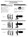
RTS-700/800/8585

Wiring Diagrams
The RTS series wave sense infrared exit device includes one set of output contacts NC/NO/COM. It can directly control
electrical devices (e.g. electrified locks) or works with digital keypads or proximity readers. Please refer to the wiring
instructions below.
In Figure A, the RTS series
connects to the Request-to-Exit
input terminal of the access
control system. Relay output time
can be reduced to a minimum of
0.5 seconds.
In Figure B, the RTS series
controls a fail-safe locking device.
If it controls a fail-secure lock,
connect to the NO contact. Relay
output time is door opening time.
Caution:
【Figure A】
Keypad
Proximity Reader
Power Supply
12VDC
Electrified Lock
(Fail-safe)
N.O.
COM.
N.C.
PB
Side View
Black(-)
Red(+)
Yellow (N.C.)
Green(COM.)
Blue(N.O.)
Power Supply
12VDC
Electrified Lock
(Fail-safe)
Side View
Black(-)
Red(+)
Yellow(N.C.)
Green(COM.)
Blue(N.O.)
【Figure B】
To avoid wire burning, do not
exceed maximum relay
rating: 1A/30VDC.
Copyright
©
All Rights Reserved. P-MU-RTS-700-800 Published: 2020.06.05
-
 1
1
-
 2
2


Gianni Industries RTS-700 Installation guide
- Category
- Security device components
- Type
- Installation guide
Ask a question and I''ll find the answer in the document
Finding information in a document is now easier with AI
Related papers
-
Gianni Industries RTS-500 Installation guide
-
Gianni Industries DG-ea300 Installation guide
-
Gianni Industries PBA-860/860DE Installation guide
-
-
-
Gianni Industries GL600-S Installation guide
-
-
Gianni Industries DG-120 Installation guide
-
Gianni Industries GML800 Installation guide
-
Other documents
-
Zebra 8585/8595 User guide
-
BEA R2E-100 User guide
-
SECO-LARM SK-2612-SPQ Owner's manual
-
 SECO-LARM USA Enforcer Access SD-962AR-36A User manual
-
SECO-LARM CS-PD419-PQ Infrared Proximity Sensors User manual
-
Legrand Emergency Shunt Relay Installation guide
-
 ENFORCER SK-1131-SPQ User manual
-
 ACS CFSound-IV User manual
-
 Riva RTS650 Installation guide
-


