Page is loading ...

KH500DE Delayed Egress Electromagnetic Lock
(Key Hole Mounting)
Installation Instructions
Overview
The KH500DE Delayed Egress Electromagnetic Lock with Key Hole Mounting is designed to comply with the NFPA 101
Life Safety Code. This delayed egress locking system’s principal application is for secure locking and delayed release of
perimeter and emergency exit doors. The KH500DE is a self-contained, standalone unit that uses existing door exit and
latching hardware, and all electronics are built into the magnet’s wiring compartment for ease of installation.
3/16"
Screw Package Components:
x 1
x 1
x 2
x 6 x 2
Allen Flat Head Screw
5/16"x 1 3/8"
Guide Pin
3/16" x 5/8"
Hexagon Key (Allen Wrench) Rubber Washer
11/32" x 19/32" x 5/32"
Phillips Flat Head Screw
3/16" x 1 1/4"
Thru-Bolt (Hex Screw)
1/4" x 1 9/16"
Metal Washer
x 35/16" x 7/8"
x 1
Sexnut Bolt
x 1 1/2" x 1 9/16"
Armature Screw
Armature Plate
Guide Pin
Sexnut Bolt
Rubber Washer
Metal Washer
Electromagnet
Mounting Bolt
Self-Tapping Screw
Mounting Plate
10 1/2” (267mm)
Dimensions
Specifications
Current draw
(Standalone operation)
500mA / 12VDC
Current draw
(With optional slave lock)
1000mA / 12VDC
Alarm relay output
1A / 24VDC
Input voltage
Auto select 12/ 24VDC +- 10%
Copyright Gianni Industries.Inc. All Rights Reserved.
P-MU-KH500DE Published: 2019.05.14
1
250mA / 24VDC
500mA / 24VDC
(Maximum)
Holding force 1200 lbs
Finish Anodized aluminum (US28)
Buzzer Hole
1/4” (6mm)
1 9/16” (40mm)
10 1/2” (267mm)
2 5/8” (67mm)
1 9/16” (40mm)
2 3/8” (61mm)
7 1/4” (185mm)
5/8” (16mm)
Internal buzzer
LED indication
95 dB
Green: Armed (exit delay)
Red: Disarmed (free egress)

How it Works
Copyright Gianni Industries.Inc. All Rights Reserved.
P-MU-KH500DE Published : 2019.05.14
2
The delayed egress system is activated by pushing on the exit push bar. The exit attempt (pushing on the exit bar) must
exceed a pre-set nuisance delay of 0, 1, 2 or 3 seconds to start the delayed egress cycle. Note: the 0 second nuisance
includes a 200 millisecond de-bounce delay to eliminate false triggering.
When the nuisance time is exceeded after applying a continuous pressure of 15 pounds or greater to the exit bar, an
irreversible 15 or 30 second egress cycle begins. During this egress cycle, a piezo alarm beeps once for each second of the
count-down. When the magnetic lock de-energizes to release the door for free egress after the delayed egress cycle, the piezo
alarm sounds continuously and the door remains unlocked until reset.
Use the push bar with power transfer door loop. All
wiring must be protected or concealed in compliance
with local codes. Install and wire the push bar per the
manufacturer’s instructions. Use the armored, flexible
door loop for routing the wiring from the bar’s
microswitches into the hollow door frame.
INSTALLATION OF THE PUSH BAR
*Handling Caution:
The KH500DE contains sensitive electronic components and therefore must not be dropped or abused. The circuit
components are also subject to damage from high static electricity discharges and must be handled with care,
especially in dry climates and in winter months. As a normal procedure during installation and adjustments, installers
should always discharge themselves through a good earth before touching the lock assembly or its wires. Failure to
comply with recommended procedures may result in damage to the lock and could void system warranty.

2. Ensure that the 12 VDC power supply is off and connect the "V+" and "V-" terminals.
3. Connect a normally open single pole momentary switch to the “START” and “F/COM” terminals in the lock’s wiring
compartment. This simulated the exit bar’s micro switch.
Note: Make sure the power supply is still off; place the armature (strike) plate on the magnet face and ensure that the plate is
aligned properly.
Egress Test
1.Momentarily depress the exit bar switch (at least 200 msec and then release) to simulate an egress attempt. The sounder
will start beeping once per second and the blinking LED will change to solid green to indicate an egress cycle has been
initiated.
2. After 15 beeps the magnet will release the armature plate. The LED will change to solid RED and the sounder will
give a continuous alarm to indicate that the egress cycle is complete and that the lock will remain in the free egress
alarm state until it is reset.
3.Momentarily activate the reset switch. The sounder will beep, the magnet will energize and the green LED will return to
blinking once per second, indicating normal armed operation.
Fire Emergency Test
1. To simulate a fire emergency, press the normally open switch you installed in Test Set-up between the “FIRE” and
“ F/COM” terminals. The lock will release immediately and sound.
Bond Test
1. Place a business card at each end of the magnet between armature plate and magnet.
2. Apply DC power. After a 3 second delay, the bond alarm will sound a repeating pattern of 4 quick beeps, synchronous with
the flashing LED.
Reset Test
1. Connect a normally closed switch in series with the power supply and the lock’s “ V+” input terminal. Momentarily opening
the switch will provide a reset.
2. Place a normally open switch across “RST” and “F/COM” terminals. Momentarily closing the switch will provide a reset.
Start-up Test
Turn on (or plug in) the power. The lock should beep once on power-up. The green LED should blink once per second.
Two reset methods can be used:
Bench Testing
This procedure allows the installer to perform a quick bench check of the KH500DE lock and to become familiar with the
lock’s basic operation prior to installation.
Test Set-up
Remove the cover plate and locate the 4-position DIP-switch on the bottom circuit board. Set all 4 switches to OFF. The lock
is now set for 0.2 second nuisance delay time (which requires a 0.2 second minimum bar press) and is set for 15 second
delayed egress cycle. Proceed to wire the magnetic lock as follows:
1. In the lock’s wiring compartment, place a a normally open switch across “FIRE” and “F/COM”.
Copyright Gianni Industries.Inc. All Rights Reserved.
P-MU-KH500DE Published : 2019.05.14
3
2. Release the normally open switch between the “FIRE” and “ F/COM” terminals. The lock will release immediately and
sound.
Note
: When all the testing is complete, remove all wiring connections to the lock’s terminals.

Magnetic Lock Installation for Outswing Doors
Note what type door frame header is in place and install filler plate or angle bracket as necessary. The lock must be installed
on the interior, secure side of an outward swinging door, opposite the hinges and clear of any closing hardware. The door
must be correctly aligned, free of mechanical binding and should close firmly against the door stop.
1
Template
Power
4
Rubber Washer
5
6
7
9
Connect the power and test the
holding force. Add washers if
there is still a gap between the
magnet and armature plate.
Outswing Door
Find the paper installation template
included with the magnet (you will
need this).
Fold it on the dotted line.
2
Place the folded template in the
proper position on the door/jamb
and mark the holes you will cut for
your magnet and armature plate.
(Using tape will help)
3
Drill the holes according to the marks
you made.
(Check Twice! Drill Once!)..
Attaching Magnet to Mounting Plate
The rubber washer helps the
armature plate to pivot. As it
should NOT be tightened all the
way to door.
Attach the mounting plate to the
jamb and tighten the mounting
screws.
Pass the wiring through the
mounting plate and into the
wiring hole at the top of the
magnet and into the PCB
area.
Attach the magnet to the
mounting plate. Use the
Allen wrench and thru-bolts
to tighten the magnet to the
mounting plate.
Copyright Gianni Industries.Inc. All Rights Reserved.
P-MU-KH500DE Published : 2019.05.14
4
Power Wires
Allen wrench
1/2” 5/16”
1 7/16”
Solid Door
Hollow Metal Door
Armature Plate
Install the armature plate as
shown in the drawing to the left.
The actual dimensions of the
holes are illustrated below.
1/2” 5/16”
Drill a 5/16” (8mm) hole through the door for the armature side.
For the sexnut side (secure side), enlarge the hole to
1/2” (12.7mm) for the width of the sexnut.
On wood doors the depth of the sexnut is 1 7/16” (36mm).
1. Align the two slotted holes and attach the magnet to the
mounting plate.
Keyhole Mounting “slides Left to Right”
2. Slide the magnet onto the mounting plate.
Key Hole

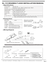
Wiring the Lock
Single Door Installation
PC Board Terminal Connection
F/COM
FIRE
START
RST
PASS
N.O.
N.C.
R/COM
V+
V-
Ground
Emergency signal input
Activation input
(Switch signal triggers PC board)
Reset input (Key switch)
Connection to keypad or reader
without sounder
Relay output (for external alarm)
Rating: 1A/24VDC, 0.5A/125VAC
12/24 VDC (Automatic selection)
Copyright Gianni Industries.Inc. All Rights Reserved.
P-MU-KH500DE Published : 2019.05.14
5
1. All wiring must be fed through the ½” access hole previously drilled into the header.
2. The magnet is a low voltage device (NEC class 2) and can be powered by a 12 Volt DC power supply rated at 1.0 amps or
greater. Use 18 AWG gauge wire. The power wire run should not exceed 75 feet. Observe polarity and connect the DC
power supply to "V+" and "V-" terminals.
3. Directly connect two leads from the normally open or closed dry contacts in the supervised Fire Alarm Control Panel (FACP)
or other fire emergency system to the “FIRE” and “F/COM” terminals. Wire runs should not excced 1,500 feet. Use a
minimum of 18 AWG gauge wire.
4. Directly connect the WHITE wire from the push bar to the “START” terminal and the BLACK wire from the push bar to the
“F/COM” terminal.
5. Reset of the system can be done in two ways:
A. connect a normally closed Form A contact switching device in series with the plus 12 volt DC power connection to
terminal “V+.”
B. connect a normally open Form A contact switching device to terminals “RST” and“F/COM”. Actuation of the momentary
switch will result in a reset.
Connecting Optional Control and Remote Monitoring Devices
1. Form A dry relay contacts are provided for remote monitoring of the locking status. Whenever an alarm signal occurs due to a
bonding violation, egress cycle or fire emergency, the output relay contacts across “R/COM ” "N.O." and "N.C. will change
status. Contacts are rated 1 amp at 24 VDC.
2. A proximity keypad/reader or momentary switch with normally open contacts can be installed to provide a manually
controlled bypass for free egress. A contact closure across “PASS” and “F/COM” will release the lock for the duration of the
maintained closure. During bypass, the LED will switch to red and will return to green when bypass is complete. The lock
will also beep when the bypass is completed.
3. For 2-door (double door) operation, install a KH500 series lock on the adjacent door and connect it to terminals “V+” and
V-”. This slave lock will follow the operation of the master lock.
Terminal Description
F/COM
FIRE
START
RST
PASS
R/COM
V+
V-
N.O.
N.C.
COM
N.O.
COM
N.O.
COM
N.O.
COM
N.O.
INSIDE
CP-32
INSIDE
PBA-860
INSIDE
KS-750-S-C
INSIDE
DG-185
OUTSIDE
INSIDE
ALARM
12VDC POWER SUPPLY
(Door Pull /Fire panel system)
EMERGENCY
RELEASE
CALL POINT
PUSH BAR
KEY SWITCH
DIGITAL
KEYPAD

DIP Switch Settings
Nuisance: The nuisance delay time can be set to 0 sec, 1 sec, 2 sec, or 3 sec before triggering the piezo alarm
when the door remains locked. Set up the time by moving dip switch 1 & 2.
Delay Egress: When the micro switch bar is pressed, the delay egress count-down begins and the piezo alarm will go
off (based on nuisance delay settings). Adjust dip switch #3 to set delay egress to 15 or 30 seconds for locking device
to release. Verify with your AHJ (Authority Having Jurisdiction) as to which time you must follow.
Emergency Release: When the emergency signal input (FIRE) is triggered under emergency circumstances, the
magnetic lock on a door will be released to exit immediately. *Verify if you need this to go into NO or NC Status for
Emergency and ensure it is in correct position.
Reset: The alarm beeps every single second before the delay egress ends. After the ending of delay egress, the
piezo continuously sounds until a reset input is triggered by key switch or other mode of reset. *Triggering the reset
input can terminate the delay egress count-down.
Authorized Bypass: The bypass function can be used with access control system to exit the door without putting the
KH500DE into alarm, by using the PASS input on the PC board.
Troubleshooting
If the alarm sounds, note the sound pattern and troubleshoot as follows:
a.One beep per second indicates that the push bar is activating the egress count down cycle. Check the bar’s wiring and
make sure the switch is wired for normally open operation.
b.Steady on-off pattern (2 per second) indicates that the fire leads are not connected to the normally closed contacts in the
FACP. Remove power and check wiring.
c.Four quick beeps indicate a bond sensing violation. Causes can be low voltage to the lock or an improperly aligned
armature plate or foreign matter between magnet and armature plate.
15 Sec. 30 Sec.
4
ON ECE
N.C. is triggered
N.O. is triggered
4
ON ECE
0 Second 1 Second
2 Second
3 Second
Emergency Signal Input (N.C. / N.O.)
Dip Switch 4
12
ON ECE
12
ON ECE
12
ON ECE
12
ON ECE
3
ON ECE
3
ON ECE
Nuisance Delay Setting
Setting of the Depressed Time of Micro Switch Bar
Dip Switch 1 & 2
Delay Egress Setting
Dip Switch #3
(1) (2) (3)
Copyright Gianni Industries.Inc. All Rights Reserved.
P-MU-KH500DE Published : 2019.05.14
6
Operational Description

1
2
3
4
2
2
2
1
2
3
4
1
When the exit bar is
depressed, the built-in piezo
alarm immediately sounds to
alert the security personnel.
After key reset, the alarm stops,
the door re-locks, and the system
is back to normal operation.
Reader
Reader
Proximity readers or keypads
are installed on both sides of
door.
Authorized personnel
access using a proximity
card.
Authorized personnel exit
using a proximity card.
Personnel exit without a
delayed egress cycle.
System Application 1: Delayed Egress (Standard Operation)
The KH500DE includes
delayed egress function
for unauthorized egress.
After egress delay of 15 or 30
seconds, the lock releases,
giving the security personnel
time to respond to the
unauthorized exit.
System Application 2: Authorized Access and Egress
Reader
Copyright Gianni Industries.Inc. All Rights Reserved.
P-MU-KH500DE Published : 2019.05.14
7
Reader

FIRE BOX
1
2
34
FIRE BOX
X
When emergency occurs,
the built-in piezo alarm
immediately sounds to notify
personnel.
The fire alarm control panel
connects to the emergency
singal input of the delayed
egress lock.
Lock releases immediately
without delay time, allowing free
egress.
After emergnecy is removed, the
alarm stops, the door re-locks
and the system is back to normal
operation.
POLICE
SECURITY ROOM
STOP
Egress Delay
N. C.
Com.
N. O.
N. C.
N. O.
Com.
N. C.
N. O.
Com.
When personnel
attempt to exit by
pressing the bar, the
alarm sounds.
Alerted of unauthorized exit,
the security room remotely
triggers the reset input using
a key switch.
The reset input is triggered to terminate egress
delay time and keep the door locked, allowing the
security personnel to respond to the door.
Problem is
removed.
System Application 3: Emergency Exit
Delay
Time
System Application 4: Security Control
Egress
Delay
Time
Egress
Key Switch (Momentary)
Time
Copyright Gianni Industries.Inc. All Rights Reserved.
P-MU-KH500DE Published : 2019.05.14
8
Note: If a maintained key switch is used, deactivate
the alarm by turning the key to On and Off position
once.
/