Page is loading ...

Stainless
Steel
Copyright © All Rights Reserved. P-MU-GK450 Published: 2017.03.31
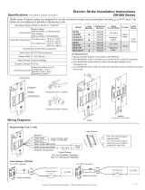
Wiring Diagrams
(Polarity Insensitive)
Blue:N.O.
GK450/480 series of electric strikes are designed for use with cylindrical and mortise locksets without deadbolt in hollow metal,
aluminum and wood jambs. The strikes can be configured to fail-safe or fail-secure on site.
Specifications
The strike is polarity insensitive
Electric Strike Installation Instructions
GK450/480 Series
Single Voltage (12V or 24V)
Power
input
N.C. for "Fail-Safe" Operation
Green:COM.
Yellow:N.C.
White:12VDC Red:24VDC
White:12VDC Red:24VDC
Latch monitor wires
Rated: 0.3A/6VDC
N.O. dry contact output:
opened status
N.C. dry contact output:
when the micro switch is
pressed by latch bolt.
Latch Monitor
GK450/480 Series
GK451/481 Series
(17mm
)
(
31.75mm)
1
1
/4
”
(
3
m
m
)
4 7/8” (123.8mm)
1
1
1
/
16”
(43.5mm)
(29.5mm
)
4
1”
8
/
(
50
1
m)m
3 3/8” (85.5mm)
/
3 1
4( ”4
m
m
5
)
1
3/
1
6”
1
1/1
6
”
1
/8”
(43.5mm
)
1
1
1/16”
7 15/16” (201.6mm)
1 7
/1
6”
”
6
1/1 7
)
mm0
81
(
3 1
/
4)
m
m5
4(
”
3 3/8” (85.5mm)
(17mm)
1
1
/
16
”
(
3mm)
1/
8
”
(
3
6.5mm)
Control Device
Faceplate
Mortise lockset
Deadlatch
Latchbolt
Keeper
Latch Monitor
Strike Body
For 24VDC Operation:
For 12VDC Operation:
Control Device
Control Device
Red
Black
White
Black
(Polarity Insensitive)
(Polarity Insensitive)
Dual Voltage (12V/24V)
12VDC or 24VDC or 12/24VDC
250mA/12VDC or 150mA/24VDC
Operating Voltage
Current Draw
1500 lbs (680Kg)
Operating Temperature
Humidity
Static Strength
Latch Throw
Keeper Width
GK450/451 series: 9/16" (15mm)
GK480/481 series: 3/4"(19mm)
1 3/4" (45mm)
0% to 85% Non-condensing
70 ft-lbs
Dynamic Strength
Destructive Attack: Level I
Line Security: Level I
Standby Power: Level I
Endurance: Level IV
Performance Level
For indoor use: + 14°F to + 120°F
(-10°C to +49°C)
300mA/12VDC, 150mA/24VDC
Single Voltage:
Dual Voltage:
GK450M-ST
GK451M-ST
GK480M-ST
GK481M-ST
Model
Latch
Construction
Frame
Latch
Zinc Alloy
Hollow
Metal
Wood
Hollow
Metal
Wood
9/16”
(15mm)
3/4”
(19mm)
Zinc Alloy
Zinc Alloy
Zinc Alloy
Stainless
Steel
Stainless
Steel
Stainless
Steel
N.O. for "Fail-Secure" Operation
Trim Plate
UL Requirements
- Wiring methods shall be in accordance with NFPA70.
- The GK450/480 Series is intended to be used with UL Listed Exit Hardware.
- The GK450/480 Series shall not impair the intended operation of an emergency exit.
- The GK450/480 Series shall not impair the operation of panic hardware mounted on the door.
Monitor
Throw
Body
Endurance
(Cycles)
100,000
100,000
100,000
100,000
100,000
100,000
250,000
250,000
250,000
250,000
250,000
250,000
250,000
250,000
100,000
100,000
GK450
GK450M
GK450-ST
GK451
GK451M
GK451-ST
GK480
GK480M
GK480-ST
GK481
GK481M
GK481-ST
For outdoor use: -31°F to +151°F
(-35°C to +66°C)

Installation Instructions
Install the mounting tabs
Drill the holes and cut the door frame
as indicated by the template
Connect to the power and test the
electric strike before finally mounting
the unit
Mark the position of the latch bolt on
the door frame as shown in figure
Align the installation template
to the marked line
Measure the vertical and horizontal position
of the latch bolt on the door leaf
Installing on Wood Frame and Hollow Metal Frame:
Copyright © All Rights Reserved. P-MU-GK450 Published: 2017.03.31
17mm
LP-050 LP-025
2"(50mm)
1" (25mm)
Please ensure that there is no back pressure on the keeper from the latch. As with most strike this may cause the strike
to bind and malfunction. It could also cause undo pressure on the solenoid and eventual failure of the strike.
Note
In case of over-cutting, use the enclosed trim
plate to cover up any errors.
*Factory default setting is Fail-Secure.
Using the Trim Plate
Optional Lip Extension Brackets
Fail-Secure / Fail-Safe Reversible
Place the wire inside the connector and use pliers
to press down on the head of the connector evenly.
Installing the Crimp Connectors
9/16” (123.8mm)
3 3/8” (85.5mm)
1 1/4”(31.75mm)
11/16” (17mm)
CL
CL
7 15/16” (201.6mm)
1 7/16” (36.5mm)
11
/16” (17mm)
CL
CL
3 3/8” (85.5mm)
2. Reverse the round screw.
3. Put back the round
screw and plug.
Fail-Secure
when " 2"
facing up
Fail-Safe when
"1" facing up
2
1
1. Remove the plug and
take out the round
screw.
/