Page is loading ...

Pg.1
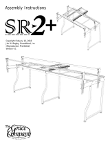
2ft. Extension Kit
Quilting Frame
Assembly Instructions
Table Of Contents
Parts List
Parts List . . . . . . . . . . . . . . . . . . . . . . . . . . . . . . . . . . . . . . . . . . . . . . . 2
Hardware . . . . . . . . . . . . . . . . . . . . . . . . . . . . . . . . . . . . . . . . . . . . . . . . 2
Assembly Steps
Step 1- Height Adjustable Leg Assembly . . . . . . . . . . . . . . . . . . . . . . . . . . 3
Step 2- Middle Legs Assembly. . . . . . . . . . . . . . . . . . . . . . . . . . . . . . . . . . 3
Step 3- Disassemble . . . . . . . . . . . . . . . . . . . . . . . . . . . . . . . . . . . . . . . . 3
Step 4- Middle Leg to Frame. . . . . . . . . . . . . . . . . . . . . . . . . . . . . . . . . . . 4
Step 5- Track and Shelf Supports . . . . . . . . . . . . . . . . . . . . . . . . . . . . . . . 5
Step 6- Table Support Assembly . . . . . . . . . . . . . . . . . . . . . . . . . . . . . . . . 5
Step 7- Front Top Track Support (FTTS) . . . . . . . . . . . . . . . . . . . . . . . . . . 6
Step 8- Table and Shelf Surface . . . . . . . . . . . . . . . . . . . . . . . . . . . . . . . . 7
Step 9- Front Top Track Support to Frame . . . . . . . . . . . . . . . . . . . . . . . . . 7
Step 10- Rail Assembly . . . . . . . . . . . . . . . . . . . . . . . . . . . . . . . . . . . . . . 8
Copyright August 2011
Jim M. Bagley, GraceWood, Inc
(Reproduction Prohibited)
Version 110826

Pg.2
M6 x 10mm Socket
Button Head Cap
Screw (SBHCS)
(36)
M6 x 10mm
Set Screw
(8)
4mm Allen
Wrench
(1)
3mm Allen
Wrench
(1)
13mm and 10mm
Open End Wrench
(1)
Hardware
Table Support (1)
2ft. Shelf Support (2)
2ft. Rail (4)
2ft. Table Surface (1)
Shelf Surface (2)
2ft. Front Top Track Support (FTTS) (2)
2ft. Back Track Support (2)
Rail Coupler (4)
Short Leg (2)
12ft. Track (4)
Parts List
Middle Track Brace (1)
Middle Lower Leg Brace (1)
2ft. Front Track Support (2)
Back Track Support
Coupler (1)
Front Track Support
Coupler (1)

Pg.3
Step 1: Height Adjustable Leg Assembly
Parts Needed:
2- Short Leg
Leveling
Foot
Height
Adjustable
Leg
1-1: Unscrew an M6 X 55mm SBHCS from a leg and slide a height
adjustable leg to the desired height. Then slide the SBHCS back into the
Height Adjustable Leg and out the other end. Slide a washer on the end
of the screw and tighten a nut onto the end of the screw. Follow this step
again for the other leg. Make sure all the legs are at the same height.
Fig. 1-1
M6 x 55mm
SBHCS
M6 Nylock Nut
7mm Washer
Step 2: Middle Legs Assembly
Parts Needed:
16- M6 x 10mm SBHCS
2- Short Leg
1- Middle Track Brace
1- Middle Lower Leg Brace
Note: Skip this step if setting up in crib.
Note: Do not completely tighten the screws in this step until all
the screws are installed for the Middle Leg Assembly.
2-1: Attach the Middle Lower Leg Brace to the Middle/Back Legs
with (8) M6 x 10mm SBHCS, as shown in Fig. 2-1. Make sure that
the side of the leg with no holes goes toward the inside.
2-2: Attach the Middle Track Brace to the Middle Legs with (8)
M6 x 10mm SBHCS.
Fig. 2-1
Middle Lower
Leg Brace
Short Leg
M6 x 10mm
SBHCS
Middle
Track Brace
No holes
Step 3: Disassemble
Parts Needed:
1- Quilting Frame
3-1: Remove (4) Rails from the Quilting Frame, taking
off (2) M6 X 16mm SBHCS and Ratchet Wheel Holder to
remove the Rail on the bottom of the Front Rail Bracket,
as shown in Fig. 3-1.
3-2: Pull off the Front Top Track Support (FTTS) by
removing the (8) M6 X 10mm SBHCS connecting it to the
Quilting Frame.
M6 x 10mm
SBHCS
M6 x 16mm
SBHCS
M6 x 10mm
SBHCS
M6 x 10mm
SBHCS
Ratchet Wheel
Holder
Fig. 3-1
FTTS

Pg.4
Fig. 3-2
3-3: Remove the Right Frame Corner by
taking out (3) M6 X 10mm SBHCS and (1) M6
X 25mm SBHCS.
3-4: Push down the side of the frame to
expose the back track and pull (2) Plastic
Tracks from the Back Track Support.
3-5: Remove (4) M6 X 10mm SBHCS from
the Front and Back Track Supports, as shown
in Fig. 3-2.
3-6: Take out (2) M6 X 10mm Set Screws
holding the Back Coupler.
3-7: Remove (4) M6 X 30mm SBHCS from
the left Shelf Supports.
3-8: Pull off the left half of the quilting
frame.
Step 4: Middle Leg to Frame
Parts Needed:
4- M6 x 10mm SBHCS
4- M6 x 30mm SBHCS
2- M6 X 10mm Set Screw
1- Back Track Support Coupler
1- Middle Leg Assembly
4-1: Attach the front side of the Track Supports
on the left half of the frame to the inside holes
on the front side of the Middle Leg with (2) M6 x
10mm SBHCS, as shown in Fig 4-1.
4-2: Attach the other side of the Back Track
Support to the inside holes on the Middle Leg with
(2) M6 x 10mm SBHCS.
4-3: Attach the (2) Shelf Supports on the left
half of the frame to the Middle Leg with (4) M6 X
30mm SBHCS.
4-4: Place the Back Track Support Coupler
into Back Track Support so half of the coupler
is hanging out and lock in place using (2) M6 X
10mm Set Screws.
M6 x 30mm
SBHCS
M6 x 10mm
SBHCS
Fig. 4-1
M6 x 10mm
SBHCS
M6 x 10mm
Set Screw
M6 X 30mm
SBHCS
M6 x 10mm
Set Screws
Back Coupler
Back Coupler

Pg.5
Step 5: Track and Shelf Supports
Parts Needed:
16- M6 x 10mm SBHCS
1- 2ft. Front Track Support
1- 2ft. Back Track Support
2- 2ft. Shelf Support
5-1: Place both sides of your frame
about 2 feet apart. Attach 2ft. Front
and Back Track Supports to both
Middle Leg Stands with (8) M6 X
10mm SBHCS, as shown in Fig. 5-1.
Note: Don’t tighten the screws until
both sides of the 2ft. Track Supports
are attached to the Middle Legs. Make
sure the Track Supports sit ush on the Middle Legs.
6-2: Take (2) 2ft. Shelf Support and attach them to the Middle Legs using (8) M6 X 10mm SBHCS,
as shown in Fig. 5-1.
Step 6: Table Support Assembly
Parts Needed:
2- 6 x 10mm SBHCS
1- Table Support
6-1: Attach (1) Table Support to the
middle of the 2ft. Track Supports using (2)
M6 x 10mm SBHCS, as shown in Fig. 6-1.
Fig. 5-1
Fig. 6-1
M6 x 10mm
SBHCS
2ft. Shelf
Support
2ft. Back
Track Support
M6 x 10mm
SBHCS
Table Support
2ft. Front
Track Support

Pg.6
Fig. 7-2
Fig. 7-3
M6 x 10mm
Set Screw
Track Runner
12ft. Long
Plastic Track
Step 7: Front Top Track Support (FTTS)
Parts Needed:
4- M6 X 10mm Set Screw
3- M6 X 10mm SBHCS
1- M6 X 25mm SBHCS
1- 2ft. Track Runner
1- Track Coupler
4- 12ft. Plastic Track
1- Front Top Track Support (FTTS)
7-1: Push down the right side of the frame to expose the
Back Track Support and slide (2) 12ft. Plastic Tracks into
Back Track Support, as shown in Fig. 7-1.
7-2: Replace Right Frame Corner, putting (3) M6 X 10mm
SBHCS and (1) M6 X 30mm back from where they were
removed.
7-3: Pull FTTS apart, by taking out (2) M6 X 10mm Set Screws
from the left FTTS. Pull the left FTTS off the Track Coupler, leave the Coupler
attached to the right FTTS.
7-4: Slide the Track Coupler, from the extension kit, so it is half way in the 2ft. FTTS.
7-5: Thread (2) M6 X 10mm Set Screw into the rst two holes on the 2ft. FTTS, to tighten the
Coupler in place, as shown in Fig 7-2.
7-6: Slide the Left FTTS onto Coupler, in the 2ft. FTTS. Then on the other side of the 2ft. FTTS slide
on the Coupler in the Right FTTS, as shown in Fig 7-2.
7-7: Thread in (2) M6 X 10mm Set Screw into the inside holes on each FTTS, as shown in
Fig. 7-2.
Note: The screws locking the Couplers in place will not thread in all the way.
7-8: Slide (2) 12ft. Plastic Tracks into the FTTSs, as shown in Fig. 7-3.
M6 x 10mm
SBHCS
M6 X 25mm
SBHCS
Fig. 7-1
Push Down
Here

Pg.7
Fig. 9-1
Fig. 8-1
Step 9: Front Top Track Support
Parts Needed:
10- M6 x 10mm SBHCS
2- Front Top Track Support
(FTTS)
9-1: Place a FTTS on the Front Track
Support, line up the holes on Track
Support with the holes on the FTTS,
as shown in Fig. 9-1.
9-2: Thread (10) M6 X 10mm SBHCS
down through the FTTS and Track
Support, making sure not to fully tighten.
9-3: Replace the Carriage onto the frame.
Use Carriage to align FTTS Assembly and
tighten down M6 X 10mm SBHCS once tracks are aligned.
Step 8: Table and Shelf Surface
Parts Needed:
1- 2ft. Table Surface
1- 2ft. Shelf Surface
8-1: Lay the plastic table approximately
centered, with the textured surface
side UP on the Table Supports as shown
in Fig. 8-1.
8-2: Attach the Shelf Table, with the textured surface side UP to the Shelf Supports with the
pre-installed double sided tape, as shown in Fig. 8-1.
2ft. Table
Surface
2ft. Shelf
Surface
M6 x 10mm
SBHCS
Front Top Track Support
(FTTS)

Pg.8
Congratulations! Assembly of your 12 Foot Quilting Frame is now complete.
• For questions on installing your fabric or for further questions, on assembly, of your quilting
frame, please refer to your Quilting Frame instruction booklet.
• For any further questions please contact your dealer or The Grace Company directly at
1-800-264-0644 or info@graceframe.com.
Fig. 10-1
Fig. 10-2
Step 10: Rail Assembly
Parts Needed:
4- Rail Coupler
4- 2ft. Rail
4- Rail Assembly
10-1: Pull Rail Assembly apart by removing (2) M6 X 20mm Set Screws from left side of Rail
Assembly, as shown in Fig. 10-1.
10-2: Slide a Rail Coupler half way into the left 5ft. Rail, locking it in place using (2) M6 X 20mm Set
Screws.
10-3: Slide both of the 5ft. Rails with coupler onto each side of a 2ft. rail, as shown in Fig. 10-2, and
put (4) M6 X 20mm Set Screws in to nish Rail Assembly.
10-4: Repeat Steps 10-1 through 10-3 for remaining Rails.
10-5: Place sewing machine in place on the frame and insert the Take Up Rail through the throat of
the sewing machine and into the ratchet housings.
10-6: Take one of the Rails with Ratchet Wheels
and slide it up into the Front Rail Mount End until it
clicks into place. Then place the ratchet wheel holder
in between the Ratchet Wheel and Rail End as shown
in Fig. 10-3.
10-7: Screw (2) of the M6 x 16mm SBHCS into the
Ratchet Wheel Holder. Follow the same step for the
other side of the Rail.
10-8: Replace remaining (2) Rail Assemblies.
2ft. Rail
Rail Coupler
M6 X 20mm
Set Screw
M6 x 20mm
Set Screw
M6 x 16mm
SBHCS
Ratchet Wheel
Holder
Fig. 10-3
M6 Hex Nut
(Pre-installed)
/