Page is loading ...

Coronet Frame Assembly Instrucons | 1
Baby Lock Coronet Frame
Assembly Instrucons
Table of Contents
Frame Parts and Hardware 2
Table and Leg Assembly 5
Side Arm and Pole Assembly 8
Introducon
The Coronet Frame can be set up to work with either the Coronet™ (a 16-inch quilng machine) or
the Crown Jewel® (an 18-inch quilng machine). The frame enables you to use either stand-up quilng
machine within a smaller footprint than our other Frames, yet you can do quilts of any size.
What’s Included
Your Coronet Frame is delivered in two separate boxes. Aer opening, check immediately to see that you
have received the items listed in the Parts and Hardware list found on pages 2 and 3.
Box 1:
Includes side arms and supports, upper leg supports, Coronet Frame assembly instrucons, and all other
parts and hardware.
Box 2:
1 – Table top with tracks
2 – Lower legs
1 – Front pole (56”)
1 – Rear pole (68”)
NOTES:
1.
REVISIONS
ECO
REV.
DESCRIPTION
DATE
APPROVED
A
INITIAL RELEASE
BILL OF MATERIALS ENG-10007
ITEM
PART NUMBER
DESCRIPTION
QTY.
1
QF05300-300
TABLE ASSY, TACONY FRAME
1
2
QF05300-402
CORNER HEIGHT BAR, A
2
3
QF05300-403
CORNER HEIGHT BAR, B
2
4
QF05300-401
END LEG STAND
2
5
QF09318-303
SCREW-M6x12 SWH
6
6
QF09318-07
Screw-M8x16 SBHCS
16
7
QF09318-108
LEVELING GLIDE
4
8
ENG-10005
ASSY-SIDE ARM RIGHT LF
1
9
ENG-10006
ASSY-SIDE ARM LEFT LF
1
10
QF10005
POLE FRONT LF
1
11
QF10009
POLE REAR LF
1
12
QF10011
END CAP-REAR POLE LF
2
ENG-10007
D
C
B
A
A
B
C
D
1
2
3
4
5
6
7
8
8
7
6
5
4
3
2
1
THE INFORMATION CONTAINED IN THIS
DRAWING IS THE SOLE PROPERTY OF
Handi Quilter. ANY REPRODUCTION IN
PART OR AS A WHOLE WITHOUT THE
WRITTEN PERMISSION OF
Handi Quilter IS PROHIBITED.
PROPRIETARY AND CONFIDENTIAL
NEXT ASSY
USED ON
APPLICATION
DIMENSIONS ARE IN INCHES
TOLERANCES:
FRACTIONAL
ANGULAR: MACH
1
BEND
TWO PLACE DECIMAL
0.01
THREE PLACE DECIMAL
0.005
INTERPRET GEOMETRIC
TOLERANCING PER:
MATERIAL
FINISH
DRAWN
CHECKED
ENG APPR.
MFG APPR.
Q.A.
DATE
NAME
Handi Quilter
SIZE
B
DWG. NO
REV
SHEET 1 OF 1
WEIGHT:
SCALE: 1:16
UNLESS OTHERWISE SPECIFIED:
A
LBS
Sheet Name: Sheet1
Filename
FRAME-LITTLE FOOT
Baby Lock Consumer Helpline: 800-313-4110
www.babylock.com
Back of
Frame
Front of
Frame

2 | www.babylock.com
Frame Parts and Hardware
1 – Table top with tracks
(#QF05300-300, Box 2)
1 – Front pole (56")
(#QF10005, Box 2)
1 – Rear pole (68")
(#QF10009, Box 2)
M6 x 10mm socket cap screw
End Caps
2 – Rear pole endcaps
(#QF10011, Box 1)
2 – Upper leg A
(#QF10017, Box 1)
2 – Upper leg B
(#QF10016, Box 1)
2 – Lower legs
(#QF05300-401, Box 2)
QF09318-103
BUNGEE HOLDER
BUNGEE HOLDER COVER
QF09318-104
BUNGEE HOLDER SPACER
QF09318-103
RATCHET STOP
QF09318-203
RATCHET STOP HOLDER
QF09318-205
RATCHET STOP BUSHING
QF09318-201
CONNECTOR BOLT
QF09318-204
QF09318-202
RATCHET STOP MOUNT
RAIL BEARING SNAP
QF09318-105
RAIL BEARING SNAP COVER
QF09318-106
Fig. 10-2
QF09318-105
QF09318-703
OUTSIDE POLE END
V-GROOVE BEARING
QF09318-705
QF09318-713
HAND WHEEL COLLAR
QF09318-714
STEEL SNAPPING BUTTON/LOCKING CLIP
LEVELING FOOT
4 – Leveling foot
(#QF09318-108, Box 1)
4 – Nylon washers
(#QF05300-157, Box 1)
M6 x 10mm socket cap screw
End Caps
14 – M6 x 10mm socket
cap screws
(#QF10006, Box 1)
20 – M8 x 20mm socket
buon head cap screws
(SBHCS)
(#QF10959, Box 1)
Right Side arm
Left Side arm
Left Side pole clamp
Right Side pole clamp
Side Arm Pole
Corner Connector
L-Bracket
1 – Right side arm
(#QF10007, Box 1)
Right Side arm
Left Side arm
Left Side pole clamp
Right Side pole clamp
Side Arm Pole
Corner Connector
L-Bracket
1 – Le side arm
(#QF10008, Box 1)

Coronet Frame Assembly Instrucons | 3
Right Side arm
Left Side arm
Left Side pole clamp
Right Side pole clamp
Side Arm Pole
Corner Connector
L-Bracket
2 – Front pole corner
connectors
(#QF10003, Box 1)
Right Side arm
Left Side arm
Left Side pole clamp
Right Side pole clamp
Side Arm Pole
Corner Connector
L-Bracket
4 – L-brackets
(#QF10010, Box 1)
Right Side arm
Left Side arm
Left Side pole clamp
Right Side pole clamp
Side Arm Pole
Corner Connector
L-Bracket
2 – Side arm pole
(#QF10004, Box 1)
Right Side arm
Left Side arm
Left Side pole clamp
Right Side pole clamp
Side Arm Pole
Corner Connector
L-Bracket
1 – Right side arm
pole clamp (for part
codes, see right)
(Box 1)
#QF10041 #QF10042
Right Side arm
Left Side arm
Left Side pole clamp
Right Side pole clamp
Side Arm Pole
Corner Connector
L-Bracket
1 – Le side arm
pole clamp (for part
codes, see right)
(Box 1)
#QF10041 #QF10043
1 – 17/13 mm wrench
(for leveling feet)
(#QF09318-114, Box 1)
HAND WHEEL ASSY
QF09318-720
SHORT BOLT RATCHET WHEEL
QF09318-730
QF09318-730
LONG BOLT RATCHET WHEEL
1 – 5 mm hex tool
(QF09318-113, Box 1)
HAND WHEEL ASSY
QF09318-720
SHORT BOLT RATCHET WHEEL
QF09318-730
QF09318-730
LONG BOLT RATCHET WHEEL
1 – 4 mm hex tool
(QF09318-112, Box 1)
6 – Easy-Grasp
Quilt Clamps
(#BLQ-EQC, Box 1)

4 | www.babylock.com
1 – Deluxe Quilt Clamp
(#BLQ-DQC, Box 1)
3 – 2-Inch Small Quilt
Clamps
(#BLQ-SQC, Box 1)
3 – 3-Inch Large Quilt
Clamps
(#BLQ-LQC, Box 1)

Coronet Frame Assembly Instrucons | 5
Table and Leg Assembly
Parts Needed
1 - Table top secon
2 - Upper leg A
2 - Upper leg B
2 - Lower legs
4 - Leveling feet
20 - M8 x 20 mm socket buon
head cap screws
4 - Nylon washers
2 - L-brackets
Tools Required
5 mm hex tool (provided)
17/13 mm wrench (provided)
Spirit level (not provided)
1. Place the table top secon face
down onto a protecve surface.
2. Aach the upper legs: Posion the
upper legs A and B so the height
adjustment holes face each other
across the short end of the table.
3. Aach each upper leg to the table
with four (4) M8 x 20 mm socket
buon head cap screws (SBHCS)
through the upper corner leg
brackets into the holes on the
sides of the table.
Height
adjustment
holes

6 | www.babylock.com
4. Tighten with the 5 mm hex tool. (Do not fully ghten the screws at this me as you will remove these
screws to aach L-brackets later in the installaon process.)
5. Insert the lower legs: Slide one
lower leg onto the two upper
corner legs on each end of the
frame. The extended end of the
lower leg faces what will be the
front of the frame. Repeat for
the opposite end of the frame,
orienng the extended end of
the lower leg the same way as
the rst leg.
6. Insert the leveling feet: Thread a
leveling foot into each end of the
leg assemblies.
7. Use the 17/13 mm wrench to
ghten the leveling foot, leaving
about 1/2 inch of threads exposed
to make it easier to level the
frame later.
Back of
Frame
Front of
Frame
Front of
Frame
Back of
Frame

Coronet Frame Assembly Instrucons | 7
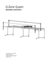
8. Set the frame height: Decide on
the preferred height of the frame.
Use the image at the right to
idenfy which height adjustment
holes to use for securing the
lower legs.
Place an M8 x 20mm SBHCS with a
nylon washer into the same height
seng on each of the corner
legs. (The nylon washer protects
the paint in case you change the
height seng later.) Fully ghten
the screw on each leg with the
5 mm hex tool.
NOTE: Adjust the frame height
so that when standing at the
front of the machine with your
hands on the front handle
bars, your elbows are bent at a
90-degree angle.
33” - 34” FLOOR TO QUILT PLANE
34” - 36” FLOOR TO QUILT PLANE
36” - 38” FLOOR TO QUILT PLANE
38” - 40” FLOOR TO QUILT PLANE
41” - 42” FLOOR TO QUILT PLANE
42” - 44” FLOOR TO QUILT PLANE
9. Stand the frame upright: With the
help of a second person, li the
frame into an upright posion.
10. Aach L-brackets: With the 5 mm
hex tool, loosen and then remove
the screws from the front of an
upper leg. (See the detail in the
next gure.)
Front of
Frame
Front of
Frame

8 | www.babylock.com
11. Align the holes in one of the
L-brackets over the leg holes on
the long side of the table, replace
the screws, and ghten. Repeat
steps 10 and 11 with the front of
the other upper leg.
Side Arm and Pole Assembly
Parts Needed
2 – Side arms
14 – M6 x 10mm socket cap screws
2 – L-brackets
1 – Le side arm pole clamp
1 – Right side arm pole clamp
2 – Side arm poles
2 – Front pole corner connectors
2 – Rear pole endcaps
1 – Rear pole
1 – Front pole
Tools Required
5 mm hex tool (provided)
4 mm hex tool (provided)
17/13 mm wrench (provided)
1. Aach the right and le side arms:
Use the 5 mm hex tool to remove
the M8 x 20mm socket buon
head screws (2) from the sides of
the le and right upper legs, one
side at a me. Using the boom
row of holes on each side arm,
place a screw in the far le hole
in the le side arm and align with
the far le hole in the upper leg.
Tighten the screws to secure to
the side of the frame.
NOTE: Note the orientaon of the side arms in the gure
above. The vercal metal extension is posioned toward
the back of the frame.
M6 X 10mm
SCREW
M8 X 20mm
SCREWS

Coronet Frame Assembly Instrucons | 9
2. Use the 4 mm hex tool to screw
one of the M6 x 10mm socket cap
screws to secure the side arm to
the L-bracket on table-top frame.
NOTE: If the L-bracket isn’t ush with the side arm, you will need to loosen the screws that hold it
to the front of the table and slide it unl it is against the side arm. Then reghten the screws and
secure the side arm to the L-bracket as described in step 2.
3. Repeat steps 1 and 2 for the right side arm. If necessary, fully ghten the screws connecng the side
arms to the frame.
4. Aach the le and right side arm
pole clamps: Use the 4 mm hex
tool and two (2) M6 x 10mm
socket cap screws to aach the
side arm pole clamps to each
side arm.
PUSH BUTTON
NOTE: Make sure you have idened the right and le side arm pole clamps. When properly
installed, the silver push buon on the side arm pole clamp will face the center of the frame.
M6 X 10mm
SCREW
M8 X 20mm
SCREWS

10 | www.babylock.com
5. Press in the push buon on the
side arm pole clamp and slide it
onto the side arm pole bracket.
18-inch machines:
If you are seng up the Coronet
Frame for an 18-inch machine,
slide on the Side Arm Poles so
that the buon snaps into the rst
hole (see arrow).
16-inch machines:
If you are seng up the Coronet
Frame for a 16-inch machine,
make sure the buon snaps into
the second hole
(see arrow).
Repeat with the other side
of the frame.
Set up for a 16-inch machine
6. Assemble the front pole: Idenfy
the front pole corner connectors.
Press in the buon on one of
the front pole corner connectors
and insert it into the le side of
the front pole unl the buon
snaps in place. Press in the buon
on the other front pole corner
connector and insert it into the
right side of the front pole unl
the buon snaps in place.
C
Set up for an 18-inch machine

Coronet Frame Assembly Instrucons | 11
7. Aach the front pole assembly
to the frame: Press in the buon
on the le side of the front pole
assembly and insert the pole
into the side arm poles unl the
buon snaps in place. Repeat with
the right side of the front pole
assembly and the right side of
the frame.
8. Aach the other L-brackets: Insert two (2) M6 x 10mm socket cap screws into the holes on the inside
of the side arm and use the 4 mm hex tool to ghten the screws to secure side arm to the L-bracket.
Insert two (2) M6 x 10mm socket cap screws into the holes on the inside of the front pole corner
connector and use the 4 mm hex tool to ghten the screws to secure the front pole corner connector
to the L-bracket. Repeat on the other side of the frame.
Set up for an 18-inch machine:
If you are seng up the frame
for an 18-inch machine, align the
holes in the L-bracket with the
side arm holes as shown in the
gure at the right (front two holes
on the side arm).
G
Set up for an 18-inch machine.

12 | www.babylock.com
Set up for 16-inch machine:
If you are seng up the frame
for a 16-inch machine, align the
holes in the L-bracket with the
side arm holes as shown in the
gure at the right (back two
holes on the side arm).
G
Set up for a 16-inch machine
9. Assemble and aach the rear
pole: Insert a rear pole endcap
into each end of the rear pole.
Aach the rear pole to the side
arm clamps. Open the clamps by
loosening the knob on the back.
Then snap in the pole and ghten
the knobs as needed.
C
NOTE: When you put the carriage and quilng machine onto the frame, you will need to remove
the rear pole temporarily and then replace the pole, placing it through the throat space of
the machine.

Coronet Frame Assembly Instrucons | 13
10. Tighten the tracks: Place the
machine carriage on the tracks
with the encoder toward the back
of the frame. Slide the carriage on
the tracks from side to side to ne
tune the track posion. To fully
fasten the tracks to the table top,
use the 4 mm hex tool to ghten
the six (6) installed M6 x 10 mm
socket cap screws.
Access the three screws on each track from below the table top:
one at the le, one in the center, and one at the right
(circled above).
NOTE: If the tracks are ght up against the table top, you might need to use the 4 mm hex tool to
rst loosen the three (3) installed M6 x 10 mm socket cap screws on the track supports: one at the
le, one in the center, and one at the right.
11. Level the frame: Using a spirit level, check and adjust the frame top to be level in the place where
it will be used, both front to back and side to side, by adjusng the leveling feet. If no spirit level is
available, check the table with the machine on the carriage and the tracks. When the table is level,
the machine should stay where you put it and not roll forward, backward, or side to side.
12. Double check the frame height: Adjust the frame height so that when standing at the front of the
machine with your hands on the front handle bars, your elbows are bent at a 90-degree angle. Refer
back to step six under Table and Leg Assembly. Remove the machine and carriage from the frame.
Then have a helper li the frame weight o the height adjusng screws so you can make a height
adjustment to both sides of the frame.

14 | www.babylock.com
/