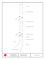
Grace Company Majestic Frame Operating instructions

Type
Operating instructions

This manual is also suitable for

Grace Company Majestic Frame is a professional-grade quilting frame that provides a sturdy and adjustable platform for quilters of all skill levels. With its versatile design, the frame can be assembled in two size options: king (10 ft) or crib (5 ft), making it suitable for projects of various sizes. The frame's height can be adjusted to accommodate different user preferences, and its sturdy construction ensures stability during quilting.

Grace Company Majestic Frame is a professional-grade quilting frame that provides a sturdy and adjustable platform for quilters of all skill levels. With its versatile design, the frame can be assembled in two size options: king (10 ft) or crib (5 ft), making it suitable for projects of various sizes. The frame's height can be adjusted to accommodate different user preferences, and its sturdy construction ensures stability during quilting.

Majestic
Professional Series Quilting Frame
Assembly Instructions
Copyright March 2010
Jim M. Bagley, GraceWood, Inc
(Reproduction Prohibited)
Print Date 03-11-10
Table of Contents
Frame Assembly
Before You Begin...................................................................................................2
Box 1
Parts list................................................................................................................2
Tools ....................................................................................................................3
Hardware List........................................................................................................4
Plastic Parts List.....................................................................................................5
Box 2
Parts list................................................................................................................5
Assembly Steps
Step 1 - Height adjustable Leg Assembly.................................................................6
Step 2 - Side Leg Assembly....................................................................................6
Step 3 - Middle leg Assembly..................................................................................7
Step 4 - Track Support Assembly.............................................................................7
Step 5 - Table support Assembly.............................................................................8
Step 6 - Frame End Assembly.................................................................................8
Step 7 - Take Up Rail End Assembly........................................................................9
Step 8 - Front Rail End Assembly............................................................................9
Step 9 - Bungee Hold Plate Assembly.....................................................................10
Step 10-Rail Assembly...........................................................................................11
Step 11-Track Runner Assembly..............................................................................12
Step 12-Table Assembly.........................................................................................14
Step 13-Rail To Frame Assembly.............................................................................14
Fabric Installation
Step 1- Batting......................................................................................................16
Step 2- Quilt Top to Quilt Top Rail...........................................................................17
Step 3- Quilt Backing to Backing Rail.......................................................................17
Step 4- Attaching Quilt Layers to Take Up Rail..........................................................17
Rolling your Fabric.................................................................................................18
Turning your Quilt Around......................................................................................18
Making Cloth Leaders.............................................................................................19
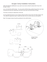
Bungee Clamp Instructions.....................................................................................19
Sewing Tips...........................................................................................................20
Warranty Information
for your Grace Machine Quilting Frame
The Machine Quilting Frame has a One-Year limited warranty on all parts. The Grace Company will
repair or replace, at its discretion, any part with problems due to our manufacturing, or defects in
materials. This warranty does not cover parts damaged through misuse, improper storage, improper
assembly, loss, natural events, and willful destruction. Parts must be returned to the Grace Company,
shipping prepaid, before we can repair or replace them. We will promptly return the repaired/
replaced part at our expense if done within a year of the purchase date. After one year customers
are responsible for the cost of return shipping.
Pg. 2
Welcome!
Before you begin assembly of your new home machine quilting system, keep in mind the following:
1: Assembly of your new quilt frame will be simple and step by step.
2: Read through each step completely before beginning the step.
3: When beginning assembly of your frame we recommend you assemble it in the room you
aregoingtobequiltinginbecauseitislargeandcouldbedifculttomove.
4: Your new quilt frame can be assembled in two size options, king which is 10 ft. or crib
at 5 ft.
5: Using the parts list as a reference, take the parts out of the boxes and make sure that you
have all the needed parts
6: Identify hardware packets: All hardware is separated by type and each packet is labeled for
easeinidentication.
7: If anything appears to be missing or damaged please contact your dealer or the Grace
Company directly at 1-800-264-0644 or info@graceframe.com.
Lower Leg Brace(4)
Side Leg Brace Right(1) Side Leg Brace Left(1)
Frame End Left(1) Frame End Right(1)
Table Support(6)
Take Up Rail End
Right(1)
Front Rail End
Left(1)
Track Runner
Coupling(2)
Take Up Rail
End Left(1)
Front Rail End
Right(1)
Box 1
Parts List
Plastic Tubing(4)
Short Plastic Track(4) (pre-installed in two track runners)
Track Runner(4)
Table(2)
Long Plastic Track(4)
Track Support(4)
Hardware Parts List
***Drawings display hardware in actual size***
Pole List
(3) 57-11/16" Aluminum Pole
(3) 36" Aluminum Pole
(3) 105" Fabrifast Tubing
(8) 5/16 X 2"
Carriage Bolt
(4) 5/16 X 1-1/2"
Hex Bolt
(2) 1/4" X 45mm
Connector Bolt
(4) 1/4" X 60mm
Connector Bolt
(4) 5/16 Plastic
Knob
(3) 1/4 X 1-1/2"
Truss Bolt
(4) 1-1/4"
Fender Washer
(8) 5/16" Flat
Washer
(8) 1/4" Flat
Washer
(6) 1/4"
Rectangle Nut
(8) 5/16" Jamb
Nut
(4) 5/16"
Nylock Nut
(8) Plastic
Roller
(1) 4mm Allen
Wrench
(3) 14" Aluminum Pole
(18) 10-24 Socket
Head Screw
(6) Aluminum
Rail Coupler
(1) Fabrifast
Tool
(6) #10 Square
Nut
(1) 3mm Allen
Wrench
Open End Wrench
10mm X 13mm(1)
Tools
(Provided)
M4 Allen
Wrench(1)
M5 Allen
Wrench(1)
Fabri-Fast Tool(1)
Bungee Clamp(4)
(2) M6 X 35mm (SHBC) Socket
Button Head Cap Screw
(4) M6 X 35mm Hex Bolt
(2) M6 Hex Nut
(24) M5 X 16mm (SHBC)
Socket Button Head Cap Screw
(66) M6 X 10mm (SHBC) Socket
Button Head Cap Screw
(4) M6 X 12mm (SHBC) Socket
Button Head Cap Screw
(50) M5 X 10mm (SHBC) Socket
Button Head Cap Screw
(2) M6 X 20mm Hex Bolt
(12) M5 X 10 (SCH) Socket
Countersunk Head Screw
(4) M6 Nylock
Nut
Pg. 3
Hardware Parts List
***Drawings display hardware in actual size***
Pole List
(3) 57-11/16" Aluminum Pole
(3) 36" Aluminum Pole
(3) 105" Fabrifast Tubing
(8) 5/16 X 2"
Carriage Bolt
(4) 5/16 X 1-1/2"
Hex Bolt
(2) 1/4" X 45mm
Connector Bolt
(4) 1/4" X 60mm
Connector Bolt
(4) 5/16 Plastic
Knob
(3) 1/4 X 1-1/2"
Truss Bolt
(4) 1-1/4"
Fender Washer
(8) 5/16" Flat
Washer
(8) 1/4" Flat
Washer
(6) 1/4"
Rectangle Nut
(8) 5/16" Jamb
Nut
(4) 5/16"
Nylock Nut
(8) Plastic
Roller
(1) 4mm Allen
Wrench
(3) 14" Aluminum Pole
(18) 10-24 Socket
Head Screw
(6) Aluminum
Rail Coupler
(1) Fabrifast
Tool
(6) #10 Square
Nut
(1) 3mm Allen
Wrench
M6 Allen
Wrench(1)
Backing Tape(16)
Hardware Parts List
***Drawings display hardware in actual size***
Pole List
(3) 57-11/16" Aluminum Pole
(3) 36" Aluminum Pole
(3) 105" Fabrifast Tubing
(8) 5/16 X 2"
Carriage Bolt
(4) 5/16 X 1-1/2"
Hex Bolt
(2) 1/4" X 45mm
Connector Bolt
(4) 1/4" X 60mm
Connector Bolt
(4) 5/16 Plastic
Knob
(3) 1/4 X 1-1/2"
Truss Bolt
(4) 1-1/4"
Fender Washer
(8) 5/16" Flat
Washer
(8) 1/4" Flat
Washer
(6) 1/4"
Rectangle Nut
(8) 5/16" Jamb
Nut
(4) 5/16"
Nylock Nut
(8) Plastic
Roller
(1) 4mm Allen
Wrench
(3) 14" Aluminum Pole
(18) 10-24 Socket
Head Screw
(6) Aluminum
Rail Coupler
(1) Fabrifast
Tool
(6) #10 Square
Nut
(1) 3mm Allen
Wrench
M3 Allen
Wrench(1)
Box 1
Parts List (Continued)
Pg. 4
Hardware List
M6 X 10mm
Socket Head
Screw(66)
M5 X 10mm
Socket Head
Screw(50)
M8 X 20mm
Carriage Bolt(4)
M8 X 15mm
Carriage Bolt(4)
M6 X 30mm
Hex Bolt(2)
M6 X 15mm
Hex Bolt(10)
M6 Nylock Nut(2)
M5 Washer(22)
M8 Plastic Knob(8)
M6 Plastic Knob (10)
38mm Rail(8)
Box 2
38mm Rail Coupler(4)
Leg Assembly(6)
Leg Table Brace(4)
Plastic Parts List
Fourth Rail End
Cap(2)
(pre-assembled)
Hand Wheel(1)
(pre-assembled)
Left Corner(1)
Right Corner(1)
Ratchet Rail insert
Assembly(5)
(pre-assembled)
Ratchet Rail insert
Assembly for
Hand wheel(1)
(pre-assembled)
Front Rail End
Mount(2)
Take Up Rail Mount(2)
Pg. 5
Bungee Hold Plate(2) Bungee Bar(4)
Parts List
Side Leg
Brace Right
Height
Adjustable
Leg
Leveling Foot
Step 1: Height Adjustable Leg-Assembly
Parts Needed:
6- Leg Assembly
Fig. 1-1
1-1: To adjust the height of the leg, unscrew the pre-assembled M8 Socket Head Screws on
each side, and slide the leg to the desired height. Reinsert the screws into the leg on each side,
as shown in Fig. 1-1 and tightly thread back in. Repeat this step again for the other legs, making
sure the screws in all the legs are at the same position.
Note: As a general recommendation, most users from 5’4” to 5’6” tall prefer the legs positioned
with the screws in the center hole. Preferred heights may vary.
M8 X 16mm Socket
Head Screw
Leg Assembly
Step 2: Side Stand-Assembly
Parts Needed:
24-M6 X 10mm Socket Head Screw
1-Side Leg Brace Left
1-Side Leg Brace Right
2-Lower Leg Brace
2-Leg Table Brace
4-Leg Assembly
M6 X 10mm Socket
Head Screw
2-1: Attach the Leg Table Brace to the
top two the leg assemblies with (4) M6
X 10mm Socket Head Screws. Do not
tighten any screws completely until all the
braces are in place.
2-2: Attach the Lower Leg Brace on the
same side as the Leg Table Brace with (4)
M6 X 10mm Socket Head Screws.
2-3: On the opposite side, attach the Side
Leg Brace Right to the Leg Assemblies
with (4) M6 X 10mm Socket Head Screws,
as shown in Fig. 2-1. Tighten down all
screws completely now.
2-4: Repeat Steps 2-1 through 2-3 to
assemble the Left Side Stand Assembly.
Leg Table Brace
Leg Assembly
Lower Leg Brace
Fig. 2-1
Pg. 6
M6 X 10mm Socket
Head Screw
Note: Skip to Step 4 if setting up in crib size.
3-1: Attach the Leg Table Brace to the top of the leg
assemblies with (4) M6 X 10mm Socket Head Screws.
Do not tighten any screws completely until all braces
are attached.
3-2: Attach the Lower Leg Brace with (4) M6 X 10mm
Socket Head Screws.
3-3: Repeat the previous two steps for the other side,
as shown in Fig. 3-1. When all braces are in place,
tighten down all screws completely.
Step 3: Middle Stand-Assembly
Parts Needed:
16-M6 X 10mm Socket Head Screw
2-Lower Leg Brace
2-Leg Table Brace
2-Leg Assembly
Fig. 3-1
M6 X 10mm Socket
Head Screw
Step 4: Track Support-Assembly
Parts Needed:
16-M6 X 10mm Socket Head Screw**
4-Track Support**
1-Middle Leg Assembly*
1-Right Leg Assembly
1-Left Leg Assembly
* King size only
**For crib size only (2) Track Supports and (8)
Socket Head Screws are needed.
Note: For Crib assembly, ignore steps 4-2
and 4-4 because you will not have the Middle
Leg Stand. Instead, attach Track Supports
from one Side Leg Stand to the other Side Leg
Stand, as shown in Fig. 4-3.
4-1: Attach a Track Support to the Left Leg
Stand with (2) M6 X 10mm Socket Head Screw,
as shown in Fig. 4-1.
Note: Make sure Track Supports line up with the
outside holes on the right and left leg stands, as shown in
Fig. 4-2. Don’t tighten screws completely until all Track Supports
are attached to Leg Assemblies.
Leg Table Brace
M6 X 10mm Socket
Head Screw
Lower Leg
Brace
Fig. 4-1
Track Support
Fig 4-2
Pg. 7
(King assembly only)
Pg. 8
4-2: Attach the other end of the track support to the
Middle Leg Stand with (2) M6 X 10mm Socket Head
Screws.
4-3: Attach another Track Support to the Right Leg
Stand, with (2) M6 X 10mm Socket Head Screws.
4-4: Attach the other end of this track support to the
Middle Leg Stand with (2) M6 X 10mm Socket Head
Screws.
4-4: Follow steps 4-1 through 4-4 again, for the
other side of the frame. Tighten all screws completely
after completing this step.
Step 5: Table Supports-Assembly
Parts Needed:
24-M5 X 10mm Socket Head Screw**
6-Table Supports**
**Only 12 Socket Head Screws and 3 Table
Supports needed for crib size.
5-1: Attach a Table Support to Track Supports using
(2) M5 X 10mm Socket Head Screws on each side, as
shown in Fig. 5-1.
5-2: Repeat this process to install the other 5 Table
Supports. (Or the other 2 Table Supports for crib.)
Note: Firmly tighten all screws as you attach each
Table Support.
Fig. 4-3
Fig. 6-1
Frame End Left
Left Corner
M6 X 10mm Socket
Head Screw
Parts Needed:
1-Frame End Left
1-Frame End Right
1-Right Corner
1-Left Corner
8-M6 X 10mm Socket Head Screw
Step 6: Frame End-Assembly
M5 X 10mm Socket
Head Screw
Table Support
Fig 5-1
Crib Size Only
6-1: Attach the Frame End Left to the front of the Frame Assembly
with (2) M6 X 10mm Socket Head Screws.
6-2: Attach the Plastic Left Corner to the Frame End Left by
threading (2) M6 X 10mm Socket Head Screws through the corner
and into the Frame Assembly, as shown in Fig. 6-1.
6-3: Repeat Steps 6-1 and 6-2 for the Right Frame End and Right Corner.
Pg. 9
8-1: Insert (1) M6 X 30mm Hex Bolt into Front Rail End Mount Left.
8-2: Attach the Front Rail End Mount to Front Rail End Left with
(2) M6 X 15mm Hex Bolts and tighten with (2) M6 Plastic Knobs, as
shown in Fig. 8-1.
Step 8: Front Rail End-Assembly
Parts Needed:
4-M6 X 15mm Hex Bolt
2-M6 X 30mm Hex Bolt
6-M6 Plastic Knobs
1-Front Rail End Right
1-Front Rail End Left
2-Front Rail End Mount
Fig. 8-1
Front Rail End
Left
M6 X 30mm
Hex Bolt
M6 X 15mm
Hex Bolt
Front Rail
End Mount
Step 7: Take Up Rail End-Assembly
Parts Needed:
6- M6 X 15mm Hex Bolt
2- M6 Nylock Nut
4- M6 Plastic Knobs
1- Take Up Rail End Right
1- Take Up Rail End Left
2- Take Up Mount
2- M5 Flat Washer
Note: The Right Take up Rail End and Right Front
Rail End have a ratchet and locking switch in them
as shown in Fig. 7-1. The left side Rail Ends do
not.
7-1: Insert (1) M6 X 15mm Hex Bolt into Take Up
Mount.
7-2: Attach the Take Up Mount to Take Up Rail
End Left with (2) M6 X 15mm Hex Bolts. Tighten
bolts with (2) M6 Plastic Knobs, as shown in
Fig. 7-2.
Note: The Take Up Mount should be attached to
the Take Up Rail Ends Left and Right, with the tall
side up as shown in Fig. 7-2.
7-3: Attach Take Up Assembly to Frame End Left
using the M6 X 15mm Hex Bolt already inserted
into the Rail Mount in step 7-1. Tighten this bolt
with a M6 Flat Washer and a M6 Nylock Nut as
shown in Fig. 7-3.
7-4: Repeat this process in the right side of the
frame for the Take Up Rail End Right.
Take Up Rail End Left
M6 X 15mm Hex
Bolt
M6 X 15mm
Hex Bolt
M6 Plastic Knob
Take Up Mount
Fig 7-2
Locking
Switch
Fig. 7-1
Fig. 7-3
M6 Nylock Nut
M5 Flat
Washer
Pg. 10
8-3: Attach Front End Rail Assembly to Frame End Left
using the M6 X 15mm Hex Bolt already inserted into
the Rail Mount in step 8-1. Tighten this bolt with a M6
Plastic Knob as shown in Fig. 8-2.
8-4: Repeat Steps 8-1 through 8-3 for the Front Rail
End Right.
Fig. 8-2
M6 Plastic
Knob
Fig. 9-1
M8 X 15mm
Carriage Bolt
M8 Plastic
Knob
Parts Needed:
2-Bungee Hold Plate
8-M8 Plastic Knob
4-M8 X 15mm Carriage Bolt
4-M8 X 20mm Carriage Bolt
4-Bungee Bar
Step 9: Bungee Hold Plate-Assembly
Bungee Bars
Bungee Hold
Plate
M8 Plastic
Knob
9-1: Slide (2) M8 X 15mm Carriage Bolts with through
the Bungee Bars and into the Bungee Hold Plate and
tighten (2) M8 Plastic Knobs on the bolts as shown in
Fig. 9-1.
9-2: Attach the Bungee Hold Plate Assembly to the
Front End Right and Take Up Rail End Right with
(2) M8 X 20mm Carriage Bolts as shown in Fig. 9-2.
Tighten (2) M8 Plastic Knobs onto the bolts.
9-3: Repeat these steps to assemble and attach the
Bungee Hold Plate on the left side of the frame.
Fig. 9-2
M8 X 20mm
Carriage Bolt
Pg. 11
Note: For crib assembly,
only do Steps 10-3 through 10-6.
10-1: Slide a Rail Coupler into (2) Rails. Align
the slots on each rail with the slots in the Rail
Coupler. Tighten the (4) pre-installed M6 X
15mm Socket Head Screws, as shown in
Fig. 10-1.
Note: Inserting the Rail Coupler into the rails
mightbeatightttoinsurequality.
Hand Wheel
Remove ratchet end
cap
Hand Wheel Ratchet
Rail
Fig. 10-2
Step 10: Rail-Assembly
Parts Needed:
5-Ratchet Rail Insert assembly
1-Hand Wheel Ratchet
4-Rail Coupler*
2-Fourth Rail End Caps
8-Rail*
1-Hand Wheel
*For King setup only. For Crib setup only 4 Rails are needed
and no Rail Couplers.
M6 X 15mm Socket Head Screw
(Pre-assembled in rail couplers)
Fig. 10-1
Rail
Rail Coupler
10-2: Repeat Step 10-1 for to couple together the other rails.
10-3: Take the Socket Head Screw out of the Hand Wheel Ratchet (the insert assembly with the
longer bolt), and remove the Ratchet End Cap. In the place of the Ratchet End Cap, add the Hand
Wheel to the assembly as shown in Fig. 10-2. Reinsert the Socket Head Screw through the Ratchet
Rail Insert Assembly as shown in Fig. 10-2.
Ratchet Rail Insert
Assembly
Fig. 10-2
38mm Rail
10-4: Insert the Hand Wheel Assembly into a Rail and
tighten the Socket Head Screw.
Note: IftheRatchetRailInsertAssemblywon’tt,loosen
the screw on the end and loosen the pieces of the insert.
Don’t pull the bolt all the way out. Then re-insert Ratchet
Assembly into the Rail and tighten the screw.
10-5: Insert the Ratchet Rail Insert Assembly into the
other end of the Rail and tighten the screw on the end, as
shown in Fig. 10-2.
10-6: Insert the other (4) Ratchet Rail Insert Assemblies
into the ends of the other (2) Rails.
10-7: Insert (2) Fourth Rail End Caps into the last Rail.
M4 Allen
Wrench
Note: For crib assembly only do Steps 11-7
through 11-11.
11-1 Insert an M5 screw into the third hole of the
bottom of the Track Runner. This screw will be used
as a stopper for the proper depth on the coupler, as
shown in Fig. 11-1.
11-2: Slide the Track Runner Coupling into Track
Support until it stopped by the screw.
11-3: Thread two M5 X 10mm Socket Head Screws
intothersttwoholesonthetrackrunnerto
tighten the coupler in place, as shown in Fig. 11-2.
Note: The screw heads will stick out a little ways
from the Track Runner.
11-4: Take out the third screw used as a stop once
the Track Runner Coupling is secured in place.
11-5: Slide another Track Runner onto other side
of the Coupling, making top surface of Track
Runnersasushaspossible.Threadin(2)Socket
Head Screws into the inside holes as shown in Fig
11-2.
11-6: Repeat this process for the other Track
Runner Assembly.
M5 X 10mm Socket
Head Screw
Track Runner
Track Runner Coupling
Fig 11-4
M5 X 10mm Socket Head
Screw
Track Runner
M5 Flat Washer
Back of Frame
Front of Frame
Track Support
Pg. 12
Step 11: Track Runner-Assembly
Parts Needed:
24-M5 X 10mm Socket Head Screw
2-Track Runner Coupling**
4-Track Runner (only 2 for crib)
16-M5 Flat Washer
4-60” Short Plastic Track*
4-120” Long Plastic Track**
*For crib setup only
**For king setup only
Fig. 11-2
Plastic Track
Fig. 11-3
Third Hole
Fig. 11-1
Pg. 13
11-7: Slide a piece of Long plastic track into each side of
the Track Runners, as shown in Fig 11-3 (for the crib
assembly use Short Plastic Track).
11-8: Place a Track Runner Assembly on the back of the
frame with screws threaded into the slots on the Track
Support, as shown in 11-5. Slide Back as far as it will go, as
shown in Fig. 11-6.
Fig 11-5
Slide the back track
to the back edge of
Track Support
Left Corner
Back Edge
slots for screws
in track runner
view from
underneath Track
Support
11-9: Slide (8) M5 X 10mm Socket Head
Screws through (8) M5 Flat Washer and into
the back track from underneath the frame as
shown in Fig. 11-4. Tighten screws to secure
Track Runner in place.
11-10: Place the other Track Runner onto the
Front Track Support and repeat step 11-9 but
leave screws loose without tightening them
completely.
11-11: Use the Bottom Carriage to align the
front track. Move the carriage slowly down the
track, stopping at each screw to tighten it in
place, as shown in Fig. 11-7.
Back Track
Front Track
Bottom
Carriage
Fig. 11-7
Fig. 11-6
Pg. 14
Step 12: Table - Assembly
Parts Needed:
2-Tables for King (only 1 for Crib)
16-Backing Tape
12-1: Place pieces of backing tape between each Table
Support, along the back of the frame in front of the Track
Runner. Leave the top side of backing tape still covered.
12-2: Peel off the nonstick cover from all of the Backing
Tape, starting at one end of the frame and working to the
other.
12-3: Aligntheplastictablesbysettingthersttableinall
the way forward touching the front track runner. Align the
edge of the table with middle seam of the track
runners. Slowly lower table to the backing tape. Attach the
plastic table, with the textured surface side up. Repeat
forsecondtablebyplacingitagainsttheedgeoftherst
table.PressthetablesrmlyagainsttheBackingTape.
Fig. 12-1
Step 13: Rail to Frame - Assembly
Parts Needed:
1-Take Up Rail Assembly
2-Rail Assemblies
1-Bottom Rail Assembly
Note: The Take Up Rail Assembly, which has the Hand
Wheel, is placed so that the wheel is on the right side of
the frame.
13-1: Open up top of ratchet housings and engage the
locking switch on ratchets. Then insert rail assemblies into
ratchet housing. Don’t put Take Up Rail on until Step 13-4.
13-2: Close the ratchet housing and unlock the locking
switches. Then spin the rails to make sure ratchets are
working properly, as shown in Fig. 13-3.
Ratchet Housing
Fig. 13-1
Fig. 13-3
Pg. 15
Fig. 13-2
13-3: Insert the fourth Rail Assembly into the Side Leg
Brace Right and Left, as shown in Fig. 13-3.
13-4: Once your sewing machine is in place on the frame,
insert the Take Up Rail through the throat of your sewing
machine and into the ratchet housings.
Pg. 16
Congratulations! You have completed the assembly of your Quilting Frame.
All that remains is to install your fabric and begin quilting! (You will notice you still have Bungee Clamps to
install. These will be assembled in conjunction with the fabric installation).
With the Grace Company - specially designed Fabri-Fast rails, installing your fabric is easier on the Grace
Quilting Frames than on any other frame. Each rail has a Fabri-Fast slot and accompanying tubing. These
components work together to make your fabric installation much easier and faster than using tape, tracks or
Velcro .
Before you begin, please locate the plastic Fabri-Fast tool included in your shipment.
We recommend you begin with practice material allowing you to experiment with machine settings and stroke
techniques.
Note: As you cut your fabric layers, we recommend making the quilt backing about 12” longer and 2-4”
wider than your top. This will allow for a little give in the backing, especially if using thicker batting.
Fabric installation
Installing Fabric Layers onto the Rails (Preview): Center your cloth lengthwise along the rail. Using Grace’s
Fabri-Fast TM System, take a piece of plastic tubing (you should cut the tubing to 56 inches if you have your
frame set up in the crib size), and holding your fabric over the slot (lining up the edge), press the tubing over
the fabric and into the slot. Use the Fabri-Fast tool to press the rest of the tubing and fabric in quickly and
easily.
Methods of Installation: The tow methods of installation are either to apply fabric layers directly to the
rails or using Cloth Leaders.
Overview: This is an outline to show which fabric layer goes onto
each rail, and the direction that each rail should rotate.
Step 1: Install Batting to Batting Rail and roll up.
Step 2: Install Quilt Top to the Quilt Top Rail and roll up.
Step 3: Install Backing to Backing Rail and roll up.
Step 4: Attach Quilt Layers to Take-up Rail.
Step 1: Batting
Note: A light, bonded batting is recommended.
1-1: Center the batting on the batting rail and attach one end of
the batting using the fabri-fast tubing. (Note: Fabri-Fast tubing
will work with most batting, however, if the batting is too thick
to squeeze into the slot, you may tape the batting to the rail to
keep it in place).
1-2: Roll the batting onto the rail. The direction that you roll the
batting doesn’t matter. The important thing to watch when rolling
the batting is that the batting is not stretched. Always keep the
ratchet lever on the batting rail in the neutral position (Right or Left
Side) to prevent any tension from being applied to the batting (see
Fig. FI 1-1).
Pg. 17
Step 2: Quilt Top to Quilt Top Rail
2-1: Determine which end of your quilt will be the front.
2-2:Placethequilttopontothetablesurfacewithitsnishedsidefacingup.Lineupthecenterofyourfabric
layer with the center of the Quilt Top Rail. Attach the back edge of your quilt top to the Quilt Top Rail. This is
tobedonewiththenishedsideofthefabricfacingup.Donotstretchorpullthefabricduringthisprocess.
2-3: Make sure that the Quilt Top Rail’s Locking Switch is not locked and ratchets as it rolls. This will ensure
you roll the fabric in the correct direction. Roll your quilt top onto the Quilt Top Rail completely. Again, be sure
the fabric stays lined up. Smooth out any wrinkles as you roll by brushing the fabric from the center out, being
very careful not to stretch or pull the fabric excessively
Step 3: Quilt Backing To Backing Rail
3-1: To begin, determine which will be the front and back
edge of your quilt backing. (Your quilt can’t exceed (110”
wide) the maximum quilt width of your Quilting Frame.
Your quilts Length is only limited by the size of the throat
of your sewing machine.)
Note: If your backing is made up of more than one
pieceoffabric,cutyourselvedgesoffandattenout
the seams with an iron to allow the backing the proper
give it needs.
3-2: Place your quit backing onto the table surface
good side down. Line up the center of your backing
with the center of the Backing Rail. Attach the
backingwithitsnishedsideofthefabricfacing
the rail do not stretch or pull the fabric during this
process. Let it lie as naturally as possible.
3-3: Make sure that Backing Rail’s Locking Switch
is not locked, and ratchet as it rolls. This will
ensure you roll the fabric in the correct direction.
Roll your backing onto the Backing Rail (see Fig.
FI 1-1) completely. Watch to make sure the fabric
stays lined up. Smooth out any wrinkles as you
roll by bunching the fabric from the center out.
However be very careful not to stretch or pull the
fabric excessively.
Step 4: Attaching Quilt Layers to the
Take-Up Rail (See Fig. FI4-4).
4-1: Put the Take-Up Rail’s Ratchet Locking switch
into the lock position, to ensure that it always rotates
in the correct direction.
4-2: Put the Backing Rail’s Locking switch so it is
locked. Now take the end of the quilt backing and attach
it to the Take-Up Rail with the fabri-fast tubing. Be careful
to not stretch your fabric. Put the Locking
Pg. 18
switch back to the unlocked position, and roll the backing rail to apply just enough tension to the Backing
fabrictokeepthefabricat.Thefabricshouldbeloose,butnotsagging.(SeeFig.FI4-1).
4-3: Next, bring your Batting up in between the Quilt Top Rail and Backing Rail and drape it over the Backing.
Lay it along the edge of the Take-Up Rail (See Fig. FI4-2).
4-4: Put the Quilt Top’s Locking Switch into the Locked position. Now, bring the edge of the Quilt Top up over
the Backing and Batting and lay it over the batting along the Take-Up Rail. Pin your Top and Batting to the
Backing, in a straight line along the edge of the Take-Up Rail. You may also baste the edge with your sewing
machine (See Fig. FI4-3). Put the Quilt Top’s ratchet back into the unlocked position. You are now ready to
sew your desired patterns onto your quilt.
Rolling your Fabric
When you have completed quilting your work area and are ready to roll to the next, simply switch the Quilt
Top, and Backing Ratchets into the locked position, allowing them to roll freely. The Batting ratchet should
already be in the Neutral position. Roll the Take-Up Rail forward, rolling the sewn quilted areas onto that rail.
After you have advanced your quilt to the next location, switch each Rail’s Ratchet Locking Switch back to
the unlocked position except the batting rail, and re-apply just enough tension to hold the fabric up without
sagging, and without stretching the fabric.
TIP! As you roll the quilt forward, the quilt will accumulate on the Take-Up Rail. Raise the Take-Up Rail Mount
End as needed, so that the bottom of the rolled fabric stays about 1/16” above the sewing machine base.
Failing to do so will cause your Carriage Assembly to roll less smoothly.
Turning Quilt Around
(This will enable you to quilt the entire quilt surface when
quilting a large quilt with a small sewing machine or when
using very thick batting.)
Step 1: Begin pin basting your quilt when the quilt rolled
up onto the Take-Up Rail is larger than desired. Pin-baste
all of the remaining un-quilted material.
Step 2: Detach the individual layer of fabric from their
rails (Backing, Top, and Batting) and roll them up onto the
Take-Up Rail. (Keep the quilt attached to the Take-Up Rail.)
Step 3: Remove the Quilt top Rail. Remove to support
the rail to prevent the Rail Ends from being broken.
Temporarilyplacetherailontheoorinfrontofyour
quilting frame. (We recommend having someone help you
with this step and step 4.)
Step 4: Remove the Take-Up Rail (with quilt rolled onto
it) and put it into the Front Rail Mount End where the
Quilt Top Rail was located. Now put the other empty rail
in the Take-Up Rail, using the Fabri-Fast Tubing.
Majestic
the bungee back in to the bungee holder and
than loop
Pg. 19
Step 6: Roll the quilt off of the new Quilt Top Rail, onto the New Take-Up Rail until it has reached the area of
the quilt where you began basting.
Step 7: Place the Ratchet Switch on the Quilt Top Rail to the locked position and roll the rail back to add a
little less tension to your fabric. You are now ready to begin quilting again.
Note: As you advance to the next area, roll the fabric off the Take-Up Rail and out of the throat of the sewing
machine by putting the Take-Up Rail’s Ratchet switch to the locked position and rolling the Quilt Top Rail. Your
nishedquiltwillnowberolledupontotheQuiltTopRailatthefrontoftheframeratherthanontotheTake-
Up Rail.
Making Cloth Leaders
1: First, select your cloth leader material. We recommend using a good quality musiln or similar fabric that has
agoodthreadcount.Beaware,however,thatifthefabricistoothick,timayprovemoredifculttoinstall
into the rail slot.
2: Surge or hem your cloth leaders on all sides
3: Make cloth leader in the following widths:
Take-Up Rail Leader- 4 inches
Backing Leader- 18 inches
Quilt Top Leader- 24 inches
The recommended length is 110”. This length will accommodate any width of quilt that can be made on your
Quilting Frame.
4: Make a dashed line along the length of your leader about 1/2” in from the edge with a pen or marker. You
will use this as a guide to help you insert your leader into the slot in a straight line. (Optional: for straighter
cloth leader installation, some may consider it easier to make a hem and then push the tubing into the hem
before installing it into the slot. Leave the edges open on both ends. You may then slide your tubing into the
hem, Fig. CL 1-1)
5: Mark each cloth leader at the center (length wise).
6: Mark (or baste) a straight line about 1/2” in from the opposite (non-hemed, or non-dashed) end of the
leader. This will be the line to which you attach your fabric layer.
7: Center your cloth leader lengthwise along the rail. Using Grace’s Fabri-Fast TM System, take a piece of
plastic tubing ( cut to the appropriate length), and, holding your cloth leader to the slot (lining up the dashed
line), press the tubing over the leader and into the slot. Use the Fabri-Fast tool to press the rest of the tube
and fabric in quickly and easily. (If you have made a hem, line up the hem with the tubing over the slot and
press it into the slot using the Fabri-Fast tool.
8: With Cloth Leader in place, pin your Quilt Fabric to the Leader,
rather than attaching it directly to the Rails.
Bungee Clamp Installation
There are four Bungee Clamps provided with your Majestic Quilting
Frame. The Bungee Clamps allow you to easily add side tension to your
quilt fabric. Clip your bungee Clamps to the quilt fabric, then insert the
loose end of the Bungee Cord through the Bungee Holder than loop the
bungee cord back into the Bungee Holder and pull it down to lock it into
place, as shown in Fig. BC1-1.
  • Page 1 1
  • Page 2 2
  • Page 3 3
  • Page 4 4
  • Page 5 5
  • Page 6 6
  • Page 7 7
  • Page 8 8
  • Page 9 9
  • Page 10 10
  • Page 11 11
  • Page 12 12
  • Page 13 13
  • Page 14 14
  • Page 15 15
  • Page 16 16
  • Page 17 17
  • Page 18 18
  • Page 19 19
  • Page 20 20
  • Page 21 21

Grace Company Majestic Frame Operating instructions

Type
Operating instructions
This manual is also suitable for

Grace Company Majestic Frame is a professional-grade quilting frame that provides a sturdy and adjustable platform for quilters of all skill levels. With its versatile design, the frame can be assembled in two size options: king (10 ft) or crib (5 ft), making it suitable for projects of various sizes. The frame's height can be adjusted to accommodate different user preferences, and its sturdy construction ensures stability during quilting.

Ask a question and I''ll find the answer in the document

Finding information in a document is now easier with AI