Page is loading ...

Assembly Instructions
Copyright Febuary 16, 2018
Jim M. Bagley, GraceWood, Inc
(Reproduction Prohibited)
Version 4.1

pg. 2
Welcome!
This quilting frame has been designed to be simple and practical for those new to machine quilting as
well as easy to assemble. We hope that you will enjoy quilting for a lifetime.
As you begin assembly of your new Start Right 2 frame, keep in mind the following:
• The assembly will be simple and step by step;
• Read through each step completely before beginning that step
• Using the parts list as a reference, take the parts out of the box and make sure that you
have them all.
• Identify your hardware packets: All hardware is separated by type and each packet is
labeled for ease in identication.
Warranty Information
for your Grace Machine Quilting Frame
The Machine Quilting Frame has a One-Year limited warranty on all parts. The Grace Company will
repair or replace, at its discretion, any part with manufacturing defects. This warranty does not cover
parts damaged through misuse, improper storage, improper assembly, loss, natural events, and willful
destruction. Parts must be returned to the Grace Company, shipping prepaid, before they can be
repaired or replaced. We will promptly return the repaired/replaced part at our expense within
a year of the purchase date.
Table of Contents
Part List
Part List ..........................................................................................................................3
Assembly Steps
Step 1-Leg Assembly .......................................................................................................5
Step 2-Table Brace Assembly ............................................................................................6
Step 3-Frame End Left & Right Assembly .......................................................................... 7
Step 4-Tracks Assembly ...................................................................................................7
Step 5-Rail Holder Bracket Assembly .................................................................................8
Step 6-Rails Assembly ......................................................................................................9
Step 7-Placing the Carriage ............................................................................................ 10
Step 8-Channel Lock Installation .................................................................................... 11
Step 9-Placing you Sewing Machine ................................................................................ 11
Step 10-Adjusting the Rail Holder Brackets ...................................................................... 13
Fabric Installation
Quilting Frame Fabric Installation ................................................................................... 14
Making Leader Clothes ................................................................................................... 15
Step 1-Installing Fabric Layers onto Rails ........................................................................ 15
Step 2-Attaching your Quilt Layers to the Take-Up Rail ..................................................... 16
Step 3-Attaching Bungee Clamps .................................................................................... 17
Step 4-Channel Lock Setup ............................................................................................ 17
Available Acessories .................................................................................................. 18

pg. 3
Part List
Frame Leg
(3)
Carriage (1)
Rail Holder Bracket Left (2)
[BL]
Rail Holder Bracket Right (2)
[BR]
Frame End Left (1)
[EL]
Frame End Right (1)
[ER]
Short Track Support(4)
[STS]
Long Track Support (2)
[LTS]
Table Support (4)
[TS]
Table Brace(4)
Rail (4)
Rail Coupler(2)
Table Angle Support(4)
Box 2
Box 1

pg. 4
Hardware
3 mm Allen
Wrench(1)
4mm Allen Wrench(1)
M5 x 10mm
SBHCS(4)
M6 x 16mm
SBHCS(8)
10mm/13mm Open
End Wrench (1)
M6 Flat
Washer (4)
M6 Nylock
Nut (4)
M6 x 10mm
Connector Bolt (40)
M5 X 10
SHCS (8)
Box 2 - Continued
C-Clamp
(4)
FabriFast
Tool (1)
Short Track (2) Long Track (2)
Ratchet Cap (2)
Sewing Machine
Channel Lock with
Spacer (1)
Carriage Channel
Lock (1)
Non-Ratchet
Wheel (2)
Ratchet
Wheel
(2)
Bungee Clamp
Assembly (4)
Fabrifast Tubing (2)

pg. 5
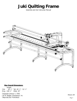
Step 1: Leg Assembly
Parts Needed:
-Frame Leg (3)
-Table Support (4)
-Table Angle Support (4)
-M6 x 16mm SBHCS (8)
-M6 x 10mm Connector Bolt (8)
1-1: Set up the Frame Leg on the left side.
Place Table Support on top of the curved tube
of the leg. Line up the holes on the table
support with the right row of holes on the
leg. Screw a M6 x 10mm Connector
Bolt into each hole, as shown in Fig. 1
1-2: Place a Table Support on
top of the back side of the Frame Leg.
Line up the holes the same way
as the previous table support. Screw
a M6 x 10mm Connector Bolt into
each hole, as shown in Fig. 1
1-3: Place a Frame Leg at the
end of the table supports,
making sure the curved tube is facing the same
direction as the left side Frame Leg. Line up the left row
of holes with the table supports and screw in the M6 x 16mm
SBHCS, as shown in Fig.1. Make sure the legs line up well, and the table supports are parallel.
Note: For assembling the crib size frame, please line up the screw holes on table supports with the left
row of holes on the middle leg, and lock them with M6x10mm Connector Bolts, as shown in Fig. 1-1.
1-4: On the front side of the frame, place a Table Support on to the top of the middle Frame Leg, line up
the holes on the table support with the other row of holes on the leg. Screw an M6 x 10mm Connector
Bolt into each hole, as shown in Fig. 1.
1-5: Place a Table Support on to the top of the back side of
the Middle Frame Leg. Line up the holes and screw a
M6 x 10mm Connector Bolt into each hole, as shown in Fig.1.
1-6: Place the right Frame Leg at the end of the unxed table
supports, oriented the the same direction as the left and
middle Frame Legs. Line up the right row of holes on the leg
with the holes on the table supports, Screw a M6 x 10mm
Connector Bolt into each hole, as shown in Fig.1.
Frame
Front
Frame Back
(2) M6 x 10mm
Connector Bolt
(2) M6 x 16mm
SBHCS
Frame Leg
Frame Leg
Table Support 1
Fig.1
Fig.1-1

pg. 6
1-7: Place a Table Angle Support at a 45
degree angle on the front top corners and
back top corners of the frame on the outside.
Line up the holes on the angle support with
one hole on the front side of the leg tube,
and one hole on the table support. Screw a
M6 x 10mm Connector Bolt into each hole, as
shown in Fig. 1-2.
Note: Attach the Table Angle Support to the
middle leg for the crib size, as shown in Fig
1-3.
Step 2: Table Brace Assembly
Parts Needed:
-Table Brace (4)
-M5 x 10mm SCHCS (8)
2-1: Attach each Table Brace to the Table
Supports by aligning the holes on the two
ends of the table brace with the flat side
facing up, screwing in the (8)-M5 x 10mm
SCHCS, as shown in Fig. 2.
Perform the same step with table braces for
crib size, only 2 table braces will be used on a
crib size frame, as shown in Fig. 2-1.
Note: Be sure the table braces are parallel to the legs.
Table Brace
M5 x 10mm
SCHCS
Fig.2
Fig.1-3
Fig.2-1
Table Angle
Support
M6 x 10mm
Connector Bolt
Fig.1-2

pg. 7
Step 3: Frame End Left & Right
Assembly
Parts Needed:
-Frame End Left (1)
-Frame End Right (1)
-M6 x 10mm Connector Bolt (8)
3-1: Put (1) Frame End Right to the right side
of the Right Leg, align the 2 groups of screw
holes with the screw holes on the leg and
screw in (4) M6 x 10mm Connector Bolt.
3-2: Assemble the Frame End Left in the same
way as Step 3 to the Left Leg, see Fig. 3-1.
Assemble the two Frame Ends in the same
way for the queen size frame and crib size
frame.
Step 4: Tracks Assembly
Parts Needed:
-Short Track Support (4)
-Long Track Support (2)
-M6 x 10mm Connector Bolt (16)
-Long Track (2)
4-1: Lay a Short Track Support on a table
support, aligning the holes in the track support
with the holes on the table support. The sides
without holes are on the outside of the frame,
see Fig. 5. For a crib size, use only the (4)
short track supports, and assemble them the
same way as king size frame.
4-2: Attach the Track support to the table
support by screwing (2) M6 x 10mm Connector
Bolt, see Fig. 4. For the crib size frame, use
the (4) Short Track Support only and assemble
the same as king size frame.
Note: Leave all bolts loose at this time.
4-3: Repeat Step 4-2 with the Long Track
Support and the other Short Track Support.
Be sure they lie in a straight line. See Fig. 4.
4-4: Press the Long Track onto the Track
Support by allowing the Track Support to be
pinched tightly by the Long Track. Be sure the
Track Support bottoms out on the Long Track.
See Fig. 4-1.
Short Track Support
Short Track Support
Long Track Support
Fig.4
Fig.4-1
M6 x 10mm
Connector Bolt
Frame End
Right
Frame End
Left
Fig.3-1
(4) M6 x 10mm
Connector Bolt
M6 x 10mm
Connector Bolt
Fig.3
Fig.4-2

pg. 8
4-5: Repeat through Steps 4-1 to 4-3 to assemble the other side of the the
track on crib size frame as well, see Fig. 4-3.
4-6: Tighten the track along the front of the frame, making sure the track
supports are even with the front edge of the frame.
Note: Leave the rear track loose at this time.
Step 5: Rail Holder Bracket
Assembly
Parts Needed:
-M6 Nylock Nut (4)
-M6 Flat Washer (4)
-Rail Holder Bracket Left (2)
-Rail Holder Bracket Right(2)
-Frame End Connector (4)
Note: The Left and Right Rail Holder
Brackets are attached at the two long
slots in the frame ends, the heights
and distances between the rail holder
brackets can be adjusted as needed.
5-1: Assemble a Frame End Connector
onto the Frame End Left so that the
screw hole in the middle of the Frame
End Connector is in line with the slot in
the middle of the Frame End Left.
5-2: Place the Rail Holder Bracket Left
onto the Frame End Left. Make sure
that the bracket is placed in the right
direction, see Fig. 5.
5-3: Place a M6 Flat Washer and a M6
Nylock Nut on the protruding bolt on the inside of the Frame End, see Fig. 5.
5-4: Assemble the other Rail Holder Bracket Right onto the Frame End Left the same way as rst one
except locating the bracket at the end of the frame end, where there is a screw hole, see Fig. 5.
5-5: Assemble the (2) Rail Holder Bracket Right on the other side of the
frame by repeating the above steps once again. See Fig. 5-1. Assembly steps
are the same for crib size frame, see Fig. 5-2.
Note: Be sure that all rail holder brackets are facing the correct direction as
shown in the picture.
Fig.5-2
Fig.4-3
Rail Holder
Bracket
Left
M6 Nylock
Nut
M6 Flat
Washer
Fig.5
M6 Nylock
Nut
M6 Flat
Washer
Rail
Holder
Bracket
Right
Fig.5-1

pg. 9
Step 6: Rails Assembly
Parts Needed:
-Rail (4)
-Rail Coupler (2)
-M5 x 10mm SBHCS (4)
-
Non-Ratchet Wheel (2)
-Ratchet Wheel
(2)
-
Ratchet Cap (2)
6-1: Put a Rail Coupler into a Rail, aligning
the two set screws on the Rail coupler with
the two bigger holes on the Rail. Tighten the
(2) M6 x 12mm set screws (pre-installed)
into the Rail through the hole. See Fig. 6.
6-2: Lock the other side of the Rail Coupler to another Rail in the same way
as Step 6-1.
6-3: Assemble the second Rail Coupler by repeating Step 6-1 and 6-2.
6-4: For the crib size frame, Steps 6-1 to 6-3 are not needed.
6-5: Insert the Non-Ratchet Wheel into one end of the rail, making sure the slot
on the rail is aligned with the Square Nut, then screw in (1) M5 x 10mm SBHCS,
as shown in Fig. 6-1.
6-6: Insert the Ratchet Wheel into the other end of the rail, make sure the slot
on the rail is aligned with the Square Nut, then screw in (1) M5 x 10mm SBHCS,
as shown in Fig. 6-2.
6-7: Repeat Step 6-5 through Step 6-6 to assemble the other rail.
Note: Assembly steps are the same for crib size frame.
6-8: Take one assembled rail, make sure that the plastic knob sticking out on
the Non-Ratchet Wheel is in line with the corresponding slot on the Rail Holder Bracket Left plastic, and
then insert the Non-Ratchet Wheel into one of the Rail Holder Bracket Left plastic, roll the rail a little bit
to make sure the Non-Rachet Wheel does not come o, as shown in Fig. 6-3.
6-9: Take the other side of the rail and place the Ratchet Wheel onto the plastic on Rail Holder Bracket
Right. Take a Ratchet Wheel Cap and snap it onto the Rail Holder Bracket Holder plastic to keep the
Rachet Wheel locked and in place, as shown in Fig. 6-4.
6-10: Repeat Steps 6-8 and 6-9 to assemble the other rail. .
M6 x 12mm
Set Screw
Rail
Fig.6
Ratchet
Cap
Fig.6-4
Fig.6-3
M5 x 10mm
SBHCS
Ratchet
Wheel
Non-Ratchet
Wheel
Fig.6-2
Fig.6-1
M5 x 10mm
SBHCS
Rail Coupler

pg. 10
Step 7: Placing the Carriage
Parts Needed:
-Carriage (1)
-Frame body Assembly (1)
- Carriage Channel Lock (1)
7-1: Remove the right rear M6 x 20mm SBHCS from the
Carriage and install the Carriage Channel Lock as shown,
see Fig.7.
7-2: Place the Carriage onto the frame as shown, see
Fig7-1.
Note: It may be neccessary to adjust the rear Carriage
wheels. Loosen the (2) M6 Connector Bolts and adjust
the Carriage to t to the track, see Fig7-2.
7-3: Align track by slowly moving the Carriage along
Plastic Track, tightening each M6 x 10mm Connector
Bolts on the rear track starting at one side of the frame
to the opposite side, see Fig 7-3
Fig.7
Carriage Channel Lock
M6 x 20mm SBHCS
Carriage
Fig.7-1
M6 Connector
Bolt
Fig.7-2
Fig.7-3
M6 x 10mm
Connector Bolt

pg. 11
Fig.8
Sewing Machine
Channel Lock
M6 x 20mm SBHCS
Carriage
Fig.9b
Top Plate Optional
Accessory
Carriage
Fig.9a
Step 8: Channel Lock Installation
Parts Needed:
-Top Plate Assembly (1) Optional
Accessory
-Frame body Assembly (1)
-Sewing Machine Channel Lock with Spacer (1)
- Carriage Channel Lock (1)
8-1a: Remove the right rear M6 x 16mm SBHCS
from the Sewing Machine and install the Sewing
Machine Channel Lock using the M6 x 20mm SBHCS
as shown, see Fig.8.
8-1b: Remove the right rear M6 x 20mm SBHCS
from the Top Plate Optional Accessory and install
the Top Plate Channel Lock using the M6 x 20mm
SBHCS as shown, see Fig.8a
Step 9: Placing your Sewing Machine
Parts Needed:
-Cam Clamp (4)
-Assembled Carriage and Frame (1)
9-1a: Place optional Top Plate Assembly
onto the frame as shown, see Fig9a.
9-1b: Place the Carriage and Sewing Machine
onto the frame as shown, see Fig9b.
Fig.8a
M6 x 20mm SBHCS
Top Plate Channel Lock
Channel Lock Washer

pg. 12
Note: It may be neccessary to adjust the Rail
Bracket Holders up to t the Sewing Machine.
Loosen the Wing Knob on each of the Rear
Rail Bracket Holders and move the Rail Bracket
Holders up. See Fig 9-1
9-1: Place your sewing machine onto the Top
Plate of the Carriage, and center it, from side
to side and from front to back.
9-2: Pull the Sewing Machine Clamp Handle
in the open position slide it into the slot on
the Top Plate until it is touching the sewing
machine. Push the handle down to lock the
Clamp into position, as shown in Fig. 9-2 and
Fig. 9-3. Repeat this with the remaining (3)
clamps.
Fig.9-2
Fig.9-3
Fig.9-4 Fig.9-5
Congratulations on the completion of the assembly of your new Start Right 2 Frame!
All that remains is to install your fabric and begin quilting!
Wing Knob
Fig.9-1

pg. 13
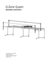
Step 10: Adjusting the Rail Holder Brackets
10-1: Position the Sewing Machine in the center of the Carriage.
10-2: Loosen the Wing Knobs on each of the Rear Rail Holder Brackets.
10-3: Adjust the Rear Rail Holder Brackets until the Take-Up Rail is centered in the
throat of the Sewing Machine. Then Re-tighten the Wing Knobs, see Fig 10.
Fig.10
Wing Knob

pg. 14
Quilting Frame Fabric Installation
With the Grace Company’s, specially designed Fabri-Fast rails, installing your fabric is easier on this
Frame than on any other frame. Each rail has a Fabri-Fast slot and accompanying tubing. These work
together to make your fabric installation much easier and faster than using tape, tacks, or Velcro®.
Before you begin, please locate the plastic Fabri-Fast tool included in your shipment.
We recommend you begin with practice material allowing you to experiment with machine settings and
stroke techniques.
NOTE: As you cut your fabric layers, we recommend making the quilt backing about 6-8” longer and
2-4” wider than your top. This will allow for a little give in the backing, especially if using thicker batting.
Rail Rotation: It is important that each rail rotates the correct direction to apply tension to
your quilt layers correctly. Light tension is applied to your quilt fabric to remove wrinkles, and to allow
the fabric to be sewn together consistently throughout the entire quilt.
The Ratchet Rail ends allow
you to limit the direction that each rail rotates. The ratchet can also be set to a neutral position
bypulling the knob up and twisting it.
Installing Fabric Layers onto the Rails
(Preview): Center your cloth lengthwise along
the rail. Using Grace’s Fabri-FastTM System, take
a piece of plastic tubing (cut to the appropriate
length), and, holding your fabric to the slot (lining
up the edge), press the tubing over the fabric and
into the slot. Use the Fabri-Fast tool to press the
rest of the tube and fabric in quickly and easily.
Methods of Installation: 1: Apply your fabric layers directly to the rails. 2: The recommended method
of installation is to use Cloth Leaders. You may make and use Cloth Leaders, or purchase them. Using
leader cloths enable you to nish your quilt completely, to the end, without having to take your quilt o
the rails. See page 13 for instructions on how to make and use cloth leaders.
5.00 13.00
3/4" Casing
3/4" Casing

pg. 15
Making Cloth Leaders
1: First, select your cloth leader material. We recommend using a good quality muslin or
similar fabric that has a good thread count. Be aware, however, that if the fabric is too
thick, it may prove more dicult getting it installed into the rail slot.
2: Surge or hem your cloth leaders on all sides.
3: Make cloth leaders in the widths shown. (The recommended length is 105”, this length will
accommodate any width of quilt that can be made on your Quilting Frame.)
4: Make a dashed line along the length of your leader about ½” in from the edge with a pen or
marker. You will use this as a guide to help you insert your leader into the slot in straight line.
(OPTIONAL: For a straighter cloth leader installation, some may consider it easier to make
a hem and then push the tubing into the hem before installing it into the slot. If you wish to do
this, create a hem on one end of each leader by folding over the fabric one inch (1”), and,
using your foot pedal as a guide, stitching the fabric together 3/4” from the fold. This will leave
about ¼” of fabric beyond the stitching. Leave the edges open on both ends. You may then slide
your tubing into the hem, Fig. CL1-1).
5: Mark each cloth leader at the center (length-wise).
6: Mark (or baste) a straight line about ½” in from the opposite (non-hemed, or non-dashed) end
of the leader. This will be the line to which you attach your fabric layer.
7: Center your cloth leader lengthwise along the rail. Using Grace’s Fabri-FastTM System, take a
piece of plastic tubing (cut to the appropriate length), and, holding your cloth leader to the slot
(lining up the dashed line), press the tubing over the leader and into the slot. Use the Fabri-Fast
tool to press the rest of the tube and fabric in quickly and easily. (If you have made a hem, line
up this hem w/ tubing over the slot and press it into the slot using the Fabri-Fast tool. 8: With
Cloth Leaders in place, pin your Quilt Fabric to the Leaders, rather than attaching it directly to the
Rails.
Installing Fabric Layers onto Rails
STEP 1: Quilt Backing to 2nd Rail
Step 1-1: To begin, determine which will be the front and back
edges of your quilt backing (make sure the backing is not wider
than your quilting frame).Note: If your backing is made up of
more than one piece of fabric, cut your selvedges o and atten
them out to allow the backing the proper give it needs.
Step 1-2: Line up the center of your fabric layer with the center
of the cloth leader on the 2nd rail. Pin the back edge of your
backing to the leader cloth. This is to be done with the nished
side of the fabric facing down. Note: Do not stretch or pull the
fabric during this process, let it lay as naturally as possible.
backing
take up
leader
1st r
ail
2nd rail
backing
1st rail
2nd rail
Fig.1-1
Fig.1-2

pg. 16
Step 1-3: Roll your leader and backing onto
the 2nd rail completely. Watch to make sure
the fabric stays lined up. Smooth out any
wrinkles as you roll by brushing the fabric
from the center out. However, be very careful
not to stretch or pull the fabric excessively.
Note: It is important that you roll the rail the
proper direction so the fabric rolls over and
onto the 2nd rail (Fig. 1-2).
Step 2: Attaching Your Quilt Layers to
The Take-Up Rail
Step 2-1: Take the top edge of the quilt
backing and pin it along the straight line of the take up rail
leader in a smooth manner, without stretching your fabric.
Smooth and drape the excess o the front of the quilting frame.
See Fig. 2-1.
Step 2-2: Next, lay your batting along the pin line of your
backing on the take up rail cloth leader. Smoothly lay it over
the quilt backing and drape the excess o the front of the
quilting frame. See Fig. 2-1.
Step 2-3: Finally, lay the quilt top over the batting along the
pin line on the take up rail cloth leader. Pin your top and batting
along the same line as your backing so that it is smooth.
Smoothly lay the rest over the batting and drape the excess o
the front of the quilting frame. See Fig. 2-1.
Step 2-4: Adjust the height of your fabric o of the throat
plate of your sewing machine. Do this by rolling the machine
to one end of the table, and adjusting the Wing Knob to move
each of the Rail Holder Brackets so that the bottom of the quilt
is 1/4" above the throat of your sewing machine base and
parallel to the throat plate. See Fig. 2-2.
Step 2-5: Roll your sewing machine to the other end of the
table and repeat Step 2-4.
Rolling fabric
● When you have completed your work area and are ready to roll to the next, simply disengage the
ratchet stop on the front rail allowing it to roll freely. Then, with one or both hands, roll the Take-Up Rail
forward, rolling the completed work area onto that Rail. Repeat Step 2-4 as needed.
Step 1: Install quilt backing to 2nd rail and roll up.
Step 2:
Step 3:
Step 4:
Attach quilt backing to take up rail.
Attach batting to take up rail.
Attach quilt top to take up rail.
backing
top fabric
batting
2nd rail
1st rail (take up rail)
Fig.2-1
1/4”
Rail Holder Bracket
Fabric
Fig.2-2

pg. 17
Bungee Clamp
Bungee Button
Fig.3-1
Step 3-1: Attach the Bungee Clamps
to the Rail Holder Brackets by putting
the cord through the holes. Attach the
Bungee Clamps to the fabric and pull
evenly and pull cord down to lock into
place. Secure using the Bungee Buttons
as shown. See Fig. 3-1.
Step 3: Attaching the Bungee Clamps
Step 4: Channel Lock Setup
Step 4-1: Rotate the Channel Lock
handle down. To adjust the Channel
Lock, loosen the upper nut. Twist the
Rubber Foot clockwise until it is snug
against the track. Turn the upper nut
counter clockwise until it is snug against
the channel lock barrel. See Fig 4-1.
Step 4-2: Repeat Step 4-1 for the
Carriage Channel Lock.
Note: The Channel Locks will be used for
straight lines. To create a straight line
along the length of the frame, rotate the
handle of the Sewing Machine Channel
Lock down. To create a straight line
along the length of the Carriage, rotate
the handle of the Carriage Channel Lock
down.
Upper Nut
Channel Lock Barrel
Track
Fig.4-1

pg. 18
Start-Right Cloth Leaders
Quilting Accessories
The following accessories are available for your new SR-2 Machine Quilting Frame.
Each is designed to make your quilting projects easier and even more beautiful.
They can all be purchased through your GraceFrame dealer, or directly from The Grace Company.
www.graceframe.com 1-800-264-0644
Table-Top Inserts
Table-Top insers add more
working area to your frame.
Use them for the Plastic
Pattern Perfect, or as a place to
put pantographs to be traced
with Gracie Laser.
Sure Stitch Regulator
The GraceSure Stitch is both a stitch regulator
and constant stitch speed control. As you
speed up and slow down in Stitch Regulation
Mode, so will your machine, keeping all of
your stitches the same length. You can also use
the SureStitch for a constant speed that you can
adjust with the push of a button.
Start-Right Cloth Leaders save time
during your project and help you
attach fabric to your frame easily and
accurately. The included three cloth
leaders are printed with precise
guide marks and pin lines.
Plastic Pattern Perfect
For perfect patterns every time, use
the Plastic Pattern Perfect! The stylus
attaches right to your carriage, and
then guides your machine through the
pattern templates as you move the
carriage.
Note: Table-top inserts must be
installed to use these templates.
Gracie Laser
Plastic Pattern Perfect
Additional Templates
6 additional patterns to choose from,
with more being added all the time!
These additional patterns work with
the stylus from the basic Plastic
Pattern Perfect. They come in a set
of 2 or a set of 6 for your whole
frame.
www.graceframe.com 1-800-264-0644Order online, or give us a call at:
Pattern tracing is easier than ever before with
the Gracie Laser.
•Attaches to the front or back of your frame’s
carriage!
•Swivel and lock the stylus at any angle
•Battery powered, no cords to get in the way
•Comes with four different laser tips to control
the size of the laser.

pg. 19

pg. 20
The Grace Company
2225 South 3200 West
Salt Lake City, UT 84119
Phone: 1-800-264-0644
Fax: 801-908-8888
www.graceframe.com
/