Page is loading ...

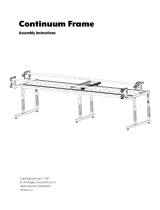
Assembly Instructions
Copyright September 27, 2019
Grace Company
(Reproduction Prohibited)
Version 2.15
Continuum Frame

Table of Contents ...................................................................................................................... i
Warranty ..................................................................................................................................iii
Continuum Frame Configurations
8 Foot Frame with Accessories ..................................................................................................iv
10 Foot Frame with Accessories .................................................................................................v
Parts Lists
Box 1 ......................................................................................................................................vi
Box 2 (4 Foot) or Box 2 (5 Foot) ................................................................................................ ix
Box 3 (4 Foot) or Box 3 (5 Foot) ................................................................................................ ix
Box 4 .......................................................................................................................................x
Frame End Assembly Instructions
Step 1: Table Height Setup ....................................................................................................... 1
Step 2: Extension Arm Adjustment ............................................................................................ 2
Table Sections and Rail Assembly Instructions
Step 3: Table Setup .................................................................................................................. 3
Step 4: Corner Brace Installation ............................................................................................... 5
Step 5: Middle Leg Brace Installation ......................................................................................... 6
Step 6: Track Support Setup (8 Foot and 10 Foot Configurations) ................................................. 7
Step 7: Rail Support Installation ................................................................................................9
Step 8: Ratchet Rail Assembly .................................................................................................. 10
Step 9: Hand Wheel Assembly .................................................................................................11
Step 10: Rail Installation ..........................................................................................................12
Carriage Installation Instructions
Step 11: Continuum Carriage Assembly ..................................................................................... 14
Step 12: Midarm Sewing Machine Installation ............................................................................16
Step 13: Longarm Sewing Machine Installation ..........................................................................17
Step 14: Install Take Up Rail ....................................................................................................18
i
|Table of Contents Continuum Frame - Queen Assembly

ii
Table of Contents ...................................................................................................................... i
Warranty ..................................................................................................................................iii
Continuum Frame Configurations
8 Foot Frame with Accessories ..................................................................................................iv
10 Foot Frame with Accessories .................................................................................................v
Parts Lists
Box 1 ......................................................................................................................................vi
Box 2 (4 Foot) or Box 2 (5 Foot) ................................................................................................ ix
Box 3 (4 Foot) or Box 3 (5 Foot) ................................................................................................ ix
Box 4 .......................................................................................................................................x
Frame End Assembly Instructions
Step 1: Table Height Setup ......................................................................................................19
Step 2: Extension Arm Adjustment ...........................................................................................20
Table Sections and Rail Assembly Instructions
Step 3: Table Setup .................................................................................................................21
Step 4: Corner Brace Installation ..............................................................................................22
Step 5: Rail Support Installation ...............................................................................................23
Step 5: Ratchet Rail Assembly .................................................................................................. 24
Step 7: Hand Wheel Assembly .................................................................................................24
Step 8: Rail Installation ...........................................................................................................25
Carriage Installation Instructions
Step 9: Carriage Installation ..................................................................................................... 27
Step 10: Midarm Sewing Machine Installation ............................................................................28
Step 11: Longarm Sewing Machine Installation ..........................................................................29
Step 12: Install Take Up Rail ....................................................................................................30
Fabric Installation
Step 1: Leader Cloth Set Up .....................................................................................................31
Step 2: Fabric Installation ........................................................................................................31
Step 3: Bungee Clamp Installation ............................................................................................33
Step 4: Care and Use ..............................................................................................................33
Step 5: Leveling the Frame ......................................................................................................34
|Table of Contents Continuum Frame - Crib Assembly

X
?
Warranty
1-800-264-0644
Warranty Information for your Continuum Quilting Frame
The Continuum Quilting Frame has a One-Year limited warranty on all parts. The Grace Company will
repair or replace, at its discretion, any part with problems due to our manufacturing or defects in
materials. This warranty does not cover parts damaged through misuse, improper storage, improper
assembly, loss, natural events, and willful destruction. Parts must be returned to the Grace Company,
shipping prepaid, before we can repair or replace them. We will promptly return the repaired/re-
placed part at our expense if done within a year of the purchase date.
iii

8 Foot Frame with Accessories
Backing Rail
Quilt Top Rail
Take-Up Rail
8 Foot Rail Assemblies
8 Foot Track Support Assembly
Idler Rail
(Optional Accessory)
Batting Rail
(Optional Accessory)
Continuum Frame Congurations
Can be assembled as 4 Foot
iv

Continuum Frame Congurations
10 Foot Frame with Accessories
Backing Rail
Quilt Top Rail
Take-up Rail
10 Foot Rail Assemblies
10 Foot Track Support Assembly
Idler Rail
(Optional Accessory)
Batting Rail
(Optional Accessory)
v
Can be assembled as 5 Foot

Parts List Box 1 Continuum Frame
Inner Box 1
Left Leg
(1)
Right Leg
(1)
Middle Leg
(1)
Middle Leg Brace
(2)
Corner Brace
(4)
vi

Parts List Box 1 Continued Continuum Frame
Inner Box 1 Continued
Non-Ratchet Front Rail Support
(1)
Ratchet Front Rail Support
(1)
Ratchet Back Rail Support
(1)
Non-Ratchet Back Rail Support
(1)
Bungee Clamp Assembly
(4)
Track Support Connector
(2)
vii
Hand Wheel Knob
(1)
Hand Wheel
(1)
Hand Wheel Collar Pre-installed
(1)

Parts List Box 1 Continued Continuum Frame
14
17
Flat Washer
(8)
M6 x 6mm Set Screw
(8)
M8 x 16mm SBHCS
(46)
M8 x 60mm SBHCS
(8)
M10 x 115mm SBHCS
(1)
Hand Wheel Shoulder Bolt
(1)
10mm & 13mm Double Open End Wrench
(1)
5mm Allen Wrench
(1)
6mm Allen Wrench
(1)
3mm Allen Wrench
(1)
4mm T-Handle Allen Wrench
(1)
14mm & 17mm Double Open End Wrench
(1)
viii

Parts List Box 2 (4 Foot) or Box 2 (5 Foot) Continuum Frame
Table Section
(2)
Long Plastic Track
(4)
Short Plastic Track
(4)
Ratchet Rail Section
(3)
Floating Rail Section
(3)
Rail Coupler
(3)
Parts List Box 3 (4 Foot) or Box 3 (5 Foot) Continuum Frame
Leader Cloth Set
(1)
ix

Carriage
(1)
M6 x 20mm SBHCS
(2)
Channel Lock
(2)
Parts List Box 4 Continuum Frame
Channel Lock Washer
(2)
x

Queen Assembly
Crib Assembly
See pages 1-16 for the Continuum Frame Queen Assembly.
See pages 17-28 for the Continuum Frame Crib Assembly.
See pages 29-33 for the Continuum Frame Fabric Installation and the Care and Use
Instructions.
xi
Configurations

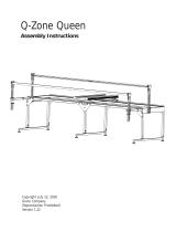
Average user
height is third hole
from the bottom
Centering
Screws
Height
Screws
Nut
Nut
Washer
Washer
Centering
Screws
Height
Screws
Nut
Nut
Washer
Washer
1-3 Replace each height screw and tighten each
centering screw.
Note: Repeat for all legs.
Step 1 - Table Height Setup
Middle Leg (1)
Left Leg (1)Right Leg (1)
Parts Needed:
1-1 Remove height screws and loosen centering
screws.
Note: Right Leg Shown. Repeat for all legs.
1-2 Adjust table height by sliding legs up or down.
Tools Needed:
5mm Allen Wrench
10mm & 13mm
Double Open
End Wrench
Frame End Assembly - Queen Assembly
1

Loosen Set
Screws
4mm Allen
Wrench
Extension
Arm Slot
Tighten Set
Screws
4mm Allen
Wrench
Step 2 - Extension Arm Adjustment
2-1 Loosen set screws.
Tools Needed:
4mm Allen Wrench
2-2 Extend to the rst slot for machines with throat
less than 16”.
Extend to the second slot for machines with throat
greater than 16”.
Frame End Assembly - Queen Assembly
2

Step 3 - Table Setup
M8 x 16mm
SBHCS (12)
Middle Leg (1)Left Leg (1)Right Leg (1)Table Section (2)
Tools Needed:
4mm T-Handle Allen Wrench
5mm Allen Wrench
M6 x 10mm
Connector Bolt
4-1 Remove the Track Supports from the (2) Table Sections for 8 foot and 10 foot congurations.
M6 x 10mm
Connector Bolt
Table Sections and Rail Assembly - Queen Assembly
3

Middle Leg
Right Leg Assembly
Table Section
M8 x 16mm
SBHCS
M8 x 16mm
SBHCS
4-2 Install (1) Table Section to the Right Leg Assembly and the Middle Leg.
Note: Press table against Right Leg Assembly.
Note: Leave all bolts loose until step 6.
Middle Leg
Left Leg Assembly
Table Section
M8 x 16mm
SBHCS
M8 x 16mm
SBHCS
4-3 Install (1) Table Section to the Left Leg Assembly and the Middle Leg.
Note: Press table against Left Leg Assembly.
Table Sections and Rail Assembly - Queen Assembly
4

Corner
Brace
Tools Needed:
5mm Allen Wrench
M8 x 16mm
SBHCS
Parts Needed:
Step 4 - Corner Brace Installation
Corner Brace (4)
M8 x 16mm
SBHCS (16)
5-1 Install each Corner Brace with (4) M8 x 16mm SBHCS.
Note: Repeat for all (4) corners.
Table Sections and Rail Assembly - Queen Assembly
5

M8 x 16mm
SBHCS
M8 x 16mm
SBHCS
M8 x 16mm
SBHCS
M8 x 16mm
SBHCS
M8 x 16mm
SBHCS
Middle Leg
Brace
6-2 Install (12) M8 x 16mm SBHCS.
Note: Tighten all bolts at this time.
Tools Needed:
5mm Allen Wrench
Step 5 - Middle Leg Brace Installation
Middle Leg Brace (2)
M8 x 16mm
SBHCS (12)
6-1 Place (2) Middle Leg Brace into Position.
Note: Repeat for opposite side.
Parts Needed:
Table Sections and Rail Assembly - Queen Assembly
6

Long Plastic Track
Track Support
Connector
Track Support
Extrusion
M6 x 6mm
Set Screw
M6 x 6mm
Set Screw
Track Support
Extrusion
Tools Needed:
4mm T-Handle Allen Wrench
Track Support
Connector (2)
M6 x 6mm Set
Screw (8)
Long Plastic Track (4)
Track Support
Extrusions (4)
(Removed In Step 4)
M6 x 10mm
Connector Bolt (16)
Step 6 - Track Support Setup (8 foot and 10 foot)
Parts Needed:
7-1 Assemble Track Support making sure there is no gap between the Track Support Extrusions. Install
the Long Plastic Track into the Track Support Extrusions.
Note: Tighten one side of Track Support Extrusion to the Track Support Coupler, then insert the second
Track Support Extrusion to Track Support Coupler and tighten.
Track Sections Assembly - Queen Assembly
7

(16) M6 x 10mm
Connector Bolt
Track Support
Assembly
7-3 Secure Track Support Assembly to the Table.
Note: Repeat for Back Track Support and tighten M6 x 10mm Connector Bolts with Track parallel to
the back of the Table. Do not tighten M6 x 10mm connector bolts on Front Track Support until after
carriage installation.
Track Sections Assembly - Queen Assembly
8
/