Page is loading ...

INSTALLATION AND PROGRAMMING GUIDE
9800INT Series
Graphic Touchscreen Keypad


TABLE OF CONTENTS
About the Keypad ...................................... 1
Keypad Features ......................................... 2
Programmable Carousel Menu ................................. 3
Number Pad Features ................................4
Select a Location ........................................ 7
Install the Keypad ....................................... 8
Remove the Cover ......................................................... 8
Power the Keypad ......................................................... 9
Mount the Keypad ........................................................ 12
Install the Tamper .........................................................12
Connect the Keypad .................................................... 13
Program the Panel .................................... 15
Device Setup ...................................................................15
Device Number ..................................................................15
Device Name ....................................................................... 15
Device Type ......................................................................... 16
Communication Type .......................................................16
Serial Number ..................................................................... 16
Supervision Time ...............................................................16
Program the Keypad ................................ 17
Keypad Options ............................................................. 17
Default Keypad Message ................................................17
Arm Panic Keys .................................................................. 17
Arming/Disarming Wait Time .....................................18
Enable Tamper ...................................................................18
Card Formats ......................................................................19
Require Site Code ............................................................ 23
Site Code Display ............................................................. 23
No Communication with Panel ...................................24
System Type ....................................................................... 26
Dealer Logo ........................................................................ 26
Dealer Info ..........................................................................26
Carousel Z-Wave Items .................................................. 27
Shortcut Items ...................................................................28
Select Language ............................................................... 28
Additional Programming ........................ 29
Update the Keypad .....................................................29
Test the Keypad ....................................... 30
Keypad Diagnostics ................................................... 30
Test the Credential Reader .......................................... 30
Exit the Installer Options Menu ................................. 30

End User Training ..................................... 31
Access the User Menu ................................................. 31
Arm and Disarm the System ....................................32
Touchless Arming .......................................................33
Use Access Control .....................................................33
Icon Reference ..............................................................36
Change System Wi-Fi Password ............................38
Clean the Keypad ........................................................ 40
Replace the Keypad Battery ..................................... 41
Public Card Formats ............................... 42
Credentials ............................................... 43
Ordering Information .............................. 44
Keypads .......................................................................... 44
Accessories.................................................................... 44
Compliance Specifications..................... 45
International Certifications .................... 46

9862INT Series Installation and Programming Guide 1
ABOUT THE KEYPAD
9862INT Series Wireless Graphic Touchscreen Keypads oer flexible features and
functionality. Each keypad provides:
• AC Power/Armed LED
• Full color touchscreen display
• Built-in proximity card reader
• Internal speaker
• Wireless communication
• Internal rechargeable 3.7V lithium battery
• microSD card slot for customized logo
• Icon-driven operation
• Wall tamper protection
• Optional backboxes for conduit or wall-mount applications

9862INT Series Installation and Programming Guide 2
KEYPAD FEATURES
Figure 1: Keypad Features
Armed/Power LEDs &
Proximity Reader
Dealer Logo Carousel Menu
Local
Weather
Interactive
Arming/
Disarming
Shield
Press the
Navigation
Arrows or touch
and drag the
menu to scroll
microSD
Card Slot

9862INT Series Installation and Programming Guide 3
Figure 2: Keypad Options
Programmable Carousel Menu
The carousel menu allows the user to pick and choose what displays within the carousel
menu on the home screen. Press Options in the carousel menu. From here, adjust the
keypad screen brightness, keypad tone, and keypad volume. Press a box under Display
In Menu to select that option to display in the carousel menu. Press that box again to
deselect that option. See Figure 2.
A Brightness setting of 1 allows the keypad display to turn o automatically after a brief
period of inactivity. The Arm/Disarm LED remains lit. A Brightness setting of 0 allows both
the keypad display and LED to turn o automatically after a period of inactivity. To wake
the display, tap any part of the touchscreen surface.

9862INT Series Installation and Programming Guide 4
Select Areas
1 2 3 4
5 6 7 8
9 0
CMD
ABC DEF GHI JKL
MNO PQR STU VWX
YZ
CMD
Back Arrow
Return
to Home
Screen
1 432
Figure 3: Number Pad
NUMBER PAD FEATURES

9862INT Series Installation and Programming Guide 5
Number Pad
1. Choose a character from the table. Use the Greek Characters table if Greek was
selected as the keypad language setting. Refer to Select Language. See Table 1.
2. Identify the Number the character correlates with and press that number on the
number pad.
3. Identify the Select Area for the character and press that select area on the keypad.
Press that select area again for the lowercase letter (Latin only). See Table 2. Refer
to Figure 3.
4. When the desired character displays on the keypad, return to Step 1 to enter
another character or press CMD if finished.
Table 1: Greek Characters Table 2: Latin Characters
NUMBER
SELECT AREA
1 2 3 4
1 Α Β Γ ( [ {
2 Δ Ε Ζ ) ] }
3 Η Θ Ι ! ^ ~
4 Κ Λ Μ ? “ |
5 Ν Ξ Ο / \ `
6 Π Ρ Σ & $
7 Τ Υ Φ @ %
8 Χ Ψ Ω , =
9 Space Space Space : _ ;
0 - + . ‘ * < # >
NUMBER
SELECT AREA
1 2 3 4
1 A B C ( [ {
2 D E F ) ] }
3 G H I ! ^ ~
4 J K L ? “ |
5 M N O / \ `
6 P Q R & $
7 S T U @ %
8 V W X , =
9 Y Z Space : _ ;
0 - + . ‘ * < # >

9862INT Series Installation and Programming Guide 6
Figure 5: Standard Keyboard
1 2 3 4
5 6 7 8
9 0
CMD
ABC DEF GHI JKL
MNO PQR STU VWX
YZ
Select Areas
Return
to Home
Screen
1 43
Figure 4: Number Pad
2
Uppercase/
Lowercase
Letters
Special
Characters
Number Pad

9862INT Series Installation and Programming Guide 7
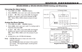
9862INT Series Wireless Graphic Touchscreen Keypads provide a built–in survey capability
to allow one person to confirm keypad communication with the wireless receiver or panel.
This allows you to determine the best location for the keypad.
1. Press Options in the carousel menu.
2. Press the installer options icon at the bottom-left corner of the screen.
3. Enter 3577 (INST) and press CMD.
4. Press the select key under KPD RF to start the survey communication. The keypad
displays its wireless serial number and RF SURVEY. Determine if communication is
confirmed or faulty.
Confirmed: When successful communication has been established, the AC
Power/Armed LED turns blue.
Faulty: If communication has not been established, the keypad AC
Power/Armed LED turns red. Relocate the device or wireless receiver until the
survey LED confirms clear communication.
SELECT A LOCATION

9862INT Series Installation and Programming Guide 8
INSTALL THE KEYPAD
Remove the Cover
The keypad housing is made up of two parts:
the cover, which contains the circuit board and
components, and the base.
1. Insert a flat screwdriver into one of the
slots on the bottom of the keypad and lift
the screwdriver upward. Repeat with the
other slot.
2. Separate the cover from the base and
set the cover containing the keypad
components aside. See Figure 6.
1
Figure 6: Separate the
Keypad Housing
Cover
Base

9862INT Series Installation and Programming Guide 9
2
Power the Keypad
Connect the DC power supply positive and negative wires
to the PCB terminal block. See Figure 7.
In addition to powering the keypad, the power supply also
charges the internal back-up battery.
Warning: Observe Polarity. Connect the black (-) wire
to the negative terminal on the power supply.
Connect the ribbed black (+) wire to the positive
terminal on the power supply.
Plug the power supply into a 240VAC, 50Hz dedicated
outlet not controlled by a switch.
Note: Do not remove the PCB from the keypad
housing to install the power supply connector.
When the power supply wires are connected to the keypad
and the power supply is plugged in, the internal battery is automatically connected.
The keypad can operate from battery only as long as the power supply is connected
to the keypad.
Figure 7: Connecting
the Power Supply
INT
Ribbed Black (+)
Black (-)

9862INT Series Installation and Programming Guide 10
Standby Battery
The keypad rechargeable battery provides 12hours of backup battery power when
primary AC power is not available. It is shipped already installed inside the keypad. The
battery is intended for backup power only and not to operate the keypad on a daily basis.
If the battery is low, or not plugged into the internal battery connector, a low battery
condition is indicated by the panel. When the battery falls below 3.60V, a red battery icon
displays on the main screen and KEYPAD - LOBAT will display in the Status List. To restore
the keypad from a low battery state, the voltage must be above 3.62V.
Use the following steps to replace the battery. DMP recommends replacing the battery
every 3years under normal use.
Note: If removing the keypad from service, disconnect the power supply connector
from the back of the keypad to avoid discharging the battery.
Replace the battery
1. Disconnect the battery lead connector from the keypad battery header.
2. Peel o the old battery from the keypad PCB.
3. Observe polarity and connect the battery lead connector to the keypad battery
header. See Figure 8.
4. Place the new battery (DMP Model 9800BAT) on the keypad PCB with the
included double-sided tape. Properly dispose of the used battery.

9862INT Series Installation and Programming Guide 11
Warning: Risk of fire, explosion, and burns. Do not disassemble, heat above
212°F (100°C), or incinerate.
Figure 8: Battery Connection
Battery
Battery
Connection
INT
Ribbed Black (+)
Black (-)

9862INT Series Installation and Programming Guide 12
Mount the Keypad
Secure the keypad base to the wall ensuring that the wall tamper switch makes
proper contact with the wall. Use the supplied screws in the mounting hole locations.
See Figure 9 for mounting hole locations.
Note: For Security Grade
2, Environmental Class II
installations, use the
shaded holes in Figure 9
for installation.
Install the Tamper
The keypad base includes a
tamper feature.
1. Insert the included
tamper puck into the
base.
2. Secure the tab to the
wall with a #6screw.
3
Figure 9: Tamper Protection
Surface and Backbox Mounting Holes
Surface and Backbox Mounting Holes
Tamper Puck

9862INT Series Installation and Programming Guide 13
Connect the Keypad
Connect the keypad to the panel by using one of the following options: Wireless
Keypad Association, Auto Pairing, or manually at the keypad in Device Setup. A
maximum of seven keypads can be paired with each panel.
Wireless Keypad Association
XTLplusINT/XTLtouchINT
1. Press Options in the carousel menu.
2. Press the installer options icon at the bottom-right corner of the screen.
3. Enter 3577 (INST) and press CMD.
4. Press KPD RF to start the RF survey communication. The keypad displays its
wireless serial number and RF SURVEY. When successful communication has
been established, the AC Power/Armed LED turns blue. If communication has
not been established, the LED turns red.
XT30INT/XT50INT or XR150INT/XR550INT Series Panels
Reset the panel three times. The yellow LED at the top of the panel will begin flashing
between each press. Wait for sixty seconds. When communication is confirmed, the
LED will turn green and will stay on steady.
4

9862INT Series Installation and Programming Guide 14
Auto Pair
Auto pairing automatically connects your keypad to the panel. After powering the
XTLplusINT or XTLtouchINT and the keypad, the keypad displays PairingKeypad With
System... and a ten minute pairing timer begins.
Confirmed: The keypad home screen displays, signaling that pairing is complete.
Faulty: The keypad displays Pairing Failed, followed by the Reset screen. Reset your
panel and press Pair to restart the pairing process. The panel will auto pair with
wireless keypads until it pairs with four keypads or until ten minutes have passed.
Device Setup
1. Program the keypad as a device in DEVICE SETUP.
2. Enter the eight-digit SERIAL# and continue to program the device as directed in
the appropriate panel programming guide.

9862INT Series Installation and Programming Guide 15
PROGRAM THE PANEL
If using an XT Series International Panel, enter 665 (PRO) then press CMD at the keypad
to access the PROGRAMMER menu. If using an XR Series International Panel, enter
6653 (PROG) then press CMD.
After completing each of the following steps, press CMD to advance to the next option.
Refer to the panel programming guide as needed.
DEVICE SETUP
Advance to DEVICE SETUP, then press a select area to enter
the setup menu.
Device Number
Set the keypad address at 1-16 for XR550 Series panels or 1-8
for other compatible panels.
Device Name
Press any select area, then enter a name for the wireless
keypad.
DEVICE SETUP
DEVICE SETUP
DEVICE NO: -
DEVICE SETUP
*UNUSED*

9862INT Series Installation and Programming Guide 16
Device Type
For use as a standard keypad, select KPD. For use as an access
control keypad, press any select area, then select DOOR.
Communication Type
Press any select area, then select WLS (Wireless) as the
communication type.
Serial Number
Enter the eight-digit wireless serial number. Range is
14500000-14999999.
Supervision Time
Press any select area and choose a supervision time. Options
are 0, 60, or 240 minutes.
DEVICE SETUP
TYPE: KEYPAD
DEVICE SETUP
COMM TYPE: WLS
DEVICE SETUP
SERIAL#:-
DEVICE SETUP
SUPRVSN TIME: 240
Configure additional options as needed. To configure custom card options for the keypad,
do not program CARD OPTIONS in Device Setup.
/