Page is loading ...

INSTALLATION AND PROGRAMMING GUIDE
7800 International Series
Graphic Touchscreen Keypad


TABLE OF CONTENTS
About the Keypad ...................................... 1
Keypad Features ......................................... 2
Programmable Carousel Menu ................................. 3
Enter Characters .........................................4
Install the Keypad ....................................... 6
Remove the Cover ......................................................... 6
Wire the Keypad............................................................. 7
Wire for Access Control .............................................. 9
Wire the Electronic Lock ..........................................10
Wire the 333 Suppressor ...........................................10
Mount the Keypad .................................... 12
Tamper Protection ........................................................ 12
Program the Panel .................................... 14
Device Setup ...................................................................14
Device Number ..................................................................14
Device Name .......................................................................14
Device Type ......................................................................... 15
Communication Type (Door) ........................................15
Program the Keypad ................................ 16
Current Keypad Address ................................................ 16
Keypad Mode ......................................................................17
Default Keypad Message ................................................17
Arm Panic Keys .................................................................. 17
Activate Zone 2 Bypass ..................................................18
Activate Zone 3 Exit ........................................................19
Arming/Disarming Wait Time .....................................20
Security Grade ..................................................................20
Any Card Format ...............................................................21
Card Formats ...................................................................... 21
Require Site Code ............................................................ 24
Number of User Code Digits .......................................25
No Communication with Panel ...................................25
System Type .......................................................................27
Dealer Logo ........................................................................ 27
Dealer Info ..........................................................................27
Carousel Z-Wave Items ..................................................28
Shortcut Items ...................................................................29
Select Language ............................................................... 29
Update the Keypad ..........................................................31

Test the Keypad ........................................32
Keypad Diagnostics ....................................................32
Zone Test ............................................................................. 32
Test the Credential Reader ...........................................32
End User Training .....................................33
Access the User Menu ................................................ 33
Arm and Disarm the System ....................................34
Use Access Control .....................................................35
Touchless Arming .......................................................35
Change System Wi-Fi Password ............................39
Clean the Keypad ..........................................................41
Wiring Specifications.............................. 42
Ordering Information .............................. 46
Keypads ...........................................................................46
Accessories.....................................................................46
Compliance Specifications......................47
Keypad Specifications................................................47
Compatibility ................................................................48
What Is Included? ........................................................48
International Certifications .................... 49

7800INT Series International Installation and Programming Guide | Digital Monitoring Products, Inc. 1
ABOUT THE KEYPAD
7800INT Series International Graphic Touchscreen Keypads oer flexible features and
functionality. Each keypad provides optional panic keys, an AC Power/Armed LED, an
internal speaker, a simple terminal connection to a 4-wire keypad bus, and optional
back boxes for conduit or wall mount applications. Each model provides its own distinct
functionality.
7873-WINT
Provides a built-in proximity card reader
designed to read proximity credentials.
Provides four fully-programmable ClassB,
Style A, supervised, power limited
protection zones that can be programmed
for a variety of burglary and access control
applications.
Provides a door strike relay and allows
Wiegand input from external card readers.
7872-WINT
Provides a built-in proximity card reader
designed to read proximity credentials.
Provides four fully-programmable ClassB,
Style A, supervised, power limited
protection zones that can be programmed
for a variety of burglary and access control
applications.

Digital Monitoring Products, Inc | 7800INT Series International Installation and Programming Guide 2
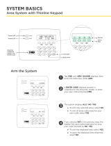
KEYPAD FEATURES
Figure 1: Keypad Features
Armed/
Power LEDs
Dealer Logo Carousel Menu
Local
Weather
Interactive
Arming/
Disarming
Shield
Press the
Navigation
Arrows or touch
and drag the
menu to scroll
microSD
Card Slot
Proximity
Read Area

7800INT Series International Installation and Programming Guide | Digital Monitoring Products, Inc. 3
Programmable Carousel Menu
Pick and choose what displays within the carousel menu on the home screen. Press
Options in the carousel menu to adjust the keypad screen brightness, tone, and volume.
Display custom options in the carousel menu by selecting and deselecting the appropriate
choices under Display In Menu. See Figure 2.
A Brightness setting of 1 allows the keypad display to turn o automatically after a brief
period of inactivity. The Arm/Disarm LED remains lit. A Brightness setting of 0 allows both
the keypad display and LED to turn o automatically after a period of inactivity. To wake
the display, tap any part of the touchscreen surface.
Display In Menu
Chime
Reset
Brightness
Tone
Volume
Easy Exit
Check In
Figure 2: Keypad Options

Digital Monitoring Products, Inc | 7800INT Series International Installation and Programming Guide 4
ENTER CHARACTERS
Number Pad
1. Choose a character from the table. Use the Greek Characters table if the keypad
language setting is Greek. Refer to Select Language. See Table 1.
2. Identify the Number the character corresponds with and press that number on the
number pad.
3. Identify the Select Area for the character and press that select area on the keypad.
Press that select area again for the lowercase letter (Latin only). See Table 2. Refer
to Figure 3.
4. When the desired character displays on the keypad, return to Step 1 to enter
another character or press CMD if finished.
Table 1: Greek Characters Table 2: Latin Characters
NUMBER SELECT AREA
1 2 3 4
1 Α Β Γ ( [ {
2 Δ Ε Ζ ) ] }
3 Η Θ Ι ! ^ ~
4 Κ Λ Μ ? “ |
5 Ν Ξ Ο / \ `
6 Π Ρ Σ & $
7 Τ Υ Φ @ %
8 Χ Ψ Ω , =
9 SPACE SPACE SPACE : _ ;
0 - + . ‘ * < # >
NUMBER SELECT AREA
1 2 3 4
1 A B C ( [ {
2 D E F ) ] }
3 G H I ! ^ ~
4 J K L ? “ |
5 M N O / \ `
6 P Q R & $
7 S T U @ %
8 V W X , =
9 Y Z SPACE : _ ;
0 - + . ‘ * < # >

7800INT Series International Installation and Programming Guide | Digital Monitoring Products, Inc. 5
Select Areas
Return
to Home
Screen
1 43
Figure 3: Number Pad
2
Figure 4: Standard Keyboard
1 2 3 4
5 6 7 8
9 0 CMD
ABC DEF GHI JKL
MNO PQR STU VWX
YZ
Number Pad
Uppercase/
Lowercase
Letters
Special
Characters

Digital Monitoring Products, Inc | 7800INT Series International Installation and Programming Guide 6
INSTALL THE KEYPAD
Remove the Cover
The keypad housing is made up of two parts:
the cover, which contains the circuit board and
components, and the base.
To separate the keypad cover from the base, insert
a slotted-tip screwdriver into one of the slots on
the bottom of the keypad and lift the screwdriver
upward. Repeat with the other slot. Separate the
cover from the base and set the cover containing the
keypad components aside. See Figure 5.
1
Figure 5: Separate the
Keypad Housing
Cover
Base

7800INT Series International Installation and Programming Guide | Digital Monitoring Products, Inc. 7
Wire the Keypad
Each keypad model has specific wiring assignments. All zones are supervised and
suitable for burglary applications. The maximum zone line impedance is 100Ohms.
Ground fault is detected at 1420Ohms or less. Locate your keypad model below
and see Figure 6 to wire the keypad. See Wiring Specifications for additional wiring
information.
Models 7872-WINT
Use a 4-wire cable for panel keypad bus connection and perform the following
connections:
• Connect the red wire to panel terminal 7.
• Connect the yellow wire to panel terminal 8.
• Connect the green wire to panel terminal 9.
• Connect the black wire to panel terminal 10.
Models 7873-WINT
Use a 4-wire cable as needed for keypad bus and zone input connections. Use a
5-wire cable for external card reader connection. Use 1k Ohm EOL resistors DMP
Model 311 on keypad zones 1-4. The following are optional 7873-WINT zone input
connections for access control:
• Zone 1: Brown White/White Brown
• Zone 2: Red White/White Red (Zone 2 Bypass)
• Zone 3: Orange White/White Orange (REX)
• Zone 4: Yellow White/White Yellow
2

Digital Monitoring Products, Inc | 7800INT Series International Installation and Programming Guide 8
Figure 6: Access Control Wiring
Green/White* - Connect Reader Data 0
White - Connect Reader Data 1
Orange - Door Strike Normally Open
Gray - Door Strike Common
Violet - Door Strike Normally Closed
Black – Ground
Green – Send Data
Yellow – Receive Data
Red – Keypad Power
– Yellow & White
Zone 4
– Orange & White
Zone 3 (REX)
– Red & White
Zone 2
– Brown & White
Zone 1 (7/0 Panic)
NC
C
NO
WHT
GRN
Z4 -
Z4 +
Z3 -
Z3 +
Z2 -
Z2 +
Z1 -
Z1 +
BLK
GRN
YEL
RED
External Card
Reader
To Panel Keypad Bus To DMP Device
Keypad, Zone Expander, etc.
s
s
*Only the green/white,
white, black, and red
wires connect to the
external card reader.
1k Ω EOL
s
s
1k Ω EOL
s
s
1k Ω EOL
s
s
1k Ω EOL

7800INT Series International Installation and Programming Guide | Digital Monitoring Products, Inc. 9
3Wire for Access Control
Internal Access Control Reader
7873-WINT and 7872-WINT keypads provide a built-in proximity card reader that is
compatible with most standard 125kHz proximity credentials. An external 13.56MHz
proximity reader can be connected and will be compatible with 13.56MHz proximity
credentials. For a list of publicly supported card formats, see Public Card Formats.
Note: Some proximity credentials are not compatible with DMP proximity
keypads. Thoroughly test the intended proximity credentials with the application
before installation. DMP does not guarantee compatibility with credentials not
purchased from DMP.
External Access Control Reader
To accept Wiegand data input from other external card readers, connect a 12VDC
external reader to a 7873-WINT keypad. Connect the red and black power wires
from the reader to the power wires from the panel. These connect in parallel with the
keypad power wires. Connect the Reader (Data 1) wire to the white wire on the 5–wire
keypad cable. Connect the Reader (Data 0) wire to the green/white wire on the 5–
wire keypad cable. Refer to Figure 6.

Digital Monitoring Products, Inc | 7800INT Series International Installation and Programming Guide 10
Wire the Electronic Lock
7873-WINT keypads provide a Form C (SPDT) relay for controlling locks and other
electronically-controlled barriers. Form C relay draws up to 15mA of current. The
contacts are rated for 1Amp at 30VDC maximum, resistive. The three terminals
marked NO C NC allow you to connect the device wiring to the relay for module
control. Use an additional power supply to power magnetic locks and door strikes.
See Figure 7 and Figure 8.
Wire the 333 Suppressor
Use the included 333 suppressor with the keypad to suppress any surges caused
by energizing a magnetic lock or door strike. Install the 333 across the keypad C
(common) and NO (normally open) or NC (normally closed) terminals.
If the device being controlled by the relay is connected to the NO and C terminals,
install the suppressor on the NO and C terminals. Conversely, if the device is
connected to the NC and C terminals, install the 333 Suppressor on NC and C
terminals. See Figure 7 and Figure 8.
4
5

7800INT Series International Installation and Programming Guide | Digital Monitoring Products, Inc. 11
NC
C
Z4 -
Model 333
Suppressor
Normally Closed
–+
Magnetic Door Lock Power Supply
Z4 +
Z3 -
Z3 +
Z2 -
Z2 +
Z1 -
Z1 +
BLK
GRN
YEL
RED
NO
Figure 7: Typical Magnetic Lock Wiring
NCC
Z4 -
Model 333
Suppressor
Normally Open
–+
Door Strike Relay Power Supply
Z4 +
Z3 -
Z3 +
Z2 -
Z2 +
Z1 -
Z1 +
BLK
GRN
YEL
RED
NO
Figure 8: Typical Door Strike Wiring

Digital Monitoring Products, Inc | 7800INT Series International Installation and Programming Guide 12
Tamper Protection
1. Insert the included tamper puck into the base. See Figure 9.
2. Secure the tab to the wall with a #6 screw.
3. Ensure all cables are routed through the housing holes before fully mounting the
base to the wall.
4. Use #6 screws to secure the keypad base to the surface.
5. Place the keypad cover back onto the base and snap into place.
Note: All DMP keypad housings are designed to install on any 4” square box, 3-gang
switch box, DMP 695 and 696 back-box, or a flat surface.
MOUNT THE KEYPAD

7800INT Series International Installation and Programming Guide | Digital Monitoring Products, Inc. 13
Figure 9: Tamper Protection
Tamper Puck

Digital Monitoring Products, Inc | 7800INT Series International Installation and Programming Guide 14
PROGRAM THE PANEL
To access the Programmer menu, reset the panel, press Keypad in the carousel menu,
enter 6653 (PROG) and CMD for XR International Series panels or enter 665 (PRO) and
CMD for XT30INT panels.
After completing each of the following steps, press CMD to advance to the next option.
Refer to the panel programming guide as needed.
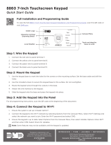
DEVICE SETUP
Advance to Device Setup, then press a select area to enter
the setup menu.
Device Number
Set the keypad address from 1-8 for XT30INT, and XR150INT
Series panels, or 1-16 for XR550INT Series panels.
Device Name
Enter a name for the device.
DEVICE SETUP
DEVICE SETUP
DEVICE NO: -
DEVICE SETUP
*UNUSED*

7800INT Series International Installation and Programming Guide | Digital Monitoring Products, Inc. 15
Device Type
For use as a standard keypad, select KPD. For use as an access
control keypad, press any select area, then select DOOR.
Communication Type (Door)
Ensure the COMM TYPE is set to KPD (Keypad Bus).
DEVICE SETUP
TYPE: KEYPAD
DEVICE SETUP
COMM TYPE: KPD
Configure additional options as needed. To configure custom card options for the keypad,
do not program CARD OPTIONS in Device Setup.

Digital Monitoring Products, Inc | 7800INT Series International Installation and Programming Guide 16
PROGRAM THE KEYPAD
Refer to the appropriate panel programming guide as needed. Keep in mind that
operation for some programming options is restricted to the appropriate model. Access
the Keypad Diagnostics menu by pressing Options in the carousel menu. Press the
Installer Options or wrench icon and enter 3577 (INST) and CMD for XR International
Series panels or enter 357 and CMD for XT30INT panels.
KEYPAD OPTIONS
To program keypad options, press the select area under
KPD OPT.
Current Keypad Address
Set the current keypad address from 01 to 08 for XT30INT
or XR150INT Series panels. Set the address from 01 to 16 for
XR550INT Series panels. The default address is set at 1. To
change the current address, press any select area to clear the
keypad display, enter the new address, and press CMD. It’s
not necessary to enter a leading zero for addresses 01 to 09.
KPD KPD
OPT DIAG STOP
CURRENT KEYPAD
ADDRESS: 1
/