Page is loading ...

Installation Instructions
PowerFlex
®
700S and 700H Frame 13
Replacement Power Structures
Introduction
Use this document to install a replacement power structure on a PowerFlex
700S or 700H frame 13 drive. This document covers the following
replacement power structures:
What You Need to Do
❐ Step 1: Remove power from the drive
❐ Step 2: Remove the old power structure
❐ Step 3: Install the new power structure
❐ Step 4: Connect the new power structure to the components in the
drive
❐ Step 5: Install the product identification label on the new power
structure
❐ Step 6: Start the drive
Voltage Class
Spare Module Catalog
String
PowerFlex
700H AC Input
PowerFlex
700H DC Input
PowerFlex
700S AC Input
PowerFlex
700S DC Input
400/480V AC
(540/650V DC)
SK-H1-PWRMOD-D1K1 20CC1K1 20CH1K1 20DC1K1 20DH1K1
20CD1K1 20CJ1K1 20DD1K1 20DJ1K1
SK-H1-PWRMOD-D1K3 20CC1K3 20CH1K3 20DC1K3 20DH1K3
20CD1K3 20CJ1K3 20DD1K3 20DJ1K3
SK-H1-PWRMOD-D1K4 20CC1K4 20CH1K4 20DC1K4 20DH1K4
20CD1K4 20CJ1K4 20DD1K4 20DJ1K4
600/690V AC
(810/932V DC)
SK-H1-PWRMOD-E920 20CE920 20CK920 20DE920 20DK920
20CF920 20CM920 20DF920 20DM920
SK-H1-PWRMOD-E1K0 20CE1K0 20CK1K0 20DE1K0 20DK1K0
20CF1K0 20CM1K0 20DF1K0 20DM1K0
SK-H1-PWRMOD-E1K1 20CE1K1 20CK1K1 20DE1K1 20DK1K1
20CF1K1 20CM1K1 20DF1K1 20DM1K1

2 PowerFlex® 700S and 700H Frame 13 Replacement Power Structures
Step 1: Removing Power
From the Drive
1. Turn off and lock out input power. Wait five minutes.
2. Verify that there is no voltage at the drive’s input power terminals.
3. Measure between the +DC and -DC terminals, between the +DC
terminal and the chassis, and between the -DC terminal and the chassis.
The voltage must be zero for all three measurements.
!
ATTENTION: To avoid an electric shock hazard, verify that
the voltage on the bus capacitors has discharged before servicing
the drive. Check the DC bus voltage at the Power Terminal
Block by measuring between the +DC and -DC terminals,
between the +DC terminal and the chassis, and between the -DC
terminal and the chassis. The voltage must be zero for all three
measurements.
Remove power before making or breaking cable connections.
When you remove or insert a cable connector with power
applied, an electrical arc may occur. An electrical arc can cause
personal injury or property damage by:
• sending an erroneous signal to your system’s field devices,
causing unintended machine motion
• causing an explosion in a hazardous environment
Electrical arcing causes excessive wear to contacts on both the
module and its mating connector. Worn contacts may create
electrical resistance.
L1 L2 L3
O
I

PowerFlex® 700S and 700H Frame 13 Replacement Power Structures 3
Step 2: Removing the Old
Power Structure
Before you can remove the old power structure from the drive, you must
remove the protective screens, protective covers and air flow plate from the
drive.
Removing the Protective Screens and Covers
1. For NEMA/UL Type 1 enclosures, remove the screws that secure the
protective screens to the enclosure and remove the screens.
2. Remove the four M5 POZIDRIV screws that secure each of the three
protective covers to the power structure and remove the protective
covers.
DC BUS CONDUCT
ORS AND CAPACITORS
OPERATE AT HIGH
VOLTAGE. REMO
VE POWER
AND W
AIT 5 MINUTES BEFORE SERVICING
DAN
GER
!
1
Three covers
2

4 PowerFlex® 700S and 700H Frame 13 Replacement Power Structures
Removing the Air Flow Plate
3. Remove the four T8 Torx-head screws that secure the airflow plate to
the drive.
4. Slide the airflow plate off of the drive.
3
4

PowerFlex® 700S and 700H Frame 13 Replacement Power Structures 5
Important:Before removing connections and wires, mark the connections
and wires to avoid incorrect wiring during assembly.
5. Remove the motor wiring from the output power terminals on the power
structure.
6. Remove the ground connection from the lower right corner of the power
structure.
7. Remove the input connections from the incoming DC bus terminals at
the top of the power structure.
DC-
DC+
DC-
DC+
DC-
DC+
U/T1 V/T2 W/T3
U/T1
V/T2 W/T3
Output Power Terminals
DC Bus Terminals
ASIC Board
Assembly
Power Supply Voltage
Feedback Board Assembly
Ground Terminals

6 PowerFlex® 700S and 700H Frame 13 Replacement Power Structures
8. Remove the four screws that secure the cover to the ASIC assembly and
remove the -DC bus connection from the cover.
9. Unplug the cooling fan that mounts to the ASIC assembly cover from
connector X1 on the ASIC board and remove the ASIC assembly cover.
=
Remove -DC bus
connection.

PowerFlex® 700S and 700H Frame 13 Replacement Power Structures 7
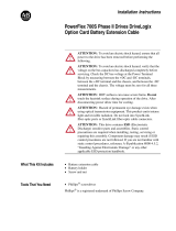
10. Disconnect the fiber optic cables (H1 - H7) from the ASIC board.
11. For drives with 700H control, disconnect the +24V supply cable from
connector X10 on ASIC board #1.
12. For drives with DC input, disconnect the external precharge circuitry
from connectors X9 and X15 from the ASIC board.
H11H12H13
H8
H9H10
X9
X15
X3X4X5
H4H5H6 H1H2H3
H7
X2
X10
X1
Disconnect fiber optic
cables (H1 - H7)
DC precharge
connections
Disconnect
cables

8 PowerFlex® 700S and 700H Frame 13 Replacement Power Structures
13. Pull the rubber grommet, through which the ASIC board and Power
Supply Voltage Feedback board wire bundles are routed, out of the
drive frame and secure the wire bundles in the left-hand enclosure of the
drive.
14. For drives with AC input, disconnect the precharge cable from the
Rectifying modules and the fan control cables, located in the power
structure to the left of the ASIC board.
Rubber grommet and
wire bundles.
Important: Move wire
bundles to left-hand
enclosure.
Fan control cables.
Shown disconnected.
Precharge cables.
Shown disconnected.

PowerFlex® 700S and 700H Frame 13 Replacement Power Structures 9
15. For drives with 700H control, continue with step 19 on page 11. For
drives with 700S control, disconnect the DC bus connection cable from
the connector J2 and the motor feedback connection cable from
connector J1 at the top of each the Power Supply Voltage Feedback
boards (see illustration below for location).
16. Carefully disconnect the fiber-optic cables from sockets J4 and J5 on
the side of each of the Power Supply Voltage Feedback boards and
carefully set them aside (see illustration below for location).
Important:Minimum inside bend radius for fiber-optic cable is 25.4 mm (1
in.). Any bends with a shorter inside radius can permanently
damage the fiber-optic cable. Signal attenuation increases with
decreased inside bend radii.
!
ATTENTION: Hazard of permanent eye damage exists when
using optical transmission equipment. This product emits intense
light and invisible radiation. Do not look into fiber-optic ports or
fiber-optic cable connectors.
J2
J1
J4
J5
Disconnect:

10 PowerFlex® 700S and 700H Frame 13 Replacement Power Structures
17. Remove the four screws that secure each of the Power Supply Voltage
Feedback board assemblies to the fan housing on the power structures
and carefully remove the Power Supply Voltage Feedback board
assemblies.
18. Disconnect the cable from connector J8 on each of the Power Supply
Voltage Feedback boards, and set the cable aside.
Remove screws
J2 J1
J4 J5
J8
Disconnect cable

PowerFlex® 700S and 700H Frame 13 Replacement Power Structures 11
19. Remove the two hexagonal screws that secure the power structure to the
enclosure frame.
20. Follow the instructions in publication PFLEX-IN014…, Installation
Instructions - PowerFlex 700S / 700H High Power Maintenance Stand,
to install the Maintenance Stand (part number 20-MAINSTND).
Remove the power structure by sliding it onto the rails of the
Maintenance Stand.
Note: The Maintenance Stand is designed for removing power
structures from drives supplied in Rittal TS8 enclosures. Alternate
means of removal will be necessary for other types of enclosures.
21. Follow the instructions in publication PFLEX-IN005…, Installation
Instructions - Lifting & Mounting PowerFlex 700S and 700H Drives
(Frame 10 - 14), supplied with the new power structure, to lift the power
structure off of the Maintenance Stand.
Step 3: Installing the New
Power Structure
Install the new power structure in reverse order of removal. Refer to the
publication PFLEX-IN006…, Installation Instructions - PowerFlex 700S
and 700H High Power Drives, for tightening torques of power and motor
terminations.
Remove screws - one each side of enclosure

12 PowerFlex® 700S and 700H Frame 13 Replacement Power Structures
Step 4: Connecting the
Power Structure to
Components in the Drive
1. For drives with AC input, connect the precharge cable and remove the
jumper from the fan control connector and connect the fan control cable
from the Rectifying modules to the Power Structure.
2. Use the tables and illustrations below to make all connections between
the ASIC, Power Supply Voltage Feedback and Fiber Optic Interface
(700S) or Fiber Optic Adapter (700H) and Common Mode Filter circuit
boards for your installation.
– Refer to PowerFlex 700S Phase II Drive Connections:
on page 15 for
a PowerFlex 700S circuit board connection diagram.
– Refer to PowerFlex 700H Connections:
on page 16 for a PowerFlex
700H circuit board connection diagram.
Important:If the drive has DC input, you must also connect the
precharge circuit. Refer to Pre-Charge Connections on
Drives with DC Input on page 18.
=
Connect fan control
cables
Connect Precharge
cables

PowerFlex® 700S and 700H Frame 13 Replacement Power Structures 13
Figure 1 Termination Points on the ASIC Board
Figure 2 Termination Points on the Power Supply Voltage Feedback Board
Connect to Pre-charge
circuitry on DC Input drives
Fiber Optic Connections to
Fiber Optic Interface Board
H11H12H13
H8
H9H10
X9
X15
X3X4X5
H4H5H6 H1H2H3
H7
X2
X10
X1
J2 J1
J4 J5
J8
Fiber Optic Connections to
Fiber Optic Interface Board

14 PowerFlex® 700S and 700H Frame 13 Replacement Power Structures
Figure 3 Termination Points on the 700S Fiber Optic Interface Board
Figure 4 Termination Points on the 700H Fiber Optic Adapter Board
J8
J10
J12
J6
J9
J11
J14
J7
J13
Fiber Optic Connections
to ASIC Board
H1
H2
H3
H4
H5
H6
H7
Fiber Optic Connections
to ASIC Board

PowerFlex® 700S and 700H Frame 13 Replacement Power Structures 15
Figure 5 Termination Points on the Common Mode Filter Board
PowerFlex 700S Phase II Drive Connections:
Figure 6 Connections Between the Power Structure and the 700S Phase II Control
J5
J1
Connect to J5 on Fiber Optic
Interface Board
From Connector J8 on Power
Supply Voltage Feedback Board
HIM
J1
2
9
20
10
J2
-U
-V
-W
DC-
DC+
J8
+24V
J4 Tx
J5 Rx
X3 J3
J2
J1
X2
X1
HIM
DOOR
EXTERNAL DPI
X4
2
PWR
STS
PORT
MOD
NET A
NET B
DPI Assembly
EXAMPLE:
20-HIM-A3
20-VB00601
M6
J17
J18
J15
External
24V DC
1 = 24V
3 = Common
(75W min)
J5
J6 Tx
J7 Rx
J4
2
2
+24 V Iso
+12 V
-12 V
+5V
Pan Fan
Control
J16
Fiber Optic
Interface
Board
80W
Power
Supply
Power Supply
Voltage
Feedback
DPI
Interface
Board
DPI
Comm
Option
DPI
Bezel
Fiber Optic Cables
J8 J9 J10 J11 J12 J14 J13
M
Fiber
8
9
9
ASIC Board
H1 (Gate Enable)
H2 (U Gate)
H3 (V Gate)
H4 (W Gate)
H5 (ADconv)
H6 (Vbus Tx)
H7 (Vbus Rx)
X10
J3
40
J2
30
J1
8
Inside Power Structure
Make and verify these connections
700S Control Assembly (Phase II)
J5
J1
2
Common Mode Filter Board
To 700S Main
Control Board

16 PowerFlex® 700S and 700H Frame 13 Replacement Power Structures
ASIC Board Connections
Power Supply Voltage Feedback Board Connections
PowerFlex 700H Connections:
Connect this component:
termination point … to this component : termination point
ASIC Board: H1 (fiber optic connector) Fiber Optic Interface Board: J8 (fiber optic connector)
ASIC Board: H2 (fiber optic connector) Fiber Optic Interface Board: J9 (fiber optic connector)
ASIC Board: H3 (fiber optic connector) Fiber Optic Interface Board: J10 (fiber optic connector)
ASIC Board: H4 (fiber optic connector) Fiber Optic Interface Board: J11 (fiber optic connector)
ASIC Board: H5 (fiber optic connector) Fiber Optic Interface Board: J12 (fiber optic connector)
ASIC Board: H6 (fiber optic connector) Fiber Optic Interface Board: J14 (fiber optic connector)
ASIC Board: H7 (fiber optic connector) Fiber Optic Interface Board: J13 (fiber optic connector)
ASIC Board: X10 Insulate and do not connect
Connect this component:
termination point …
to this component : termination
point
Power Supply Voltage Feedback Board: J8 Common Mode Filter Board: J5
Power Supply Voltage Feedback Board: J5 (fiber optic
connector)
Fiber Optic Interface Board: J6
Power Supply Voltage Feedback Board: J4 (fiber optic
connector)
Fiber Optic Interface Board: J7
Fiber Optic Adapter Board
ASIC
Board
X10
H1
H2
H3
H4
H5
H6
H7
Fiber Optic Cables
H1 H2 H3 H4 H5 H6 H7
X3
DPI
COMM
(Option)
X2
X4
DPI
Interface
X1
20
J2
HIM
Bezel
J1
HIM
X3
J3
HIM
DPI Assembly
PWR
STS
PORT
MOD
NET A
NET B
700H Control Assembly
Inside Power Structure
Make and verify these connections
+24V
Common
1
2
X2
X1
37
X2
(Slot A)
20C-DA1-A
(24V dc Digital Input
w/ Analog I/O)
or
20C-DA1-B
(115V ac Digital Input
w/ Analog I/O)
10
Analog
I/O
8 / 10
Digital
Inputs
X3
(Slot B)
20C-DO1
(Digital Output
Option)
3
Digital
Outputs
3
Digital
Outputs
X4
(Slot C)
Option
Board
X5
(Slot D)
Option
Board
X6
(Slot E)
20C-DPI1
(DPI Communications
Option)
X1
X3 X2
X7
(RS-232
Programming
Port)
X1
700H Control Board

PowerFlex® 700S and 700H Frame 13 Replacement Power Structures 17
ASIC Board Connections
Connect this component:
termination point … to this component : termination point
ASIC Board: H1 (fiber optic connector) Fiber Optic Adapter Board: H1 (fiber optic connector)
ASIC Board: H2 (fiber optic connector) Fiber Optic Adapter Board: H2 (fiber optic connector)
ASIC Board: H3 (fiber optic connector) Fiber Optic Adapter Board: H3 (fiber optic connector)
ASIC Board: H4 (fiber optic connector) Fiber Optic Adapter Board: H4 (fiber optic connector)
ASIC Board: H5 (fiber optic connector) Fiber Optic Adapter Board: H5 (fiber optic connector)
ASIC Board: H6 (fiber optic connector) Fiber Optic Adapter Board: H6 (fiber optic connector)
ASIC Board: H7 (fiber optic connector) Fiber Optic Adapter Board: H7 (fiber optic connector)
ASIC Board: X10 Fiber Optic Adapter Board: X2

18 PowerFlex® 700S and 700H Frame 13 Replacement Power Structures
Pre-Charge Connections on Drives with DC Input
You must connect the ASIC board connectors X9 and X15 to the X50
terminal block for the pre-charge circuit. The X50 terminal block is located
on the Control Frame in the left-hand enclosure. Refer to Figure 7 on
page 18 for the location of these connection points. Refer to publication
PFLEX-IN006…, Installation Instructions - PowerFlex 700S and 700H
Frame 9-14 Drives, for more information regarding the pre-charge circuit.
X50 Terminal Block Connections
Figure 7 Sample Pre-charge Wiring Diagram
ASIC Board Charge Relay Contact Ratings
ASIC Board
Connector Terminal to X50 Terminal Pre-Charge Circuit Connection Description
X9 25 . . . 1 Pre-charge Complete Signal (+24V DC)
26 . . . 2 Pre-charge Complete Signal (Common)
X15 21 . . . 3 Charge Relay Contact
23 . . . 4 Charge Relay Contact
M
F2 R2 CR2
DC+
DC Source
DC-
CR2R1F1
M
ASIC
Board
X9
X15
Precharge
Complete
25
26
21
22
23
CR1
M
CR2
M
CR1
2
X50
1
M
4
3
Charge
Relay*
* Refer to the “ASIC
Board Charge Relay
Contact Ratings” table
below.
External precharge circuitry is shown as dashed lines.
Load Resistance load (cos φ = 1)
Rated load 8 A at 250 VAC: 5 A at 30 VDC
Rated carry current 8 A
Max. switching voltage 250 VAC; 30 VDC, (400 VAC)
Max. switching current AC 8 A; DC 5 A
Max. switching power 2,000 VA; 150 W
Failure rate (reference value) 5 VDC 10 mA (for gold plating 0.35 µ min.)

PowerFlex® 700S and 700H Frame 13 Replacement Power Structures 19
Step 5: Installing the
Product Identification Label
on New Power Structure
All frame 13 replacement power structures are shipped from the factory
without a product identification label on the drive. If you are installing the
power structures in a 700S drive, you should label it with the accompanying
PowerFlex 700S label. If you are installing the power structures in a 700H
drive, you should label it with the accompanying PowerFlex 700H label.
Step 6: Starting the Drive
1. Install the protective covers and screens and the air flow plate on the
drive. Installation is in the reverse order of removal as indicated in Step
3: Removing the Old Power Structure
on page 3.
2. Start up the drive. Refer to the Start Up procedures in the appropriate
publication:
– User Manual - PowerFlex 700S Drives with Phase II Control,
20D-UM006…
– Programming Manual - PowerFlex 700H Drives, 20C-PM001…
DC BUS CONDUCT
ORS AND CAP
A
CITORS
OPERA
TE AT HIGH
VOL
TAGE. REMO
VE PO
W
ER
AND W
AIT 5 MINUTES BEFOR
E SER
VICING
DANGER
!
OR

www.rockwellautomation.com
A
mericas: Rockwell Automation, 1201 South Second Street, Milwaukee, WI 53204-2496 USA, Tel: (1) 414.382.2000, Fax: (1) 414.382.4444
Europe/Middle East/Africa: Rockwell Automation, Vorstlaan/Boulevard du Souverain 36, 1170 Brussels, Belgium, Tel: (32) 2 663 0600, Fax: (32) 2 663 0640
A
sia Pacific: Rockwell Automation, Level 14, Core F, Cyberport 3, 100 Cyberport Road, Hong Kong, Tel: (852) 2887 4788, Fax: (852) 2508 1846
Power, Control and Information Solutions Headquarters
Publication PFLEX-IN013B-EN-P - August 2008 20 360407-P02
Supersedes PFLEX-IN013A-EN-P - April 2006 Copyright © 2008 Rockwell Automation. All rights reserved. Printed in the U.S.A.
Reference Materials
Allen-Bradley publications are available on the internet at
www.rockwellautomation.com/literature.
The following manuals are recommended for general drive information:
The following manuals are recommended for detailed PowerFlex 700S and
700H information:
For Allen-Bradley Drives Technical Support:
Title Publication
Wiring and Grounding Guidelines for Pulse Width Modulated
Drives
DRIVES-IN001…
Industrial Automation Wiring and Grounding Guidelines 1770-4.1
Preventive Maintenance of Industrial Control and Drive System
Equipment
DRIVES-TD001…
Safety Guidelines for the Application, Installation and Maintenance
of Solid State Control
SGI-1.1
A Global Reference Guide for Reading Schematic Diagrams 0100-2.10
Guarding Against Electrostatic Damage 8000-4.5.2
Title Publication
User Manual - PowerFlex 700S Drives with Phase II Control 20D-UM006…
Programming Manual - PowerFlex 700H Drives 20C-PM001…
Reference Manual - PowerFlex 700S Drives with Phase II Control PFLEX-RM003…
Installation Instructions - PowerFlex 700S and 700H Drives (Frames 9-14) PFLEX-IN006…
Installation Instructions - PowerFlex® 700S and 700H Drives Frames 10-14
Maintenance Stand
PFLEX-IN014…
Title Online at...
Allen-Bradley Drives Technical Support www.ab.com/support/abdrives
/