Page is loading ...

Adjustable Frequency AC Drive
Series A
Standard and Vector Control
Firmware Versions
Standard Control: xxx.x - 3.001
Vector Control: xxx.x - 3.002
User Manual
www.abpowerflex.com

Important User Information
Solid state equipment has operational characteristics differing from those of
electromechanical equipment. Safety Guidelines for the Application, Installation
and Maintenance of Solid State Controls (Publication SGI-1.1 available from your
local Rockwell Automation sales office or www.rockwellautomation.com/literature)
describes some important differences between solid state equipment and
hard-wired electromechanical devices. Because of this difference, and also because
of the wide variety of uses for solid state equipment, all persons responsible for
applying this equipment must satisfy themselves that each intended application of
this equipment is acceptable.
In no event will Rockwell Automation, Inc. be responsible or liable for indirect or
consequential damages resulting from the use or application of this equipment.
The examples and diagrams in this manual are included solely for illustrative
purposes. Because of the many variables and requirements associated with any
particular installation, Rockwell Automation, Inc. cannot assume responsibility or
liability for actual use based on the examples and diagrams.
No patent liability is assumed by Rockwell Automation, Inc. with respect to use of
information, circuits, equipment, or software described in this manual.
Reproduction of the contents of this manual, in whole or in part, without written
permission of Rockwell Automation, Inc. is prohibited.
Throughout this manual, when necessary we use notes to make you aware of safety
considerations.
Important: Identifies information that is critical for successful application and
understanding of the product.
DriveExplorer, DriveExecutive, Force Technology and SCANport are trademarks of Rockwell Automation, Inc.
PowerFlex and PLC are registered trademarks of Rockwell Automation, Inc.
ControlNet is a trademark of ControlNet International, Ltd.
DeviceNet is a trademark of the Open DeviceNet Vendor Association.
WARNING: Identifies information about practices or circumstances
that can cause an explosion in a hazardous environment, which may
lead to personal injury or death, property damage, or economic loss.
ATTENTION: Identifies information about practices or circumstances
that can lead to personal injury or death, property damage, or economic
loss. Attentions help you:
• identify a hazard
• avoid the hazard
• recognize the consequences
Shock Hazard labels may be located on or inside the equipment (e.g.,
drive or motor) to alert people that dangerous voltage may be present.
Burn Hazard labels may be located on or inside the equipment (e.g.,
drive or motor) to alert people that surfaces may be at dangerous
temperatures.

Document Update
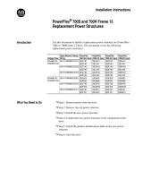
PowerFlex 700 User Manual Update
This document provides important information for the following
PowerFlex 700 User Manuals:
• Series A - publication 20B-UM001x-xx-x
• Series B - publication 20B-UM002x-xx-x
Included is new information about using the PowerFlex 700 drive with
an Auxiliary Control Power Supply (such as the 20-24V-AUX1). Place
this document with your User Manual for future reference.
Auxiliary Control Power Supply
An Auxiliary Control Power Supply can provide control power for
certain PowerFlex 700 drives. See details below.
The Auxiliary Control Power Supply Must Not be used with…
• Any Standard Control
drive (15
th
position of the catalog number
string equals “A,” “B,” or “N”).
• Any 200/240V
PowerFlex 700 drive, Standard or Vector Control
(4
th
position of the catalog number string equals “B”).
The Auxiliary Control Power Supply Can be used with…
• 400/480
and 600/690 Volt drives with Vector Control (15
th
position
of the catalog number string equals “C,” or “D”). Consult the factory
when using an auxiliary power supply in these instances.
Use of an auxiliary power supply to keep the drive control logic up
when the main AC power is removed requires the use of some type
of AC line monitoring as well as control of the Precharge Enable
signal. Consult the factory for additional guidance.
!
ATTENTION: The Auxiliary Control Power Supply Must Not be
used with any PowerFlex 700 Standard Control drive or 200/240 Volt
Vector Control drive. Using the power supply with these drives will
cause equipment/component damage.


Summary of Changes
The information below summarizes the changes to the PowerFlex 700
User Manual, publication 20B-UM001 since the last release.
Manual Updates
Change Page
Bypass Attention statement added P-3
Catalog Number Explanation updated P-4
Mounting section updated 1-2
Shield Termination description updated 1-4
Power Terminal Block Specifications updated 1-9
Recommended Signal Wire table updated 1-15
CE General Notes & Table 1.I updated 1-25
“Flashing, Drive Stopped” Status Indicator updated 2-2 & 4-2
[Dig Out Setpt] description updated 3-58
“Decel Inhibit” Action #3 updated 4-5
Sound Pressure specification added A-2
Motor Starter catalog numbers updated A-8 through A-12

soc-ii Summary of Changes
Notes:

Table of Contents
Preface Overview
Who Should Use this Manual? . . . . . . . . . P-1
What Is Not in this Manual . . . . . . . . . . . . P-1
Reference Materials . . . . . . . . . . . . . . . . . P-2
Manual Conventions . . . . . . . . . . . . . . . . . P-2
Drive Frame Sizes . . . . . . . . . . . . . . . . . . . P-3
General Precautions . . . . . . . . . . . . . . . . . P-3
Catalog Number Explanation . . . . . . . . . . P-4
Chapter 1 Installation/Wiring
Opening the Cover . . . . . . . . . . . . . . . . . . 1-1
Mounting Considerations . . . . . . . . . . . . . 1-2
AC Supply Source Considerations . . . . . . 1-2
General Grounding Requirements . . . . . . 1-4
Fuses and Circuit Breakers . . . . . . . . . . . . 1-5
Power Wiring . . . . . . . . . . . . . . . . . . . . . . 1-5
Using Input/Output Contactors . . . . . . . . 1-12
Disconnecting MOVs and CM Capacitors 1-13
I/O Wiring . . . . . . . . . . . . . . . . . . . . . . . . 1-15
Reference Control . . . . . . . . . . . . . . . . . . 1-22
Auto/Manual Examples. . . . . . . . . . . . . . 1-23
Lifting/Torque Proving . . . . . . . . . . . . . . 1-24
Common Bus/Precharge Notes . . . . . . . . 1-24
EMC Instructions . . . . . . . . . . . . . . . . . . 1-25
Chapter 2 Start Up
Prepare For Drive Start-Up . . . . . . . . . . . . 2-1
Status Indicators . . . . . . . . . . . . . . . . . . . . 2-2
Start-Up Routines . . . . . . . . . . . . . . . . . . . 2-3
Running S.M.A.R.T. Start. . . . . . . . . . . . . 2-4
Running an Assisted Start Up . . . . . . . . . . 2-4
Chapter 3 Programming
and Parameters
About Parameters . . . . . . . . . . . . . . . . . . . 3-1
How Parameters are Organized. . . . . . . . . 3-3
Monitor File . . . . . . . . . . . . . . . . . . . . . . 3-12
Motor Control File . . . . . . . . . . . . . . . . . 3-14
Speed Command File . . . . . . . . . . . . . . . 3-21
Dynamic Control File . . . . . . . . . . . . . . . 3-31
Utility File . . . . . . . . . . . . . . . . . . . . . . . . 3-38
Communication File . . . . . . . . . . . . . . . . 3-49
Inputs & Outputs File . . . . . . . . . . . . . . . 3-53
Applications File . . . . . . . . . . . . . . . . . . . 3-59
Parameter Cross Reference – by Name. . 3-61
Parameter Cross Reference – by Number 3-64
Chapter 4 Troubleshooting
Faults and Alarms . . . . . . . . . . . . . . . . . . . 4-1
Drive Status . . . . . . . . . . . . . . . . . . . . . . . . 4-2
Manually Clearing Faults . . . . . . . . . . . . . 4-4
Fault Descriptions . . . . . . . . . . . . . . . . . . . 4-4
Clearing Alarms . . . . . . . . . . . . . . . . . . . . 4-9
Alarm Descriptions . . . . . . . . . . . . . . . . . 4-10
Common Symptoms/Corrective Actions 4-13
Testpoint Codes and Functions . . . . . . . . 4-16
Appendices See Next Page

ii Table of Contents
Appendix A Supplemental Drive
Information
Specifications. . . . . . . . . . . . . . . . . . . . . . . A-1
Communication Configurations . . . . . . . . A-4
Output Devices . . . . . . . . . . . . . . . . . . . . . A-7
Drive, Fuse & Circuit Breaker Ratings . . . A-7
Dimensions . . . . . . . . . . . . . . . . . . . . . . . A-15
Frame Cross Reference . . . . . . . . . . . . . . A-22
Appendix B HIM Overview
External and Internal Connections . . . . . . B-1
LCD Display Elements . . . . . . . . . . . . . . . B-2
ALT Functions . . . . . . . . . . . . . . . . . . . . . . B-2
Menu Structure . . . . . . . . . . . . . . . . . . . . . B-3
Viewing and Editing Parameters . . . . . . . . B-5
Linking Parameters (Vector Option Only). B-6
Removing/Installing the HIM . . . . . . . . . . B-8
Appendix C Application Notes
External Brake Resistor . . . . . . . . . . . . . . . C-1
Lifting/Torque Proving . . . . . . . . . . . . . . . C-2
Minimum Speed . . . . . . . . . . . . . . . . . . . . C-7
Motor Control Technology . . . . . . . . . . . . C-8
Motor Overload . . . . . . . . . . . . . . . . . . . . C-10
Overspeed . . . . . . . . . . . . . . . . . . . . . . . . C-11
Power Loss Ride Through . . . . . . . . . . . . C-12
Process PI for Standard Control . . . . . . . C-13
Reverse Speed Limit . . . . . . . . . . . . . . . . C-16
Skip Frequency . . . . . . . . . . . . . . . . . . . . C-17
Sleep Wake Mode . . . . . . . . . . . . . . . . . . C-19
Start At PowerUp. . . . . . . . . . . . . . . . . . . C-21
Stop Mode . . . . . . . . . . . . . . . . . . . . . . . . C-22
Voltage Tolerance . . . . . . . . . . . . . . . . . . C-24
Index

Preface
Overview
The purpose of this manual is to provide you with the basic information
needed to install, start-up and troubleshoot the PowerFlex 700
Adjustable Frequency AC Drive.
This manual is intended for qualified personnel. You must be able to
program and operate Adjustable Frequency AC Drive devices. In
addition, you must have an understanding of the parameter settings and
functions.
The PowerFlex 700 User Manual is designed to provide only basic
start-up information. For detailed drive information, please refer to the
PowerFlex Reference Manual. The reference manual is included on the
CD supplied with your drive or is also available online at
http://www.rockwellautomation.com/literature.
For information on . . . See page . . .
Who Should Use this Manual?
P-1
What Is Not in this Manual P-1
Reference Materials P-2
Manual Conventions P-2
Drive Frame Sizes P-3
General Precautions P-3
Catalog Number Explanation P-4
Who Should Use this Manual?
What Is Not in this Manual

P-2 Overview
The following manuals are recommended for general drive information:
For detailed PowerFlex 700 information:
For Allen-Bradley Drives Technical Support:
• In this manual we refer to the PowerFlex 700 Adjustable Frequency
AC Drive as; drive, PowerFlex 700 or PowerFlex 700 Drive.
• To help differentiate parameter names and LCD display text from
other text, the following conventions will be used:
– Parameter Names will appear in [brackets].
For example: [DC Bus Voltage].
– Display Text will appear in “quotes.” For example: “Enabled.”
• The following words are used throughout the manual to describe an
action:
Reference Materials
Title Publication Available Online at . . .
Wiring and Grounding Guidelines
for PWM AC Drives
DRIVES-IN001…
www.rockwellautomation.com/
literature
Preventive Maintenance of
Industrial Control and Drive
System Equipment
DRIVES-TD001…
Safety Guidelines for the
Application, Installation and
Maintenance of Solid State Control
SGI-1.1
A Global Reference Guide for
Reading Schematic Diagrams
100-2.10
Guarding Against Electrostatic
Damage
8000-4.5.2
Title Publication Available . . .
PowerFlex
Reference Manual
PFLEX-RM001… on the CD supplied with the drive or
www.rockwellautomation.com/literature
Title Online at . . .
Allen-Bradley Drives Technical Support www.ab.com/support/abdrives
Manual Conventions
Word Meaning
Can Possible, able to do something
Cannot Not possible, not able to do something
May Permitted, allowed
Must Unavoidable, you must do this
Shall Required and necessary
Should Recommended
Should Not Not recommended

Overview P-3
Similar PowerFlex 700 drive sizes are grouped into frame sizes to
simplify spare parts ordering, dimensioning, etc. A cross reference of
drive catalog numbers and their respective frame size is provided in
Appendix
A.
Drive Frame Sizes
General Precautions
!
ATTENTION: This drive contains ESD (Electrostatic Discharge)
sensitive parts and assemblies. Static control precautions are required
when installing, testing, servicing or repairing this assembly.
Component damage may result if ESD control procedures are not
followed. If you are not familiar with static control procedures,
reference A-B publication 8000-4.5.2, “Guarding Against Electrostatic
Damage” or any other applicable ESD protection handbook.
!
ATTENTION: An incorrectly applied or installed drive can result in
component damage or a reduction in product life. Wiring or application
errors, such as, undersizing the motor, incorrect or inadequate AC
supply, or excessive ambient temperatures may result in malfunction of
the system.
!
ATTENTION: Only qualified personnel familiar with adjustable
frequency AC drives and associated machinery should plan or
implement the installation, start-up and subsequent maintenance of the
system. Failure to comply may result in personal injury and/or
equipment damage.
!
ATTENTION: To avoid an electric shock hazard, verify that the
voltage on the bus capacitors has discharged before performing any
work on the drive. Measure the DC bus voltage at the +DC & –DC
terminals of the Power Terminal Block (refer to Chapter
1 for location).
The voltage must be zero.
!
ATTENTION: Risk of injury or equipment damage exists. DPI or
SCANport host products must not be directly connected together via
1202 cables. Unpredictable behavior can result if two or more devices
are connected in this manner.
!
ATTENTION: An incorrectly applied or installed bypass system can
result in component damage or reduction in product life. The most
common causes are:
• Wiring AC line to drive output or control terminals.
• Improper bypass or output circuits not approved by Allen-Bradley.
• Output circuits which do not connect directly to the motor.
Contact Allen-Bradley for assistance with application or wiring.

P-4 Overview
The PowerFlex 700 catalog numbering scheme is shown on page P-5
.
!
ATTENTION: The “adjust freq” portion of the bus regulator function
is extremely useful for preventing nuisance overvoltage faults resulting
from aggressive decelerations, overhauling loads, and eccentric loads. It
forces the output frequency to be greater than commanded frequency
while the drive's bus voltage is increasing towards levels that would
otherwise cause a fault. However, it can also cause either of the
following two conditions to occur.
1. Fast positive changes in input voltage (more than a 10% increase
within 6 minutes) can cause uncommanded positive speed changes.
However an “OverSpeed Limit” fault will occur if the speed reaches
[Max Speed] + [Overspeed Limit]. If this condition is unacceptable,
action should be taken to 1) limit supply voltages within the
specification of the drive and, 2) limit fast positive input voltage
changes to less than 10%. Without taking such actions, if this
operation is unacceptable, the “adjust freq” portion of the bus
regulator function must be disabled (see parameters 161 and 162).
2. Actual deceleration times can be longer than commanded
deceleration times. However, a “Decel Inhibit” fault is generated if
the drive stops decelerating altogether. If this condition is
unacceptable, the “adjust freq” portion of the bus regulator must be
disabled (see parameters 161 and 162). In addition, installing a
properly sized dynamic brake resistor will provide equal or better
performance in most cases.
Important: These faults are not instantaneous. Test results have
shown that they can take between 2-12 seconds to
occur.
!
ATTENTION: Loss of control in suspended load applications can
cause personal injury and/or equipment damage. Loads must always be
controlled by the drive or a mechanical brake. Parameters 600-611 are
designed for lifting/torque proving applications. It is the responsibility
of the engineer and/or end user to configure drive parameters, test any
lifting functionality and meet safety requirements in accordance with all
applicable codes and standards.
Catalog Number Explanation

Overview P-5
Code Vol t ag e Ph. Prechg.
B240V AC3–
C400V AC3–
D480V AC3–
E600V AC
➌
3–
F690V AC3–
H540V DC
➍
–N
J650V DC
➍
–N
P540V DC
➍
–Y
R650V DC
➍
–Y
Code
Control I/O Volts
A Std. 24V DC/AC
B Std. 115V AC
CVector
➎
24V DC/AC
DVector
➎
115V AC
NStd. None
Code
Version
C ControlNet (Coax)
D DeviceNet
E EtherNet/IP
RRIO
S RS-485
NNone
Code
Operator Interface
0Blank Cover
2 Digital LCD
3 Full Numeric LCD
4 Analog LCD
5 Prog. Only LCD
Code
w/Resistor
YYes
➊
NNo
Code
CE Filter CM Choke
AYes Yes
BYes No
Code
Type
0None
1 Encoder, 12V
Code
Enclosure
AIP 20,
NEMA Type 1
NOpen
Code
w/Brake IGBT
➋
YYes
NNo
➊ Not available for Frame 3 drives or larger.
➋ Brake IGBT is standard on Frames 0-3 and optional on Frames 4-6.
➌ Note: CE Certification testing has not been performed on 600V class drives.
➍ Frames 5 & 6 Only.
➎ Vector Control Option utilizes DPI Only.
➏ Must be used with Vector Control option C or D (position 15). Positions 17-20 are only
required when custom firmware is supplied.
➐ Positions 16-20 of the catalog number are not applicable for Canada. These options
(positions 16-20) are only available as User Installed in Canada
Code Type
A User Manual
N No Manual
Code Type
20B 700
400V 60Hz Input
400V
Code
Amps kW
1P3 1.3 0.37
2P1 2.1 0.75
3P5 3.5 1.5
5P0 5.0 2.2
8P7 8.7 4.0
011 11.5 5.5
015 15.4 7.5
022 22 11
030 30 15
037 37 18.5
043 43 22
056 56 30
072 72 37
085 85 45
105 105 55
125 125 55
140 140 75
170 170 90
205 205 110
260 260 132
600V 60Hz Input
➌
600V
Code
Amps HP
1P7 1.7 1.0
2P7 2.7 2.0
3P9 3.9 3.0
6P1 6.1 5.0
9P0 9.0 7.5
011 11 10
017 17 15
022 22 20
027 27 25
032 32 30
041 41 40
052 52 50
062 62 60
077 77 75
099 99 100
125 125 125
144 144 150
208/240V 60Hz Input
208V 240V
Code
Amps Amps HP
2P2 2.5 2.2 0.5
4P2 4.8 4.2 1.0
6P8 7.8 6.8 2.0
9P6 11 9.6 3.0
015 17.5 15.3 5.0
022 25.3 22 7.5
028 32.2 28 10
042 48.3 42 15
052 56 52 20
070 78.2 70 25
080 92 80 30
104 120 104 40
130 130 130 50
154 177 154 60
192 221 192 75
690V 60Hz Input
690V
Code
Amps kW
052 52 45
060 60 55
082 82 75
098 98 90
119 119 110
142 142 132
480V 60Hz Input
480V
Code
Amps HP)
1P1 1.1 0.5
2P1 2.1 1.0
3P4 3.4 2.0
5P0 5.0 3.0
8P0 8.0 5.0
011 11 7.5
014 14 10
022 22 15
027 27 20
034 34 25
040 40 30
052 52 40
065 65 50
077 77 60
096 96 75
125 125 100
156 156 125
180 180 150
248 248 200
Code Type
AD➏ 60Hz Maximum
Position
1-3 4 5-7 8 9 10 11 12 13 14 15 16 ➐ 17-18➐ 19-20➐
20B D 2P1 A 3 A Y N A R C 0 NN AD
Drive Voltage Rating Rating Enclosure HIM Documentation Brake Brake Resistor Emission Comm Slot I/O Feedback Future
Use
Custom
Firmware

P-6 Overview
Notes:

Chapter 1
Installation/Wiring
This chapter provides information on mounting and wiring the
PowerFlex 700 Drive.
Most start-up difficulties are the result of incorrect wiring. Every
precaution must be taken to assure that the wiring is done as instructed.
All items must be read and understood before the actual installation
begins.
For information on . . See page For information on. . See page
Opening the Cover
1-1 Disconnecting MOVs and
Common Mode Capacitors
1-13
Mounting Considerations 1-2
AC Supply Source Considerations 1-2 I/O Wiring 1-15
General Grounding Requirements 1-4 Reference Control 1-22
Fuses and Circuit Breakers 1-5 Auto/Manual Examples 1-23
Power Wiring 1-5 Lifting/Torque Proving 1-24
EMC Instructions 1-25
!
ATTENTION: The following information is merely a guide for proper
installation. The Allen-Bradley Company cannot assume responsibility
for the compliance or the noncompliance to any code, national, local or
otherwise for the proper installation of this drive or associated
equipment. A hazard of personal injury and/or equipment damage
exists if codes are ignored during installation.
Opening the Cover
Esc
7 8 9
4 5 6
1 2 3
.
0 +/-
Sel
Jog
Alt
POWER
STS
PORT
MOD
NET A
NET B
Exp
Param #
S
.M
.A
.R
.T
.
E
x
it
L
a
n
g
A
u
t
o
/ M
a
n
R
e
m
o
v
e
HOT surfaces can cause severe burns
CAUTION
Frames 0-4
Locate the slot in the upper left corner.
Slide the locking tab up and swing the
cover open. Special hinges allow cover to
move away from drive and lay on top of
adjacent drive (if present). See page 1-7
for frame 4 access panel removal.
Frame 5
Slide the locking tab up, loosen the
right-hand cover screw and remove. See
page 1-7
for access panel removal.
Frame 6
Loosen 2 screws at bottom of drive cover.
Carefully slide bottom cover down & out.
Loosen the 2 screws at top of cover and
remove.

1-2 Installation/Wiring
Operating Temperatures
PowerFlex 700 drives are designed to operate at 0° to 40° C ambient.
To operate the drive in installations between 41° and 50° C, see below.
Table 1.A Acceptable Surrounding Air Temperature & Required Actions
Minimum Mounting Clearances
Specified vertical clearance requirements are intended to be from drive
to drive. Other objects can occupy this space; however, reduced airflow
may cause protection circuits to fault the drive. In addition, inlet air
temperature must not exceed the product specification.
PowerFlex 700 drives are suitable for use on a circuit capable of
delivering up to a maximum of 200,000 rms symmetrical amperes, and a
maximum of 600 volts.
Mounting Considerations
Drive Catalog
Number
Required Action . . .
IP 20, NEMA Type 1
(1)
IP 20, NEMA Type Open IP 00, NEMA Type Open
No Action Required Remove Top Label
(2)
Remove Top Label & Vent Plate
(3)
All Except 20BC072 40° C50° CNA
20BC072 40° C45° C50° C
(1)
IP20 (NEMA Type 1) general purpose enclosures are intended for indoor use primarily to provide a
degree of protection against contact with enclosed equipment. These enclosures offer no
protection against airborne contaminants such as dust or water.
(2)
Removing the adhesive top label from the drive changes the NEMA enclosure rating from Type 1 to
Open type.
(3)
To remove vent plate (see page A-20 for location), lift top edge of plate from the chassis. Rotate
the plate out from the back plate.
101.6 mm
(4.0 in.)
101.6 mm
(4.0 in.)
50.8 mm
(2.0 in.)
101.6 mm
(4.0 in.)
101.6 mm
(4.0 in.)
PWR
STS
PORT
MOD
NET A
NET B
PWR
STS
PORT
MOD
NET A
NET B
Refer to Appendix A for
detailed dimension
information.
No Adhesive Label
(see Table 1.A)
With Adhesive Label
(see Table 1.A)
101.6 mm
(4.0 in.)
101.6 mm
(4.0 in.)
101.6 mm
(4.0 in.)
101.6 mm
(4.0 in.)
PWR
STS
PORT
MOD
NET A
NET B
PWR
STS
PORT
MOD
NET A
NET B
AC Supply Source Considerations

Installation/Wiring 1-3
If a system ground fault monitor (RCD) is to be used, only Type B
(adjustable) devices should be used to avoid nuisance tripping.
Unbalanced or Ungrounded Distribution Systems
If phase to ground voltage will exceed 125% of normal line to line
voltage or the supply system is ungrounded, refer to the Wiring and
Grounding Guidelines for PWM AC Drives (publication
DRIVES-IN001).
Input Power Conditioning
Certain events on the power system supplying a drive can cause
component damage or shortened product life. These conditions are
divided into 2 basic categories:
1. All drives
– The power system has power factor correction capacitors
switched in and out of the system, either by the user or by the
power company.
– The power source has intermittent voltage spikes in excess of
6000 volts. These spikes could be caused by other equipment on
the line or by events such as lightning strikes.
– The power source has frequent interruptions.
2. 5 HP or Less Drives (in addition to “1
” above)
– The nearest supply transformer is larger than 100kVA or the
available short circuit (fault) current is greater than 100,000A.
– The impedance in front of the drive is less than 0.5%.
If any or all of these conditions exist, it is recommended that the user
install a minimum amount of impedance between the drive and the
source. This impedance could come from the supply transformer itself,
the cable between the transformer and drive or an additional transformer
or reactor. The impedance can be calculated using the information
supplied in Wiring and Grounding Guidelines for PWM AC Drives,
publication DRIVES-IN001.
!
ATTENTION: To guard against personal injury and/or equipment
damage caused by improper fusing or circuit breaker selection, use only
the recommended line fuses/circuit breakers specified in Appendix
A.
!
ATTENTION: PowerFlex 700 drives contain protective MOVs and
common mode capacitors that are referenced to ground. These devices
should be disconnected if the drive is installed on an ungrounded
distribution system. See page 1-13
for jumper locations.

1-4 Installation/Wiring
The drive Safety Ground - PE must be connected to system ground.
Ground impedance must conform to the requirements of national and
local industrial safety regulations and/or electrical codes. The integrity
of all ground connections should be periodically checked.
For installations within a cabinet, a single safety ground point or ground
bus bar connected directly to building steel should be used. All circuits
including the AC input ground conductor should be grounded
independently and directly to this point/bar.
Figure 1.1 Typical Grounding
Safety Ground - PE
This is the safety ground for the drive that is required by code. This point
must be connected to adjacent building steel (girder, joist), a floor
ground rod or bus bar (see above). Grounding points must comply with
national and local industrial safety regulations and/or electrical codes.
Shield Termination - SHLD
The Shield terminal (see Figure 1.3 on page 1-10) provides a grounding
point for the motor cable shield. The motor cable shield should be
connected to this terminal on the drive (drive end) and the motor frame
(motor end). A shield terminating cable gland may also be used.
When shielded cable is used for control and signal wiring, the shield
should be grounded at the source end only, not at the drive end.
RFI Filter Grounding
Using an optional RFI filter may result in relatively high ground leakage
currents. Therefore, the filter must only be used in installations with
grounded AC supply systems and be permanently installed and
solidly grounded (bonded) to the building power distribution ground.
Ensure that the incoming supply neutral is solidly connected (bonded) to
the same building power distribution ground. Grounding must not rely
on flexible cables and should not include any form of plug or socket that
would permit inadvertent disconnection. Some local codes may require
redundant ground connections. The integrity of all connections should be
periodically checked. Refer to the instructions supplied with the filter.
General Grounding Requirements
U (T1)
V (T2)
W (T3)
R (L1)
S (L2)
T (L3)
PE
SHLD

Installation/Wiring 1-5
The PowerFlex 700 can be installed with either input fuses or an input
circuit breaker. National and local industrial safety regulations and/or
electrical codes may determine additional requirements for these
installations. Refer to Appendix
A for recommended fuses/circuit
breakers.
Cable Types Acceptable for 200-600 Volt Installations
A variety of cable types are acceptable for drive installations. For many
installations, unshielded cable is adequate, provided it can be separated
from sensitive circuits. As an approximate guide, allow a spacing of 0.3
meters (1 foot) for every 10 meters (32.8 feet) of length. In all cases,
long parallel runs must be avoided. Do not use cable with an insulation
thickness less than or equal to 15 mils (0.4mm/0.015 in.). Use Copper
wire only. Wire gauge requirements and recommendations are based on
75 degrees C. Do not reduce wire gauge when using higher temperature
wire.
Unshielded
THHN, THWN or similar wire is acceptable for drive installation in dry
environments provided adequate free air space and/or conduit fill rates
limits are provided. Do not use THHN or similarly coated wire in wet
areas. Any wire chosen must have a minimum insulation thickness of 15
Mils and should not have large variations in insulation concentricity.
Fuses and Circuit Breakers
!
ATTENTION: The PowerFlex 700 does not provide branch short
circuit protection. Specifications for the recommended fuse or circuit
breaker to provide protection against short circuits are provided in
Appendix
A.
Power Wiring
!
ATTENTION: National Codes and standards (NEC, VDE, BSI etc.)
and local codes outline provisions for safely installing electrical
equipment. Installation must comply with specifications regarding wire
types, conductor sizes, branch circuit protection and disconnect
devices. Failure to do so may result in personal injury and/or equipment
damage.

1-6 Installation/Wiring
Shielded/Armored Cable
Shielded cable contains all of the general benefits of multi-conductor
cable with the added benefit of a copper braided shield that can contain
much of the noise generated by a typical AC Drive. Strong consideration
for shielded cable should be given in installations with sensitive
equipment such as weigh scales, capacitive proximity switches and other
devices that may be affected by electrical noise in the distribution
system. Applications with large numbers of drives in a similar location,
imposed EMC regulations or a high degree of communications/
networking are also good candidates for shielded cable.
Shielded cable may also help reduce shaft voltage and induced bearing
currents for some applications. In addition, the increased impedance of
shielded cable may help extend the distance that the motor can be
located from the drive without the addition of motor protective devices
such as terminator networks. Refer to Reflected Wave in “Wiring and
Grounding Guidelines for PWM AC Drives,” publication
DRIVES-IN001A-EN-P.
Consideration should be given to all of the general specifications
dictated by the environment of the installation, including temperature,
flexibility, moisture characteristics and chemical resistance. In addition,
a braided shield should be included and be specified by the cable
manufacturer as having coverage of at least 75%. An additional foil
shield can greatly improve noise containment.
A good example of recommended cable is Belden® 295xx (xx
determines gauge). This cable has four (4) XLPE insulated conductors
with a 100% coverage foil and an 85% coverage copper braided shield
(with drain wire) surrounded by a PVC jacket.
Other types of shielded cable are available, but the selection of these
types may limit the allowable cable length. Particularly, some of the
newer cables twist 4 conductors of THHN wire and wrap them tightly
with a foil shield. This construction can greatly increase the cable
charging current required and reduce the overall drive performance.
Unless specified in the individual distance tables as tested with the drive,
these cables are not recommended and their performance against the lead
length limits supplied is not known.
See Table 1.B
.
Table 1.B Recommended Shielded Wire
Location Rating/Type Description
Standard
(Option 1)
600V, 90°C (194°F)
XHHW2/RHW-2
Anixter B209500-B209507,
Belden 29501-29507, or
equivalent
• Four tinned copper conductors with XLPE insulation.
• Copper braid/aluminum foil combination shield and
tinned copper drain wire.
• PVC jacket.
/