Page is loading ...

PowerFlex SCR Bus Supply
Firmware Version 1.xxx
User Manual

PowerFlex SCR Bus Supply User Manual
Important User Information
Solid state equipment has operational characteristics differing from those of
electromechanical equipment. Safety Guidelines for the Application,
Installation and Maintenance of Solid State Controls (Publication SGI-1.1
available from your local Rockwell Automation sales office or online at
http://
www.rockwellautomation.com/literature) describes some important differences
between solid state equipment and hard-wired electromechanical devices.
Because of this difference, and also because of the wide variety of uses for solid
state equipment, all persons responsible for applying this equipment must
satisfy themselves that each intended application of this equipment is
acceptable.
In no event will Rockwell Automation, Inc. be responsible or liable for indirect
or consequential damages resulting from the use or application of this
equipment.
The examples and diagrams in this manual are included solely for illustrative
purposes. Because of the many variables and requirements associated with any
particular installation, Rockwell Automation, Inc. cannot assume responsibility
or liability for actual use based on the examples and diagrams.
No patent liability is assumed by Rockwell Automation, Inc. with respect to use
of information, circuits, equipment, or software described in this manual.
Reproduction of the contents of this manual, in whole or in part, without
written permission of Rockwell Automation, Inc. is prohibited.
Throughout this manual, when necessary we use notes to make you aware of
safety considerations.
Important: Identifies information that is critical for successful application and
understanding of the product.
Allen-Bradley and PowerFlex are trademarks of Rockwell Automation, Inc.
Trademarks not belonging to Rockwell Automation are property of their respective companies.
!
WARNING: Identifies information about practices or
circumstances that can cause an explosion in a hazardous
environment, which may lead to personal injury or death, property
damage, or economic loss.
!
ATTENTION: Identifies information about practices or
circumstances that can lead to personal injury or death, property
damage, or economic loss. Attentions help you identify a hazard,
avoid a hazard, and recognize the consequences.
Shock Hazard labels may be located on or inside the equipment
(e.g., drive or motor) to alert people that dangerous voltage may be
present.
Burn Hazard labels may be located on or inside the equipment
(e.g., drive or motor) to alert people that surfaces may be at
dangerous temperatures.

PowerFlex SCR Bus Supply User Manual
Publication 20S-UM001G-EN-P
Summary of Changes
The information below summarizes the changes made to this manual since
its last release (March 2011):
Description of Changes Page
In Chapter 1 in the “1000A SCR Bus Supply Flexibility” section:
• Added information and a table at the beginning to show which conversions are possible
and which are not possible.
• In the “Converting Master Unit to Slave Unit” subsection, added new steps 3 and 4.
• Deleted subsection “Converting Slave Unit to Master Unit” subsection.
1-16
1-16
In Appendix A in the “Accessories” section:
• Changed Table A.A cat. numbers for rows 256…509, and added new row for 939…1K0.
• Changed Table A.B cat. numbers for rows 256…509, and added new row for 939…1K0.
• Changed Table A.C cat. numbers for rows 256…509, and added new row for 939…1K0.
• Changed Table A.D cat. numbers for rows 256…509, and added new row for 939…1K0.
A-7
A-8
A-9
A-10
In Appendix A in the “HF Filter” section:
• Added new HF Filter Wiring Diagram Figure A.5.
• Added new subsection “Solid Ground Systems.”
• Added new subsection “Non-Solid Ground Systems.”
A-11
A-12
A-12
In Appendix A in the “Spare Parts” section:
• Added Important statement above Figure A.8.
• Added new “Availability” column to Table A.E
• Added Important statement above Figure A.9.
• Added new “Availability” column to Table A.F
• Added Important statement above Figure A.10.
• Added new “Availability” column and new footnote 1 to Table A.G
• Added new Figure A.11 to show locations of precharge and gate drive boards for 1000A
unit.
A-14
A-15
A-16
A-17
A-18
A-19
A-19
In Appendix A, revised Input Ratings “Operational AC Input Voltage Range” for catalog
number 20SF1K0… from “269…759V” to “528…759V.”
A-1
Added new Appendix B. B-1


PowerFlex SCR Bus Supply User Manual
Publication 20S-UM001G-EN-P
Table of Contents
Preface Overview
Who Should Use this Manual? . . . . . . . . . . . . . . . . . . . . . . . . . . . . . . . . . . . . . . . . . . . . . P-1
Reference Documentation . . . . . . . . . . . . . . . . . . . . . . . . . . . . . . . . . . . . . . . . . . . . . . . . P-1
Rockwell Automation Support . . . . . . . . . . . . . . . . . . . . . . . . . . . . . . . . . . . . . . . . . . . . . P-2
Conventions Used in This Manual . . . . . . . . . . . . . . . . . . . . . . . . . . . . . . . . . . . . . . . . . . P-2
General Precautions . . . . . . . . . . . . . . . . . . . . . . . . . . . . . . . . . . . . . . . . . . . . . . . . . . . . . P-3
Catalog Number Explanation . . . . . . . . . . . . . . . . . . . . . . . . . . . . . . . . . . . . . . . . . . . . . . P-4
Descriptions and Schematic Diagrams . . . . . . . . . . . . . . . . . . . . . . . . . . . . . . . . . . . . . . . P-5
Chapter 1 Installation/Wiring
Opening the Cover . . . . . . . . . . . . . . . . . . . . . . . . . . . . . . . . . . . . . . . . . . . . . . . . . . . . . . 1-2
Minimum Mounting Clearances . . . . . . . . . . . . . . . . . . . . . . . . . . . . . . . . . . . . . . . . . . . . 1-3
AC Supply Source Considerations . . . . . . . . . . . . . . . . . . . . . . . . . . . . . . . . . . . . . . . . . . 1-4
General Grounding Requirements. . . . . . . . . . . . . . . . . . . . . . . . . . . . . . . . . . . . . . . . . . . 1-5
Minimum Capacitance . . . . . . . . . . . . . . . . . . . . . . . . . . . . . . . . . . . . . . . . . . . . . . . . . . . 1-6
Maximum Loading . . . . . . . . . . . . . . . . . . . . . . . . . . . . . . . . . . . . . . . . . . . . . . . . . . . . . . 1-6
Fusing . . . . . . . . . . . . . . . . . . . . . . . . . . . . . . . . . . . . . . . . . . . . . . . . . . . . . . . . . . . . . . . . 1-7
Power Wiring. . . . . . . . . . . . . . . . . . . . . . . . . . . . . . . . . . . . . . . . . . . . . . . . . . . . . . . . . . . 1-7
Control Wiring . . . . . . . . . . . . . . . . . . . . . . . . . . . . . . . . . . . . . . . . . . . . . . . . . . . . . . . . 1-11
Jumper Settings. . . . . . . . . . . . . . . . . . . . . . . . . . . . . . . . . . . . . . . . . . . . . . . . . . . . . . . . 1-12
Disconnecting MOVs . . . . . . . . . . . . . . . . . . . . . . . . . . . . . . . . . . . . . . . . . . . . . . . . . . . 1-14
Parallel Connection of Slave Units . . . . . . . . . . . . . . . . . . . . . . . . . . . . . . . . . . . . . . . . . 1-15
1000A SCR Bus Supply Flexibility . . . . . . . . . . . . . . . . . . . . . . . . . . . . . . . . . . . . . . . . 1-16
1000A SCR Bus Supply Redundancy. . . . . . . . . . . . . . . . . . . . . . . . . . . . . . . . . . . . . . . 1-17
SCR Bus Supply 12-Pulse Configuration . . . . . . . . . . . . . . . . . . . . . . . . . . . . . . . . . . . . 1-18
CE Conformity . . . . . . . . . . . . . . . . . . . . . . . . . . . . . . . . . . . . . . . . . . . . . . . . . . . . . . . . 1-19
Chapter 2 Start Up/Troubleshooting
Start-Up. . . . . . . . . . . . . . . . . . . . . . . . . . . . . . . . . . . . . . . . . . . . . . . . . . . . . . . . . . . . . . . 2-2
Precharge Board LED Indicators . . . . . . . . . . . . . . . . . . . . . . . . . . . . . . . . . . . . . . . . . . . 2-4
Troubleshooting . . . . . . . . . . . . . . . . . . . . . . . . . . . . . . . . . . . . . . . . . . . . . . . . . . . . . . . . 2-6
Appendix A Specifications
PowerFlex SCR Bus Supply . . . . . . . . . . . . . . . . . . . . . . . . . . . . . . . . . . . . . . . . . . . . . . . A-1
Bus Supply Dimensions . . . . . . . . . . . . . . . . . . . . . . . . . . . . . . . . . . . . . . . . . . . . . . . . . . A-3
Accessories . . . . . . . . . . . . . . . . . . . . . . . . . . . . . . . . . . . . . . . . . . . . . . . . . . . . . . . . . . . . A-7
Spare Parts. . . . . . . . . . . . . . . . . . . . . . . . . . . . . . . . . . . . . . . . . . . . . . . . . . . . . . . . . . . . A-14
Appendix B History of Changes
20S-UM001F-EN-P, March 2011 . . . . . . . . . . . . . . . . . . . . . . . . . . . . . . . . . . . . . . . . . . . B-1
Index


PowerFlex SCR Bus Supply User Manual
Publication 20S-UM001G-EN-P
Preface
Overview
The purpose of this manual is to provide you with the basic information
needed to install, start up, and troubleshoot the PowerFlex SCR Bus Supply.
Who Should Use this
Manual?
This manual is intended for personnel that are qualified to install, program,
and operate adjustable frequency drives and their use in common DC bus
systems.
Reference Documentation
General Drive Information
Specific Drive Information
For detailed drive information, including specifications, refer to the
following PowerFlex 70, PowerFlex 700, PowerFlex 700H, PowerFlex
700S, and PowerFlex 750-Series drive publications.
Topic Page
Who Should Use this Manual?
P-1
Reference Documentation P-1
Rockwell Automation Support P-2
Conventions Used in This Manual P-2
General Precautions P-3
Catalog Number Explanation P-4
Descriptions and Schematic Diagrams P-5
Title Publication
Wiring and Grounding Guidelines for PWM AC Drives DRIVES-IN001
AC Drives in Common Bus Configurations DRIVES-AT002
Preventive Maintenance of Industrial Control and Drive System Equipment DRIVES-TD001
Safety Guidelines for the Application, Installation and Maintenance of Solid State Control SGI-1.1
A Global Reference Guide for Reading Schematic Diagrams 0100-2.10
Guarding Against Electrostatic Damage 8000-4.5.2
1321 Power Conditioning Products Technical Data 1321-TD001
For: Refer to: Publication
PowerFlex
®
70/70EC Drive PowerFlex 70 User Manual
PowerFlex 70/700 Reference Manual
PowerFlex 70EC/700VC Reference Manual
20A-UM001
PFLEX-RM001
PFLEX-RM004
PowerFlex
®
700/700VC Series A Drive
PowerFlex
®
700VC Series B Drive
PowerFlex 700 Series A User Manual
PowerFlex 700 Series B User Manual
PowerFlex 70/700 Reference Manual
PowerFlex 70EC/700VC Reference Manual
20B-UM001
20B-UM002
PFLEX-RM001
PFLEX-RM004

P-2 Overview
PowerFlex SCR Bus Supply User Manual
Publication 20S-UM001G-EN-P
Documentation can be obtained online at http://
literature.rockwellautomation.com. To order paper copies of technical
documentation, contact your local Rockwell Automation distributor or sales
representative.
To find your local Rockwell Automation distributor or sales representative,
visit www.rockwellautomation.com/locations
.
For information such as firmware updates or answers to drive-related
questions, go to the Drives Service & Support web site at www.ab.com/
support/abdrives and click on the “Downloads” or “Knowledgebase” link.
Rockwell Automation
Support
Use the contacts below for PowerFlex SRC Bus Supply technical support.
Conventions Used in This
Manual
• In this manual we may refer to the PowerFlex SCR Bus Supply as SCR
Bus Supply or Bus Supply.
• The firmware release is displayed as FRN X.xxx. The “FRN” signifies
Firmware Release Number. The “X” is the major release number. The
“xxx” is the minor update number.
• The following words may be used throughout the manual to describe an
action:
PowerFlex
®
700H Drive PowerFlex 700H Installation Instructions
PowerFlex 700H Programming Manual
PFLEX-IN006
20C-PM001
PowerFlex
®
700S Drive PowerFlex 700S with Phase I Control Installation Manual (Frames 1…6)
PowerFlex 700S with Phase I Control Installation Manual (Frames 9 and 10)
PowerFlex 700S with Phase I Control User Manual (All Frame Sizes)
PowerFlex 700S with Phase I Control Reference Manual
PowerFlex 700S with Phase II Control Installation Manual (Frames 1…6)
PowerFlex 700S with Phase II Control Installation Manual (Frames 9…14)
PowerFlex 700S with Phase II Control Programming Manual (All Frame Sizes)
PowerFlex 700S with Phase II Control Reference Manual
20D-IN024
PFLEX-IN006
20D-UM001
PFLEX-RM002
20D-IN024
PFLEX-IN006
20D-PM006
PFLEX-RM003
PowerFlex
®
750-Series AC Drive PowerFlex 750-Series Drive Installation Instructions
PowerFlex 750-Series Drive Programming Manual
PowerFlex 750-Series Reference Manual
750-IN001
750-PM001
750-RM002
For: Refer to: Publication
Online… By Email… By Telephone…
www.ab.com/support/abdrives support@drives.ra.rockwell.com 262-512-8176
Word Meaning
Can Possible, able to do something
Cannot Not possible, not able to do something
May Permitted, allowed
Must Unavoidable, you must do this
Shall Required and necessary
Should Recommended
Should Not Not Recommended

Overview P-3
PowerFlex SCR Bus Supply User Manual
Publication 20S-UM001G-EN-P
General Precautions
!
ATTENTION: This Bus Supply contains ESD (Electrostatic
Discharge) sensitive parts and assemblies. Static control
precautions are required when installing, testing, servicing or
repairing this assembly. Component damage may result if ESD
control procedures are not followed. If you are not familiar with
static control procedures, refer to Allen-Bradley publication
8000-4.5.2, “Guarding Against Electrostatic Damage” or any other
applicable ESD protection handbook.
!
ATTENTION: An incorrectly applied or installed Bus Supply
can result in component damage or a reduction in product life.
Wiring or application errors, such as incorrect or inadequate AC
supply, or excessive ambient temperatures may result in
malfunction of the system.
!
ATTENTION: Only qualified personnel familiar with adjustable
frequency AC drives and associated machinery should plan or
implement the installation, start-up and subsequent maintenance of
the system. Failure to comply may result in personal injury and/or
equipment damage.
!
ATTENTION: Connect products with or without precharge
circuitry to the SCR Bus Supply common bus output terminals
within the minimum and maximum capacitance and load rating
guidelines.
!
ATTENTION: To avoid an electric shock hazard, verify that the
voltage on the DC bus terminals (which are connected to the DC
bus capacitors of the Inverter) has discharged before performing
any work on the Bus Supply. Measure the DC bus voltage at the
+DC and -DC output terminals. The voltage must be zero.
!
ATTENTION: A second source of power for the cooling blower
is present. To avoid an electric shock hazard or moving blades,
verify that the AC power supply has been removed prior to
performing any maintenance or repairs.
!
ATTENTION: National Codes and standards (NEC, VDE, BSI,
etc.) and local codes outline provisions for safely installing
electrical equipment. Installation must comply with specifications
regarding wire types, conductor sizes, branch circuit protection,
and disconnect devices. Failure to do so may result in personal
injury and/or equipment damage.

P-4 Overview
PowerFlex SCR Bus Supply User Manual
Publication 20S-UM001G-EN-P
Catalog Number
Explanation
Important:PowerFlex SCR Bus Supply 1000A units with Master or Slave
configuration are available for 400/480 and 600/690 Volts.
Position Number
1-3 4 5-7 8 9 10
20S D 400 N E N
ab c d e f
a
Product
Code Type
20S PowerFlex SCR Bus Supply
b
Voltage Rating
Code Input Voltage Phase DC Output
D 400/480V AC 3 540 - 650V DC
F 600/690V AC 3 675 - 930V DC
c
Current Rating
Code Output
400 400A, 400/480V
600 600A, 400/480V
1k0 1000A, 400/480/600/690V
d
Enclosure
Code Rating Conformal Coating
N Open / IP00 No
e
Documentation & Shipping Carton
Code User Manual Carton
E English Yes
f
Configuration
Code Type
N Stand Alone
M Master (1000A only)
S Slave (1000A only)

Overview P-5
PowerFlex SCR Bus Supply User Manual
Publication 20S-UM001G-EN-P
Descriptions and Schematic
Diagrams
The SCR Bus Supply is a single-direction power converter for the front end
of common DC bus drive systems. It converts the incoming 3-phase AC line
voltage to a common DC bus voltage.
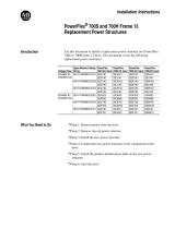
Figure P.1 400A and 600A SCR Bus Supply Schematic Diagram
The primary electrical components for the 400A and 600A SCR Bus Supply
are:
>°C
V1 V3
V4 V2V6
F6-F8
G4
K4
G1
K1
K3
G3
K6
G6
G2
K2
G5
K5
F1
F2
F3
V5
4
5
6
7
5
4
6
PE
L1
L2
L3
GND
K1
A2
A1
1
X1
3
X3
X2
L1 L2 L3
1
1
8
7
5
4
2
5
4
3
2
6
M
N
GND
L1
X1
12
115
0
1
4
2
5
6
8
7
9
10
11
F12
K1
22
4321 3313
443414
F5
F4
➋
➌
➊
➑
➏
➍
➎
Precharge
Board
+DC
-DC
Item Description
➊
Six-Pulse, Full-Wave, 3-Phase SCR Bridge Rectifier Unit connected to the line input and DC
Bus output terminals through semi-conductor protection fuses with trip indicator switches.
➋
Bus Supply Overtemperature Sensor located on the heat sink for thermal protection of the
SCR bridge rectifier.
➌
RC snubber circuit routed to the three input phases through semi-conductor protection
fuses with trip indicator switches.
➍
MOV snubber circuit routed to the three input phases.
➎
Precharge Board
➏
Enable Contactor (K1) for the precharge board.
➑
Cooling Blower connected to a customer-supplied 115V AC Power Supply. The customer’s
controls must, at a minimum, command the blower to run whenever contactor K1 is enabled.

P-6 Overview
PowerFlex SCR Bus Supply User Manual
Publication 20S-UM001G-EN-P
Figure P.2 1000A SCR Bus Supply Single Unit Schematic Diagram
The primary electrical components for the 1000A SCR Bus Supply Single
Unit are:
NOTE: There is no DC output fuse protection in the 1000A SCR unit.
>°C
F12
1
X1
3
X3
X2
G4
C4
G1
C1
C3
G3
C6
G6
G2
C2
G5
C5
K1
L1 L2L3
A2
A1
F6
F1
F4
F5
F2
F3
F7 - 11
L1 L4L5L3L2
K1
22
4321 3313
443414
X1
GND
12
115
0
1
4
2
5
6
8
7
9
10
11
3
2
V3
4
5
3
2
V5
4
5
3
2
V1
4
5
3
2
V4
45
3
2
V6
45
3
2
V2
45
L1
L2
L3
PE
1
5
4
3
2
1
8
7
5
4
2
6
M
N
GND
L1
➋
➌
➊
➑
➏
➍
➎
Precharge
Board
+ DC
- DC
Item Description
➊
Six-Pulse, Full-Wave, 3-Phase SCR Bridge Rectifier Unit connected to the line input and DC
Bus output terminals through semi-conductor protection fuses with trip indicator switches.
➋
Bus Supply Overtemperature Sensor located on the heat sink for thermal protection of the
SCR bridge rectifier.
➌
RC snubber circuit routed to the three input phases through semi-conductor protection
fuses with trip indicator switches.
➍
MOV snubber circuit routed to the three input phases.
➎
Precharge Board
➏
Enable Contactor (K1) for the precharge board.
➑
Cooling Blower connected to a customer-supplied 115V AC Power Supply. The customer’s
controls must, at a minimum, command the blower to run whenever contactor K1 is enabled.

Overview P-7
PowerFlex SCR Bus Supply User Manual
Publication 20S-UM001G-EN-P
Figure P.3 1000A SCR Bus Supply Master Unit Schematic Diagram
The primary electrical components for the 1000A SCR Bus Supply Master
Unit are:
NOTE: There is no DC output fuse protection in the 1000A SCR unit.
>°C
F12
K1
A2
A1
F6
F2
F1
F4
F5
F3
F7-11
L1 L4L5L3L2
K1
22
4321 3313
443414
X1
GND
12
115
0
1
4
2
5
6
8
7
9
10
11
3
2
V3
45
3
2
V5
45
3
2
V1
45
3
2
V4
45
3
2
V6
45
3
2
V2
45
L1
L2
L3
PE
+
-
+
+
-
X3
X4
X6
2
1
X1
3
X3
X2
L1 L2
L3
1
1
8
7
5
4
2
X5
5
4
3
2
6
1
3
4
5
6
7
9
12
11
10
8
12 7854126543X2
7
8
9
10
11
12
1
2
3
4
5
6
1
5
M
N
GND
L1
Precharge
Board
Gate Driver Board
➋
➌
➊
➑
➐
➏
➍
➎
+DC
-DC
To Gate
Driver X4
on the Slave
(Figure P.4)
Item Description
➊
Six-Pulse, Full-Wave, 3-Phase SCR Bridge Rectifier Unit connected to the line input and DC
Bus output terminals through semi-conductor protection fuses with trip indicator switches.
➋
Bus Supply Overtemperature Sensor located on the heat sink for thermal protection of the
SCR bridge rectifier.
➌
RC snubber circuit routed to the three input phases through semi-conductor protection
fuses with trip indicator switches.
➍
MOV snubber circuit routed to the three input phases.
➎
Precharge Board
➏
Enable Contactor (K1) for the precharge board.
➐
Gate Driver Board. The DC power supply is connected to a customer-supplied 115V AC Power
Supply.
➑
Cooling Blower connected to a customer-supplied 115V AC Power Supply. The customer’s
controls must, at a minimum, command the blower to run whenever contactor K1 is enabled.

P-8 Overview
PowerFlex SCR Bus Supply User Manual
Publication 20S-UM001G-EN-P
Figure P.4 1000A SCR Bus Supply Slave Unit Schematic Diagram
The primary electrical components for the 1000A SCR Bus Supply Slave
Unit are:
NOTE: There is no DC output fuse protection in the 1000A SCR Unit.
>°C
F12
F6
F2
F1
F4
F5
F3
F7-11
L1 L4L5L3L2
X1
GND
12
0
1
4
115
2
5
6
8
7
9
10
11
3
2
V3
45
3
2
V5
45
3
2
V1
45
3
2
V4
45
3
2
V6
45
3
2
V2
45
L1
L2
L3
PE
+
-
+
+
-
X3
X4
X6
2
X6
1
1
8
7
5
4
2
X5
5
4
3
2
6
1
3
4
5
6
7
9
12
11
10
8
1
2
7854126543X2
7
8
9
10
11
12
1
2
3
4
5
6
1
5
M
N
GND
L1
+DC
-DC
Gate Driver Board
From Gate
Driver X6
on the Master
(Figure P.3 or
previous Slave)
➋
➌
➊
➑
➐
➒
➍
To Gate
Driver X4
on the next
Slave
Item Description
➊
Six-Pulse, Full-Wave, 3-Phase SCR Bridge Rectifier Unit connected to the line input and DC
Bus output terminals through semi-conductor protection fuses with trip indicator switches.
➋
Bus Supply Overtemperature Sensor located on the heat sink for thermal protection of the
SCR bridge rectifier.
➌
RC snubber circuit routed to the three input phases through semi-conductor protection
fuses with trip indicator switches.
➍
MOV snubber circuit routed to the three input phases.
➐
Gate Driver Board. The DC power supply is connected to the customer-supplied 115V AC
Power Supply.
➑
Cooling Blower connected to a customer-supplied 115V AC Power Supply. The customer’s
controls must, at a minimum, command the blower to run whenever contactor K1 is enabled.
➒
Connection Cable (1 m) connects the gate firing pulses from the Master to the first Slave or
between any two Slaves (maximum 4).

PowerFlex SCR Bus Supply User Manual
Publication 20S-UM001G-EN-P
Chapter 1
Installation/Wiring
This chapter provides information on the installation and wiring of the
PowerFlex SCR Bus Supply.
Most start-up difficulties are the result of incorrect wiring. Every precaution
must be taken to assure that the wiring is done as instructed. All items must
be read and understood before the actual installation begins.
Topic Page
Opening the Cover
1-2
Minimum Mounting Clearances 1-3
AC Supply Source Considerations 1-4
General Grounding Requirements 1-5
Minimum Capacitance 1-6
Maximum Loading 1-6
Fusing 1-7
Power Wiring 1-7
Control Wiring 1-11
Jumper Settings 1-12
Disconnecting MOVs 1-14
Parallel Connection of Slave Units 1-15
1000A SCR Bus Supply Flexibility 1-16
1000A SCR Bus Supply Redundancy 1-17
SCR Bus Supply 12-Pulse Configuration 1-18
CE Conformity 1-19
!
ATTENTION: The following information is merely a guide for
proper installation. Rockwell Automation, Inc. cannot assume
responsibility for the compliance or the noncompliance to any
code, national, local or otherwise for the proper installation of this
product or associated equipment. A hazard of personal injury and/
or equipment damage exists if codes are ignored during
installation.

1-2 Installation/Wiring
PowerFlex SCR Bus Supply User Manual
Publication 20S-UM001G-EN-P
Opening the Cover
1. Remove the four fastening screws. (The steel sheet cover will stay in
place, even in the vertical position.)
2. Hold the cover with both hands at the bottom, and lift it upward about 2
cm (0.8 in.) and away from the enclosure (Figure 1.1
).
Figure 1.1 Opening the Cover

Installation/Wiring 1-3
PowerFlex SCR Bus Supply User Manual
Publication 20S-UM001G-EN-P
Minimum Mounting
Clearances
The cabinet air inlet and outlet areas for each SCR Bus Supply must be a
minimum of 200 cm
2
(31 in.
2
). The length-to-width ratio must not exceed
4:1.
Figure 1.2 Mounting Clearances
Ambient Operating Temperatures
The PowerFlex SCR Bus Supply is designed to operate at 0…40 °C
(32…104 °F) ambient without derating. For operation in ambients above
40 °C up to 50 °C (104 °F up to 122 °F), the PowerFlex SCR Bus Supply
output Amps must be derated by 1.2% per 1 °C for 400A unit, and by 1.0%
per 1 °C for 600A and 1000A units.
Ensure that proper cooling is provided to the SCR Bus Supply to maintain
the 40 °C rated specification. If the ambient temperature is exceeded, apply
the proper derate factors. Add exhaust fans to the front or top of the
enclosure bay and provide a filtered opening at the bottom of the cabinet
bay.
The SCR Bus Supply watt losses (from specification section) are 1200W at
400A, 1600W at 600A, 2700W at 480V 1000A, and 2800W at 690V
1000A. The three-phase AC line reactor watt losses are listed in the 1321
Power Conditioning Products Technical Data (publication 1321-TD001).
Because of the internal design of the SCR Bus Supply, it is NOT
recommended to rely on an air dam surrounding the SCR Bus Supply.
It is recommended that the system integrator completes a thermal evaluation
to ensure adequate cooling to maintain proper operating conditions for each
cabinet or bay. A minimum air exchange of 725 CFM per SCR Bus Supply
is recommended.
120 mm
(4.7 in.)
120 mm
(4.7 in.)
150 mm
(6 in.)
300 mm
(12 in.)
Air Flow Air FlowAir Flow
Air Outlet
PowerFlex
SCR
Bus Supply
PowerFlex
SCR
Bus Supply
Air Outlet
Air InletAir Inlet
Refer to Appendix A for detailed dimension information.
below fan

1-4 Installation/Wiring
PowerFlex SCR Bus Supply User Manual
Publication 20S-UM001G-EN-P
AC Supply Source
Considerations
The PowerFlex SCR Bus Supply is suitable for use on a circuit capable of
delivering a short circuit rating up to a maximum of 85,000 rms
symmetrical amperes.
If a Residual Current Detector (RCD) is used as a system ground fault
monitor, only Type B (adjustable) devices should be used to avoid nuisance
tripping.
Line Reactors
A minimum 3% rated three-phase AC line reactor must be installed for
minimum voltage drop unless the closest supply transformer is matched to
the kVA rating of the PowerFlex SCR Bus Supply. For recommended line
reactors, see Line Reactors
on page A-7.
Install one three-phase AC line reactor for each
SCR Bus Supply module. It
is recommended to maintain cable length symmetry between the
three-phase AC line reactors and the SCR Bus Supply connections. One
method is to mount the three-phase AC line reactors on the cabinet floor
under the SCR Bus Supply.
Important:It is recommended to keep all wired or bus bar connections
identical in size and length. This includes the AC line
connection to the three-phase AC line reactors and from the
three-phase AC line reactors to the SCR Bus Supply.
Unbalanced or Non-Solid Grounded Distribution Systems
Where the potential exists for abnormally high phase-to-ground voltages (in
excess of 125% of nominal), or the supply system is non-solid grounded,
refer to the Wiring and Grounding Guidelines for Pulse Width Modulated
(PWM) AC Drives (publication DRIVES-IN001).
!
ATTENTION: The PowerFlex SCR Bus Supply contains
protective MOVs that are referenced to ground. The MOVs should
be disconnected from ground if the SCR Bus Supply is installed on
any non-solid grounded power distribution system (IT-network).
For jumper location, see Figure 1.7 on page 1-11
.

Installation/Wiring 1-5
PowerFlex SCR Bus Supply User Manual
Publication 20S-UM001G-EN-P
General Grounding
Requirements
The Safety Ground terminal (PE) must be connected to the building
grounding scheme. Ground impedance must conform to the requirements
of national and local industrial safety regulations and/or electrical codes.
The integrity of all ground connections should be periodically checked.
For installations within a cabinet, a single safety ground point or ground bus
bar connected directly to building steel should be used. All circuits
including the AC input ground conductor should be grounded
independently and directly to this point/bar.
Figure 1.3 Typical Grounding
Safety Ground Terminal - PE
The Bus Supply safety ground (PE) must be connected to the customer
grounding scheme or earth ground. This is the safety ground for the Bus
Supply that is required by code. This point must be connected to adjacent
building steel (girder, joist), a floor ground rod, bus bar or building ground
grid. Grounding points must comply with national and local industrial
safety regulations and/or electrical codes.
RFI Filter Grounding
Using an external RFI filter may result in relatively high ground leakage
currents. Therefore, the filter must only be used in installations with
grounded AC supply systems and be permanently installed and solidly
grounded (bonded) to the building power distribution ground. Ensure that
the incoming supply neutral is solidly connected (bonded) to the same
building power distribution ground. Grounding must not rely on flexible
cables and should not include any form of plug or socket that would permit
inadvertent disconnection. Some local codes may require redundant ground
connections. The integrity of all connections should be periodically
checked. Refer to the instructions supplied with the filter.
+DC
SCR
Bus Supply
- DC
R (L1)
S (L2)
T (L3)
PE
Ground Grid, Girder or Ground
Rod (Building Ground Potential)

1-6 Installation/Wiring
PowerFlex SCR Bus Supply User Manual
Publication 20S-UM001G-EN-P
Minimum Capacitance
In order to commission and test the SCR Bus Supply, a minimum
capacitance is required. The design of the final installation must assure that
the minimum capacitance is connected whenever the bus supply is to be
enabled. If this minimum capacitance is not present, the bus supply internal
fault detection circuit will interpret the condition as a DC bus short and stop
pulse firing. The minimum capacitance (110 µF per SCR bus supply) may
be provided by an external capacitor bank (recommended) or a drive (as
long as the drive remains connected to the DC bus). NOTE: A capacitance
of 110 µF is typical of a 5 HP or 3.7 kW drive. To find DC bus capacitances
for specific PowerFlex drives, refer to Appendix A tables in the PowerFlex
AC Drives in Common Bus Configurations Application Guidelines
(publication DRIVES-AT002).
Maximum Loading
To avoid overloading the Bus Supply, the following requirement applies:
The DC Input current sum (Normal Duty rating at 40 °C/104 °F) of the
connected drive(s) must not exceed the Bus Supply continuous DC Bus
output current rating.
For the DC Input Current values of the drives, see tables in the respective
drive documentation.
Table 1.A
and Table 1.B provide guidance on the nominal operation of the
SCR Bus Supply. No overload capability is built into the tables.
Important:See “Output Ratings
” in Appendix A for overload capability.
When an overload is being utilized in connected drives or products, that
overload current must be accounted for in the calculation to properly size
the SCR Bus Supply.
Table 1.A Normal Duty ND (110%, 1 minute; 150%, 3 seconds)
Table 1.B Heavy Duty HD (150%, 1 minute; 200%, 3 seconds)
Drive Rating Drive Output Current Drive DC Input Current SCR Bus Supply
(1)
DC
Voltage
ND
Power
ND Output
Currents
ND Output
Current Sum
ND DC Input
Currents
ND DC Input
Current Sum
Maximum DC
Output Amps
AC Input
Voltage
540V 3 x 110 kW
1 x 45 kW
3 x 205 = 615A
1 x 85 = 85A
700A 3 x 226 = 678A
1 x 95 = 95A
773A 1000A 400V
650V 3 x 60 HP
1 x 30 HP
3 x 77 = 231A
1 x 40 = 40A
271A 3 x 84.5 = 253.5A
1 x 42.9 = 42.9A
297A 400A 480V
(1)
No overload capability.
Drive Rating Drive Output Current Drive DC Input Current SCR Bus Supply
(1)
DC
Voltage
HD
Power
HD Output
Currents
HD Output
Current Sum
HD DC Input
Currents
HD DC Input
Current Sum
Maximum DC
Output Amps
AC Input
Voltage
540V 3 x 90 kW 3 x 170 = 510A 510A 3 x 192.3 = 577A 577A 600A 400V
(1)
No overload capability.
/