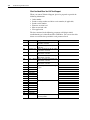
Rockwell PowerFlex 700H User manual
- Category
- Power adapters & inverters
- Type
- User manual
This manual is also suitable for

FRAME 10 HARDWARE SERVICE MANUAL
200-250 kW, 400V
300-450 HP, 480V
250-450 HP, 600V
250-400 kW, 690V
PowerFlex® 700S / 700H
Adjustable Frequency AC Drives

Important User Information
Solid state equipment has operational characteristics differing from those of
electromechanical equipment. Safety Guidelines for the Application,
Installation and Maintenance of Solid State Controls (Publication SGI-1.1
available from your local Rockwell Automation sales office or online at
http://
www.rockwellautomation.com/literature) describes some important differences
between solid state equipment and hard-wired electromechanical devices.
Because of this difference, and also because of the wide variety of uses for solid
state equipment, all persons responsible for applying this equipment must
satisfy themselves that each intended application of this equipment is
acceptable.
In no event will Rockwell Automation, Inc. be responsible or liable for indirect
or consequential damages resulting from the use or application of this
equipment.
The examples and diagrams in this manual are included solely for illustrative
purposes. Because of the many variables and requirements associated with any
particular installation, Rockwell Automation, Inc. cannot assume responsibility
or liability for actual use based on the examples and diagrams.
No patent liability is assumed by Rockwell Automation, Inc. with respect to use
of information, circuits, equipment, or software described in this manual.
Reproduction of the contents of this manual, in whole or in part, without
written permission of Rockwell Automation, Inc. is prohibited.
Throughout this manual, when necessary we use notes to make you aware of
safety considerations.
Important: Identifies information that is critical for successful application and
understanding of the product.
PowerFlex, DriveExplorer, DriveExecutive, DPI, and SCANport are either trademarks or registered trademarks of Rockwell Automation, Inc.
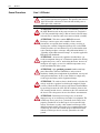
!
WARNING: Identifies information about practices or
circumstances that can cause an explosion in a hazardous
environment, which may lead to personal injury or death, property
damage, or economic loss.
!
ATTENTION: Identifies information about practices or
circumstances that can lead to personal injury or death, property
damage, or economic loss. Attentions help you identify a hazard,
avoid a hazard, and recognize the consequences.
Shock Hazard labels may be located on or inside the equipment
(e.g., drive or motor) to alert people that dangerous voltage may be
present.
Burn Hazard labels may be located on or inside the equipment
(e.g., drive or motor) to alert people that surfaces may be at
dangerous temperatures.

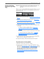
Summary of Changes
Manual Updates
Current Revision
This information summarizes the changes made to the PowerFlex
®
700S
and 700H Drives Frame 10 - Hardware Service Manual, publication
PFLEX-TG002..., since the April 2007 release.
Previous Revision
This information summarizes the changes made to the PowerFlex
®
700S
and 700H Drives Frame 10 - Hardware Service Manual, publication
PFLEX-TG002..., since the July 2005 release.
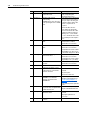
Change See Page...
Updated the 700S and 700H faults. 1-2
Removed the “Diagnostic Procedures by Symptom” diagrams and replaced them with
the new “Common Drive Conditions and Corrective Actions” tables.
1-17
Added the “Technical Support Options” section. 1-19
Removed the “Active” Gate Driver Board measurements procedures from Chapter 2.
Updated the “Checking the Rectifying Module” procedures to include the new Series B
Rectifying board.
2-9
Added procedure for removing the precharging resistors on series B rectifiers. 3-32
Updated the “Start-Up After Repair” procedures. 4-1
Updated the “Right-Hand Side” and “Left-Hand Side Power Structure” spare parts lists. C-4
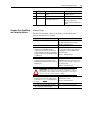
Change See Page...
Updated the 700S hardware faults 1-2
Removed references to brake option in the “Conducting Forward and Reverse Biased
Diode Tests for Major Power Components” (brake option not available on PowerFlex
700H/S Frame 10 drives)
2-3
Added Removal of PowerFlex 700S Phase II Control 3-6
Added the Removal of the Common Mode Filter Board 3-9
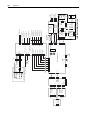
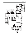
Updated the Circuit Board Connections Schematics to include the X50 Terminal Block
and Common Mode Filter circuit board
B-1
Updated the Spare Parts Lists for the Disassembly / Assembly Drawings C-1
Added an Index Index-1

soc-ii Summary of Changes
Notes:

Table of Contents
Important User Information . . . . . . . . . . . . . . . . . . . . . . . . . . . . . . . . . . . . . . . . . . . . . . . 1-2
Summary of
Changes
Manual Updates
Current Revision . . . . . . . . . . . . . . . . . . . . . . . . . . . . . . . . . . . . . . . . . . . . . . . . . . . . . . . . . S-i
Previous Revision . . . . . . . . . . . . . . . . . . . . . . . . . . . . . . . . . . . . . . . . . . . . . . . . . . . . . . . . S-i
Preface Overview
Who Should Use this Manual? . . . . . . . . . . . . . . . . . . . . . . . . . . . . . . . . . . . . . . . . . . . . . P-1
What is in this Manual . . . . . . . . . . . . . . . . . . . . . . . . . . . . . . . . . . . . . . . . . . . . . . . . . . . P-1
What is Not in this Manual . . . . . . . . . . . . . . . . . . . . . . . . . . . . . . . . . . . . . . . . . . . . . . . . P-2
Reference Materials . . . . . . . . . . . . . . . . . . . . . . . . . . . . . . . . . . . . . . . . . . . . . . . . . . . . . P-2
Understanding Manual Conventions. . . . . . . . . . . . . . . . . . . . . . . . . . . . . . . . . . . . . . . . . P-3
Additional Support Available on Internet . . . . . . . . . . . . . . . . . . . . . . . . . . . . . . . . . . . . . P-3
General Precautions . . . . . . . . . . . . . . . . . . . . . . . . . . . . . . . . . . . . . . . . . . . . . . . . . . . . . P-4
Chapter 1 Troubleshooting and Error Codes
Creating Fault Reports . . . . . . . . . . . . . . . . . . . . . . . . . . . . . . . . . . . . . . . . . . . . . . . . . . . 1-2
Addressing 700S Faults. . . . . . . . . . . . . . . . . . . . . . . . . . . . . . . . . . . . . . . . . . . . . . . . . . . 1-2
Addressing 700H Faults . . . . . . . . . . . . . . . . . . . . . . . . . . . . . . . . . . . . . . . . . . . . . . . . . 1-13
Common Drive Conditions and Corrective Actions . . . . . . . . . . . . . . . . . . . . . . . . . . . . 1-17
Technical Support Options . . . . . . . . . . . . . . . . . . . . . . . . . . . . . . . . . . . . . . . . . . . . . . . 1-19
Chapter 2 Component Test Procedures
Viewing the 700H Diagnostic LED . . . . . . . . . . . . . . . . . . . . . . . . . . . . . . . . . . . . . . . . . 2-1
Performing Visual Inspections . . . . . . . . . . . . . . . . . . . . . . . . . . . . . . . . . . . . . . . . . . . . . 2-2
Conducting Forward and Reverse Biased Diode Tests for Major Power Components. . . 2-3
Conducting Gate Driver Board Gate Interface Resistance Measurements . . . . . . . . . . . . 2-7
Checking the Rectifying Module (on AC Input Drives Only) . . . . . . . . . . . . . . . . . . . . . 2-9
Checking the Fan Inverters and Main Fans. . . . . . . . . . . . . . . . . . . . . . . . . . . . . . . . . . . 2-12

2
Chapter 3 Access Procedures
Torque Specifications. . . . . . . . . . . . . . . . . . . . . . . . . . . . . . . . . . . . . . . . . . . . . . . . . . . . . 3-2
Removing Power from Drive. . . . . . . . . . . . . . . . . . . . . . . . . . . . . . . . . . . . . . . . . . . . . . . 3-3
Removing the DPI / HIM Assembly . . . . . . . . . . . . . . . . . . . . . . . . . . . . . . . . . . . . . . . . . 3-4
Installing the DPI / HIM Assembly. . . . . . . . . . . . . . . . . . . . . . . . . . . . . . . . . . . . . . . . . . 3-5
Removing the 700S Phase I Control Assembly. . . . . . . . . . . . . . . . . . . . . . . . . . . . . . . . . 3-5
Installing the 700S Phase I Control Assembly . . . . . . . . . . . . . . . . . . . . . . . . . . . . . . . . . 3-6
Removing the 700S Phase II Control Assembly . . . . . . . . . . . . . . . . . . . . . . . . . . . . . . . . 3-6
Installing the 700S Phase II Control Assembly. . . . . . . . . . . . . . . . . . . . . . . . . . . . . . . . . 3-8
Removing the Common Mode Filter Circuit Board . . . . . . . . . . . . . . . . . . . . . . . . . . . . . 3-9
Installing the Common Mode Filter Circuit Board . . . . . . . . . . . . . . . . . . . . . . . . . . . . . 3-10
Removing the 700S High Power Fiber Optic Interface Circuit Board . . . . . . . . . . . . . . 3-11
Installing the 700S High Power Fiber Optic Interface Circuit Board . . . . . . . . . . . . . . . 3-12
Removing the 700H I/O Circuit Boards and Control Assembly . . . . . . . . . . . . . . . . . . . 3-12
Installing the 700H I/O Circuit Boards and Control Assembly. . . . . . . . . . . . . . . . . . . . 3-13
Removing the 700H Fiber Optic Adapter Circuit Board. . . . . . . . . . . . . . . . . . . . . . . . . 3-14
Installing the 700H Fiber Optic Adapter Circuit Board . . . . . . . . . . . . . . . . . . . . . . . . . 3-15
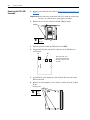
Removing the Covers from the Power Structure . . . . . . . . . . . . . . . . . . . . . . . . . . . . . . . 3-15
Installing the Protective Covers . . . . . . . . . . . . . . . . . . . . . . . . . . . . . . . . . . . . . . . . . . . . 3-19
Removing the 700S Voltage Feedback Circuit Board . . . . . . . . . . . . . . . . . . . . . . . . . . . 3-20
Installing the 700S Voltage Feedback Circuit Board. . . . . . . . . . . . . . . . . . . . . . . . . . . . 3-21
Removing the Gate Driver and Adapter Circuit Boards . . . . . . . . . . . . . . . . . . . . . . . . . 3-22
Installing the Gate Driver and Adapter Circuit Boards . . . . . . . . . . . . . . . . . . . . . . . . . . 3-26
Removing the Power Structure from the Drive Enclosure . . . . . . . . . . . . . . . . . . . . . . . 3-27
Installing the Power Structure in the Drive Enclosure. . . . . . . . . . . . . . . . . . . . . . . . . . . 3-27
Removing the Main Fans. . . . . . . . . . . . . . . . . . . . . . . . . . . . . . . . . . . . . . . . . . . . . . . . . 3-28
Installing the Main Fans . . . . . . . . . . . . . . . . . . . . . . . . . . . . . . . . . . . . . . . . . . . . . . . . . 3-28
Removing the ASIC Circuit Board . . . . . . . . . . . . . . . . . . . . . . . . . . . . . . . . . . . . . . . . . 3-29
Installing the ASIC Circuit Board . . . . . . . . . . . . . . . . . . . . . . . . . . . . . . . . . . . . . . . . . . 3-30
Removing the Rectifying Circuit Board . . . . . . . . . . . . . . . . . . . . . . . . . . . . . . . . . . . . . 3-31
Installing the Rectifying Circuit Board . . . . . . . . . . . . . . . . . . . . . . . . . . . . . . . . . . . . . . 3-31
Removing the Precharging Resistors from Series B Drives . . . . . . . . . . . . . . . . . . . . . . 3-32
Installing the Precharging Resistors on Series B Drives . . . . . . . . . . . . . . . . . . . . . . . . . 3-33
Removing the Left-Side Output Power Module . . . . . . . . . . . . . . . . . . . . . . . . . . . . . . . 3-34
Installing the Left-Side Output Power Module . . . . . . . . . . . . . . . . . . . . . . . . . . . . . . . . 3-36
Removing the Right-Side Output Power Module and Rectifying Module . . . . . . . . . . . 3-36
Installing the Right-Side Output Power Module and Rectifying Module . . . . . . . . . . . . 3-40
Removing the Fan Inverters. . . . . . . . . . . . . . . . . . . . . . . . . . . . . . . . . . . . . . . . . . . . . . . 3-40
Installing the Fan Inverters . . . . . . . . . . . . . . . . . . . . . . . . . . . . . . . . . . . . . . . . . . . . . . . 3-43
Removing the DC Bus Capacitors. . . . . . . . . . . . . . . . . . . . . . . . . . . . . . . . . . . . . . . . . . 3-44
Installing the DC Bus Capacitors . . . . . . . . . . . . . . . . . . . . . . . . . . . . . . . . . . . . . . . . . . 3-45
Chapter 4 Start-Up After Repair
Loading the 700H EEPROM . . . . . . . . . . . . . . . . . . . . . . . . . . . . . . . . . . . . . . . . . . . . . . . 4-1
Before Applying Power to the Drive . . . . . . . . . . . . . . . . . . . . . . . . . . . . . . . . . . . . . . . . . 4-2
Testing Without the Motor. . . . . . . . . . . . . . . . . . . . . . . . . . . . . . . . . . . . . . . . . . . . . . . . . 4-2
Performing the Power Circuit Diagnostic Test on a 700S Drive. . . . . . . . . . . . . . . . . . . . 4-3
Testing With the Motor Without a Mechanical Load . . . . . . . . . . . . . . . . . . . . . . . . . . . . 4-4

3
Appendix A Service Tools and Equipment
Software Tools. . . . . . . . . . . . . . . . . . . . . . . . . . . . . . . . . . . . . . . . . . . . . . . . . . . . . . . . . . A-1
Service Tools. . . . . . . . . . . . . . . . . . . . . . . . . . . . . . . . . . . . . . . . . . . . . . . . . . . . . . . . . . . A-1
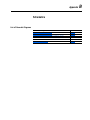
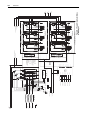
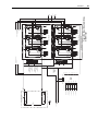
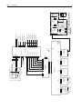
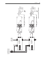
Appendix B Schematics
List of Schematic Diagrams . . . . . . . . . . . . . . . . . . . . . . . . . . . . . . . . . . . . . . . . . . . . . . . B-1
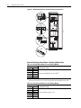
Appendix C Disassembly / Assembly Diagrams
Disassembly/Assembly Diagrams and Spare Parts Numbers . . . . . . . . . . . . . . . . . . . . . . C-1
Index

4

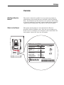
Preface
Overview
Who Should Use this
Manual?
This manual is intended for qualified service personnel responsible for
troubleshooting and repairing high power PowerFlex 700S and 700H AC
Drives. You should have previous experience with, and basic understanding
of, electrical terminology, procedures, required troubleshooting equipment,
equipment protection procedures and methods, and safety precautions.
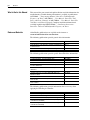
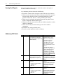
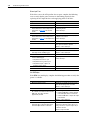
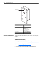
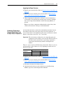
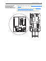
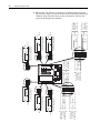
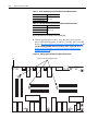
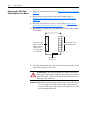
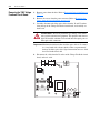
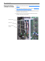
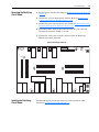
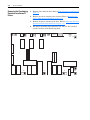
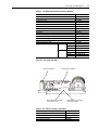
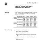
What is in this Manual
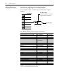
This manual contains hardware service information for Frame 10
PowerFlex 700S and 700H drives only. Verify that you are working on a
Frame 10 drive by checking the data nameplate on the Control Frame. The
frame number is printed just above the serial number.
Cat No.
20D
J
300 N 0 NNNBNNNN
UL Open Type/IP00
540V 650V
Normal Duty Power
160 kW
132 kW
250 kW
200 kW
Heavy Duty Power
DC Voltage Range
462 - 594
350
583 - 713
350
Amps
Input: DC,
AC Voltage Range
0 - 400
50 Hz
0 - 460
60 Hz
Base Hz (default)
Output: 3 Phase, 0 - 320Hz
Continuous Amps
300/245
330/368
300/245
330/368
1 Min Overload Amps
2 Sec Overload Amps
450/490 450/490
MFD. in 1989 on Nov 9
Serial Number: 2622381652
2622381652
MADE IN THE USA (FAC 1B)
Series: A
Standard I/O: NONE
Original Firmware No. 2.04
U
L
USC
Æ
LISTED
IND CONT EQ
Cat No.
20D
J
500 N 0 NNNBNNNN
UL Open Type/IP00
540V 650V
Normal Duty Power
250 kW
200 kW
450 kW
500 kW
Heavy Duty Power
DC Voltage Range
462 - 594
350
583 - 713
350
Amps
Input: DC,
AC Voltage Range
0 - 400
50 Hz
0 - 460
60 Hz
Base Hz (default)
Output: 3 Phase, 0 - 320Hz
Continuous Amps
420/500
630/550
420/500
630/550
1 Min Overload Amps
2 Sec Overload Amps
840/630 840/630
MFD. in 1989 on Nov 9 Frame #: 10
Serial Number: 2622381652
2622381652
MADE IN THE USA (FAC 1B)
Series: A
Standard I/O: NONE
Original Firmware No. 2.04
U
L
USC
Æ
LISTED
IND CONT EQ
9D42
Frame #: 10
ahw0981.eps

p-2 Overview
What is Not in this Manual
This manual does not contain in depth installation and fault information for
troubleshooting. Troubleshooting information is available in publications
20C-PM001…, Programming Manual - PowerFlex 700H Adjustable
Frequency AC Drive, 20D-UM001…, User Manual - PowerFlex 700S
Drive with Phase I Control, or 20D-UM006…, User Manual - PowerFlex
700S Drive with Phase II Control. Complete installation information is
available in publication PFLEX-IN006…, Installation Instructions -
PowerFlex 700S and 700H Adjustable Frequency AC Drive.
Reference Materials
Allen-Bradley publications are available on the internet at
www.rockwellautomation.com/literature.
The following publications provide general drive information.
The following publications provide specific PowerFlex drive information.
The following publications provide information that is necessary when
applying the DriveLogix Controller.
Title Publication
Wiring and Grounding Guide, (PWM) AC Drives DRIVES-IN001...
Safety Guidelines for the Application, Installation and Maintenance of
Solid State Control
SGI-1.1
A Global Reference Guide for Reading Schematic Diagrams 100-2.10
Guarding Against Electrostatic Damage 8000-4.5.2
Title Publication
Programming Manual - PowerFlex 700H AC Drive 20C-PM001...
User Manual - PowerFlex 700S Drive with Phase I Control 20D-UM001...
User Manual - PowerFlex 700S Drive with Phase II Control 20D-UM006...
Installation Instructions - Hi-Resolution Feedback Option Card for
PowerFlex 700S Drives
20D-IN001...
Installation Instructions - Multi Device Interface Option for PowerFlex
700S Drives
20D-IN004...
Installation Instructions - Main Control Board PowerFlex 700S Drives 20D-IN005...
Installation Instructions - PowerFlex 700S /700H High Power
Maintenance Stand
20D-IN014...
Installation Instructions - PowerFlex 700S and 700H Drives PFLEX-IN006...
Reference Manual - PowerFlex Adjustable Frequency Drive with
Phase I Control
PFLEX-RM002...
Reference Manual - PowerFlex Adjustable Frequency Drive with
Phase II Control
PFLEX-RM003...
Title Publication
User Manual - DriveLogix System 20D-UM002...
Installation Instructions - DriveLogix Controller 20D-IN002...
Installation Instructions - Memory Expansion for DriveLogix Controller 20D-IN007...
ControlNet Daughtercard Installation Instructions (Catalog Numbers
1788-CNC and 1788-CNCR)
1788-IN002...
ControlNet Daughtercard Installation Instructions (Catalog Numbers
1788-CNF and 1788-CNFR)
1788-IN005...

Overview p-3
Understanding Manual
Conventions
Terms
The following words are used throughout the manual to describe an action:
Cross References
“Figure 2.2 on page 2-6” is a cross reference to figure 2.2 on page 5 of
Chapter 2.
“Figure C.1 on page C-2
” is a cross reference to figure C.1 on page 2 of
Appendix C.
Additional Support
Available on Internet
Additional troubleshooting information and software tools are available on
the Allen-Bradley Drives Support Website (http://www.ab.com/support/
abdrives/).
Word Meaning
Can Possible, able to do something
Cannot Not possible, not able to do something
May Permitted, allowed
Must Unavoidable, you must do this
Shall Required and necessary
Should Recommended
Should Not Not recommended

p-4 Overview
General Precautions
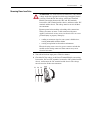
Class 1 LED Product
!
ATTENTION: Hazard of permanent eye damage exists when
using optical transmission equipment. This product emits intense
light and invisible radiation. Do not look into module ports or
fiber-optic cable connectors.
!
ATTENTION: The sheet metal cover and mounting screws on
the ASIC Board located on the power structure are energized at
(-) DC bus potential high voltage. Risk of electrical shock, injury,
or death exists if someone comes into contact with the assembly.
!
ATTENTION: This drive contains ESD (Electrostatic
Discharge) sensitive parts and assemblies. Static control
precautions are required when installing, testing, servicing or
repairing this assembly. Component damage may result if ESD
control procedures are not followed. If you are not familiar with
static control procedures, reference A-B publication 8000-4.5.2,
“Guarding Against Electrostatic Damage” or any other applicable
ESD protection handbook.
!
ATTENTION: An incorrectly applied or installed drive can
result in component damage or a reduction in product life. Wiring
or application errors, such as, undersizing the motor, incorrect or
inadequate AC supply, or excessive ambient temperatures may
result in malfunction of the system.
!
ATTENTION: Only qualified personnel familiar with high
power PowerFlex 700S and 700H Drives and associated
machinery should plan or implement the installation, start-up and
subsequent maintenance of the system. Failure to comply may
result in personal injury and/or equipment damage.
!
ATTENTION: To avoid an electric shock hazard, verify that the
voltage on the bus capacitors has discharged completely before
servicing. Check the DC bus voltage at the Power Terminal Block
by measuring between the +DC and -DC terminals, between the
+DC terminal and the chassis, and between the -DC terminal and
the chassis. The voltage must be zero for all three measurements.
!
ATTENTION: Potentially fatal voltages may result from
improper usage of an oscilloscope and other test equipment. The
oscilloscope chassis may be at a potentially fatal voltage if not
properly grounded. If an oscilloscope is used to measure high
voltage waveforms, use only a dual channel oscilloscope in the
differential mode with X 100 probes. It is recommended that the
oscilloscope be used in the A minus B Quasi-differential mode
with the oscilloscope chassis correctly grounded to an earth
ground.

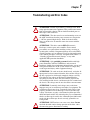
Chapter 1
Troubleshooting and Error Codes
!
ATTENTION: Hazard of permanent eye damage exists when
using optical transmission equipment. This product emits intense
light and invisible radiation. Do not look into module ports or
fiber-optic cable connectors.
!
ATTENTION: The sheet metal cover and mounting screws on
the ASIC board located on the power structure are energized at
(-) DC bus potential high voltage. Risk of electrical shock,
injury, or death exists if someone comes into contact with the
assembly.
!
ATTENTION: This drive contains ESD (Electrostatic
Discharge) sensitive parts and assemblies. Static control
precautions are required when installing, testing, servicing or
repairing this assembly. Component damage may result if ESD
control procedures are not followed. If you are not familiar with
static control procedures, reference A-B publication 8000-4.5.2,
“Guarding Against Electrostatic Damage” or any other
applicable ESD protection handbook.
!
ATTENTION: Only qualified personnel familiar with high
power PowerFlex 700S and 700H Drives and associated
machinery should plan or implement the installation, start-up and
subsequent maintenance of the system. Failure to comply may
result in personal injury and/or equipment damage.
!
ATTENTION: To avoid an electric shock hazard, verify that all
input power has been removed from the drive and the voltage on
the bus capacitors has discharged completely before servicing.
Check the DC bus voltage at the Power Terminal Block by
measuring between the +DC and -DC terminals, between the
+DC terminal and the chassis, and between the -DC terminal and
the chassis. The voltage must be zero for all three measurements.
!
ATTENTION: Potentially fatal voltages may result from
improper usage of an oscilloscope and other test equipment. The
oscilloscope chassis may be at a potentially fatal voltage if not
properly grounded. If an oscilloscope is used to measure high
voltage waveforms, use only a dual channel oscilloscope in the
differential mode with X 100, isolated probes. It is recommended
that the oscilloscope be used in the A minus B Quasi-differential
mode with the oscilloscope chassis correctly grounded to an
earth ground.
!
ATTENTION: HOT surfaces can cause severe burns. Do not
touch the heatsink surface during operation of the drive. After
disconnecting power allow time for cooling.

1-2 Troubleshooting and Error Codes
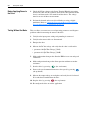
Creating Fault Reports
Clear and complete fault reports are critical for analysis and repair of
modules returned to the factory.
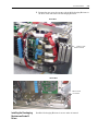
At a minimum, perform and record the following:
• Record the contents of the fault queue (faults and times of occurrence)
• Make record of any burn marks on the rectifying module, DC-capacitors,
inverter bridge, charging resistors, balancing/precharging resistors,
printed circuit boards, bus bars, cabling and fiber-optic cabling
• Make record of any liquid and condensation marks on printed circuit
boards, components and mechanical parts
• Make record of the amount of dust and other additional particles on drive
and drive components
• Make record of any mechanical damage to the drive and drive
components
• Record the size and type of main fuses
• Record any other important marks and damage
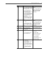
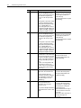
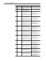
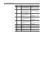
Addressing 700S Faults
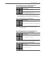
No. Name Description Action (if appropriate)
1 Abs Ovespd Det Motor speed has exceeded the limits
set in parameters 75 [Rev Speed
Limit], 76 [Fwd Speed Limit] and 335
[Abs OverSpd Lim]
• Check to see if the encoder
feedback polarity is correct.
• Check to see if the drive is in
torque mode, selected in
parameter 110 [Speed/
TorqueMode] value 2 “Torque
Ref”. If the drive is in torque
mode, verify that there is a load
present.
• Verify min./max. settings in
parameters 75 [Rev Speed Lim]
and Par 76 [Fwd Speed Lim].
Check to see if the load is
overhauling. If it is overhauling,
turn the bus regulator off using
parameter 414 [Brake/Bus Cnfg]
bit 2 “BusRef High”.
2 Vref Decel Fail The value of parameter 301 [Motor
Spd Ref] has failed to decrease
during a ramp to zero speed stop.
• This may be due to a speed trim
from parameters 21 [Speed Trim
1], 22 [Speed Trim 2] or 23 [Speed
Trim 3].
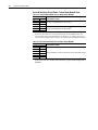
3 Encoder 0 Loss One of the following has occurred on
encoder 0:
• missing encoder (broken wire)
• quadrature error
• phase loss
• Reconnect encoder or replace
encoder.
• Configured with parameters 365
[Fdbk LsCnfg Pri], 366 [Fdbk
LsCnfg Alt], and 367 [Fdbk
LsCnfgPosit]
4 Encoder 1 Loss One of the following has occurred on
encoder 1:
• missing encoder (broken wire)
• quadrature error
• phase loss
• Reconnect encoder or replace
encoder.
• Configured with parameters 365
[Fdbk LsCnfg Pri], 366 [Fdbk
LsCnfg Alt], and 367 [Fdbk
LsCnfgPosit]

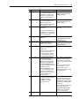
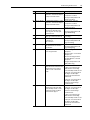
Troubleshooting and Error Codes 1-3
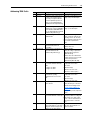
5 Opt Port 0 Loss A fault on port 0 of the Hi-Resolution
Encoder Feedback Option Card, MDI
Option Card, Heidenhain, or Resolver
Feedback Option Card has occurred.
• Parameter 260 [Stegmann0
Status] displays the fault status for
port 0 of the Hi-Resolution
Encoder Feedback Option Card.
• Parameter 264 [Heidenhain0 Stat]
displays the fault status for port 0
of the Heidenhain Feedback
Option Card.
• Parameter 269 [Resolver0 Status]
displays the fault status for port 0
of the Resolver Feedback Option
Card.
• Reconnect encoder or replace
encoder
• Reconnect option feedback card
• Configured with parameters 365
[Fdbk LsCnfg Pri], 366 [Fdbk
LsCnfg Alt], and 367 [Fdbk
LsCnfgPosit]
6 Opt Port 1 Loss The Linear sensor portion of the MDI
feedback option card has detected a
fault condition.
• Parameter 286 [Linear1 Status]
displays the fault status for linear
portion of the MDI feedback Option
Card.
• Reconnect encoder or replace
encoder
• Reconnect option feedback card
• Configured with parameters 365
[Fdbk LsCnfg Pri], 366 [Fdbk
LsCnfg Alt], and 367 [Fdbk
LsCnfgPosit]
7 Params Defaulted All parameters are reset to default by
user.
(Informational only.)
8 SLink HW Fail A fault on loading SynchLink
firmware into FPGA on Main Control
Board at power up.
• Replace Main Control Board
9 SLink Comm Fail A SynchLink communication fault has
occurred.
• Parameter 902 [SL Error Status]
displays SynchLink errors.
• Verify the SynchLink configuration
in parameters:
• 904 [SL Node Cnfg]
• 905 [SL Rx CommFormat], and
• 910 [SL Tx CommFormat]
•
Reconnect SynchLink
communication fibers
• Configured with parameter 384
[SL CommLoss Cnfg]
10 Drive Power Loss • DC Bus voltage has fallen below
the minimum value
• Parameter 306 [DC Bus Voltage]
displays bus voltage
• Parameter 330 [Fault TP Data]
displays the minimum value when
parameter 329 [Fault TP Sel] is set
to five
• The drive must first complete
precharge before this check is
made
• Verify AC line power
No. Name Description Action (if appropriate)

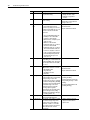
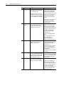
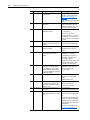
1-4 Troubleshooting and Error Codes
11 Motor OLoad Trip A motor overload trip has occurred.
Parameter 308 [Output Current] is
squared, scaled and integrated over
time. When this integrated value
exceeds 1.0, this Exception Event
occurs.
The integrator's output can be viewed
in parameter 330 [Fault TP Data]
when parameter 329 [Fault TP Sel] is
set to 13 “Mtr OL Outpt”. The
overload integration rate is affected
by parameters 336 [Motor OL Factor],
337 [Mtr I2T Curr Min], 338 [Mtr I2T
Spd Min] and 339 [Mtr I2T Calibrat].
• Reduce the mechanical load
• Enter the correct motor nameplate
full load amps in parameter 2
[Motor NP FLA]
• Configure with parameter 371 [Mtr
OL Trip Cnfg]
12 Motor OLoad Pend A motor overload is pending.
Parameter 308 [Output Current] is
squared, scaled and integrated over
time. When this integrated value
exceeds 0.5, this exception event
occurs.
The integrator's output can be viewed
in parameter 330 [Fault TP Data]
when parameter 329 [Fault TP Sel] is
set to 13 “Mtr OL Outpt”. The
overload integration rate is affected
by parameters 336 [Motor OL Factor],
337 [Mtr I2T Curr Min], 338 [Mtr I2T
Spd Min] and 339 [Mtr I2T Calibrat].
• Reduce the mechanical load
• Enter the correct motor nameplate
full load amps in parameter 2
[Motor NP FLA]
• Configure with parameter 372 [Mtr
OL Pend Cnfg]
13 Motor Stalled The motor has stalled. These three
conditions have occurred at the same
time for the amount of time specified
in parameter 373 [Motor Stall Time]:
1.) Drive is not stopped (parameter
150 [Logic State Mach] not equal to
zero)
2.) Drive is on limit (parameter 304
[Limit Status] not equal to zero)
3.) Drive is at zero speed (parameter
155 [Logic Status] / bit 13 “At Zero
Spd” is set).
• Increase torque limit
• Reduce mechanical load
• Configured with parameter 374
[Motor Stall Cnfg]
14 Inv OTemp Pend Parameter 313 [Heatsink Temp] is
within 10°C of the maximum value.
View the maximum heat sink
temperature in parameter 348 [Drive
OL TP Data] when parameter 347
[Drive OL TP Sel] is set to 30 -
“fMaxHsDegc”.
• Reduce the mechanical load
• Lower the ambient temperature
• Configured with parameter 375
[Inv OT Pend Cnfg]
15 Inv OTemp Trip Parameter 313 [Heatsink Temp] is
above the maximum limit or
temperature sensor has failed
(shorted or open).
See parameter 346 [Drive OL Status]
/ bit 0 “NTC Shorted” and bit 1 “NTC
Open”.
• Reduce the mechanical load
• Lower the ambient temperature
• Verify that the cooling fan(s) and
fan inverter(s) are running and
functioning properly.
• Check the heatsink for blockage or
excessive dirt and clear/clean as
necessary.
• Check the air filters (if present) for
blockage and replace as
necessary.
No. Name Description Action (if appropriate)

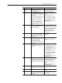
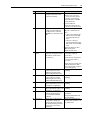
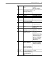
Troubleshooting and Error Codes 1-5
16 Inv OLoad Pend The drive's operating point is
approaching the intermittent current
rating limitation. If output current
remains at or above present levels,
an inverter overload condition will
occur.
• Reduce the load on the drive
• Configured with parameter 376
[Inv OL Pend Cnfg]
17 Inv OLoad Trip The drive's operating point has
exceeded the intermittent current
rating and a foldback to the
continuous rating in parameter 400
[Rated Amps] has occurred.
• Reduce the mechanical load
• Configured with parameter 377
[Inv OL Trip Cnfg]
18 Ext Fault Input A digital input has detected an
external fault.
Enter a value of 3 “Ext Fault” or 38
“ExtFault Inv” in one of the [Digin x
Sel] parameters to configure an input
to detect an external fault.
Configured with parameter 379 [Ext
Flt/Alm Cnfg]
19 DSP Memory Error Flash memory does not match the
SRAM memory
• Cycle the drive power
• If the fault remains, replace the
Main Control Board
20 DSP Device Error A DSP (Velocity Position Loop)
interrupt task has not been
completed in the allotted time.
• Cycle the drive power
• If the fault remains, replace the
Main Control Board
22 Over Frequency Encoderless algorithm fails to
converge on correct speed. Two
possible causes:
1.) Velocity regulator is attempting to
run below motor’s slip speed.
2.) Frequency regulator “pulls out”
and commanded motor frequency
slows to maximum frequency limit.
23 MC Commissn Fail The drive has failed to complete
either the Motor Autotuning
procedure or the Power Circuits
Diagnostics test. Parameters 463
[MC Diag Error 1], 464 [MC Diag
Error 2] and 465 [MC Diag Error 3]
display Motor Autotuning and Power
Circuit Diagnostic faults.
Parameter 465 [MC Diag Error 3] -
Drive current, inductance, voltage
and speed are not within motor
nameplate specifications. This fault
occur most frequently on low
horsepower motors.
• Verify that motor nameplate data is
entered correctly into the drive.
• Verify the motor is wired for the
correction voltage entering into the
drive.
• Verify the encoder (if used) and
velocity feedback is correct.
• Change tuning mode in to
parameter 515 [FVC Tune Config]
to 9 “NoRotate Tune”.
24 DC Bus Overvolt Refer to “Protection” in Appendix A in
the PowerFlex 700S Phase II Drive -
User Manual, publication
20D-UM006…, for DC Bus
Overvoltage Trip levels.
• Verify the AC Line.
• Verify that either the brake or bus
regulator is enabled (parameter
414 [Brake/Bus Cnfg], bit 0 “Brake
Enable” or bit 3 “Bus Reg Enable”,
respectively).
• Verify that parameter 128 [Regen
Power Lim] is set properly.
• If [Brake/Bus Cnfg] bit 0 “Brake
Enable” is set, verify braking
resistor is properly sized.
25 Inv Trans Desat The IGBT detects a transistor failure
(Desat).
No. Name Description Action (if appropriate)

1-6 Troubleshooting and Error Codes
26 Ground Fault A current to earth exceeds 35% of
the peak drive rating.
• Check the motor and external
wiring to the drive output
terminals for a grounded
condition.
27 Inst Overcurrent Instantaneous motor current exceeds
214% of rating
• Reduce mechanical load.
• Check the motor and external
wiring to the motor.
28 VPL/MC Comm
Fail
A communication failure has
occurred between the Velocity
Position Loop (VPL) processor and
the Motor Control (MC) processor on
the main control board. Possible
causes are:
• VPL is flashing MC firmware into
the MC processor when HIM
indicates "Loading Config".
• MC has failed to complete or pass
diagnostic tests.
• MC has not detected VPL
handshake activity for over 32 ms.
• VPL has not detected MC
handshake activity for over 32 ms.
This is indicated when Fault Test
Point 15 or 16 equals 1. This test
point is viewed in parameter 330
[Fault TP Data] when parameter
329 [Fault TP Select] is set to
value 15 or 16.
• Cycle power
• Reflash firmware
• Replace Main Control Board
29 PWM Signal Short This fault is detected when ever the
actual IGBT gate is different than the
commanded IGBT states. This fault is
detected by the Motor Control (MC)
processor.
30 MC Firmware One of the following Motor Control
(MC) firmware errors has occurred:
• MC Task Over Run
• Illegal Interrupt
• Self Diagnostic Fault
• Data Error
• Cycle power
• Reflash firmware
• Replace Main Control Board
31 Precharge Error The precharge function has failed to
complete within 30 seconds (default)
of the precharge request. The
precharge time out can be configured
in parameter 410 [PreChrg TimeOut].
A precharge request is initiated when
the DC Bus voltage is above the
Undervoltage Trip level and the
precharge input is high (the
requirement for the precharge being
high can be bypassed by setting
parameter 411 [PreChrg Control] bit
01 “PreChrg Enable” off).
• Verify the value in parameter 410
[PreChrg TimeOut].
• Verify the bit value in parameter
411 [PreChrg Control] = 1 “Enbl
PrChrg”.
• Configured with parameter 381
[PreChrg Err Cnfg]
32 PWM Asynch The Motor Control Processor is not
synchronized with SynchLink.
33 +/- 15volt Power The12V DC control voltage is outside
the tolerance range. The positive
voltage power must be within the
band from +17.00 to +11.61V DC.
The negative voltage power must be
within the band from -17.00 to
-11.61V DC.
• Replace switch mode power
supply. For smaller frames,
replace drive.
No. Name Description Action (if appropriate)

Troubleshooting and Error Codes 1-7
35 Parameter
Chksum
The checksum read from the
EEPROM does not match the
checksum calculated
• Cycle power
• Replace Main Control Board
38 Brake OL Trip The calculated temperature of the
dynamic braking resistor is too high.
The temperature is calculated by a
thermal model.
If the resistor is internal, the model
uses resistor characteristic stored in
the power structure EEPROM
memory.
If the resistor is external, the model
uses values of parameters 416
[Brake PulseWatts] and 417 [Brake
Watts].
• Verify actual temperature of
brake:
• If hot, wait for brake to cool
• If cold, cycle power to the drive
• If cold, verify [Brake PulseWatts]
and [Brake Watts] are correct.
• Configured with parameter 369
[Brake OL Cnfg]
39 PowerEE CRC Fail The CRC of the data stored in the
Power Board EEPROM does not
match the stored CRC.
• Cycle power
• In High Horse Power units, check
communication bus lines - 10 pin
connector in Main Control Board,
High Horse Power interface
board, and fiber optic cable
connections.
40 SLink Mult Oflow A SynchLink Multiplier Overflow has
occurred. Parameter 927 [SL Mult
State] displays SynchLink multiplier
overflow errors.
Configured with parameter 390 [SL
MultErr Cnfg]
41 Ridethru Timeout The drive has been in a bus loss
ride-through condition for more than
two seconds (default). The
ride-through timeout can be
configured in parameter 407 [Power
Loss Time].
• Verify the AC Line.
• Verify the value in [Power Loss
Time].
42 DC Bus Undervolt Bus voltage has fallen below the level
configured in parameter 409 [Line
Undervolts].
• Verify the AC Line.
• In frames 1-4, and 9 - 13 verify
the precharge resistor is
present. (With power off, there
should be a resistance between
DC+ and BR+).
• In frames 5 & 6, check the
precharge board for errors. See
the precharge board LED for
fault sequence.
• Configured with parameter 393
[BusUndervoltCnfg]
43 VoltageFdbk Loss Loss of Motor or DC Bus Voltage
Feedback has occurred because of a
communication failure between Motor
Control and Voltage Feedback board.
• Check the communication line
between Motor Control (MC) and
Voltage Feedback board.
• Replace the Voltage Feedback
board.
• Configured with parameter 394
[VoltFdbkLossCnfg]
44 Runtime Data Rst Runtime data (hours, energy) has
been reset to zero due to a checksum
error.
45 Enable Health Safety circuit is active. • Check input signal to the Safety
circuit.
46 Interp Out Synch Interpolator for position feedback lost
synchronization with Velocity Position
Loop (VPL).
Configured with parameter 378
[Interp Flt Cnfg]
No. Name Description Action (if appropriate)

1-8 Troubleshooting and Error Codes
47 MC CML Task Fail Current Minor Loop (CML) task has
been delayed or run with incorrect
interval.
• Cycle power.
48 No Ctrl Device The controlling device (HIM or
controller) has been disconnected
while the drive was running.
• Reconnect the controlling device.
49 DPI Loss Port 1 The device at DPI port 1 has stopped
communicating with the drive.
A SCANport device is connected to a
drive operating DPI devices at 500k
Baud
• Verify DPI device is present and
functional at port 1.
• Configured with parameter 391
[DPI CommLoss Cfg]
50 DPI Loss Port 2 The device at DPI port 2 has stopped
communicating with the drive.
A SCANport device is connected to a
drive operating DPI devices at 500k
Baud
• Verify DPI device is present and
functional at port 2.
• Configured with parameter 391
[DPI CommLoss Cfg]
51 DPI Loss Port 3 The device at DPI port 3 has stopped
communicating with the drive.
A SCANport device is connected to a
drive operating DPI devices at 500k
Baud
• Verify DPI device is present and
functional at port 3.
• Configured with parameter 391
[DPI CommLoss Cfg]
52 DPI Loss Port 4 The device at DPI port 4 has stopped
communicating with the drive.
A SCANport device is connected to a
drive operating DPI devices at 500k
Baud
• Verify DPI device is present and
functional at port 4.
• Configured with parameter 391
[DPI CommLoss Cfg]
53 DPI Loss Port 5 The device at DPI port 5 has stopped
communicating with the drive.
A SCANport device is connected to a
drive operating DPI devices at 500k
Baud
• Verify DPI device is present and
functional at port 5.
• Configured with parameter 391
[DPI CommLoss Cfg]
54 DPI Loss Port 6 The device at DPI port 6 has stopped
communicating with the drive.
A SCANport device is connected to a
drive operating DPI devices at 500k
Baud
• Verify DPI device is present and
functional at port 6.
• Configured with parameter 391
[DPI CommLoss Cfg]
55 Net Loss DPI P1 A communications fault has occurred
between the communication adapter
at DPI port 1 and the network.
• Verify network connection.
• Verify status of network.
• Configured with parameter 392
[NetLoss DPI Cnfg]
56 Net Loss DPI P2 A communications fault has occurred
between the communication adapter
at DPI port 2 and the network.
• Verify network connection.
• Verify status of network.
• Configured with parameter 392
[NetLoss DPI Cnfg]
57 Net Loss DPI P3 A communications fault has occurred
between the communication adapter
at DPI port 3 and the network.
• Verify network connection.
• Verify status of network.
• Configured with parameter 392
[NetLoss DPI Cnfg]
58 Net Loss DPI P4 A communications fault has occurred
between the communication adapter
at DPI port 4 and the network.
• Verify network connection.
• Verify status of network.
• Configured with parameter 392
[NetLoss DPI Cnfg]
No. Name Description Action (if appropriate)
Page is loading ...
Page is loading ...
Page is loading ...
Page is loading ...
Page is loading ...
Page is loading ...
Page is loading ...
Page is loading ...
Page is loading ...
Page is loading ...
Page is loading ...
Page is loading ...
Page is loading ...
Page is loading ...
Page is loading ...
Page is loading ...
Page is loading ...
Page is loading ...
Page is loading ...
Page is loading ...
Page is loading ...
Page is loading ...
Page is loading ...
Page is loading ...
Page is loading ...
Page is loading ...
Page is loading ...
Page is loading ...
Page is loading ...
Page is loading ...
Page is loading ...
Page is loading ...
Page is loading ...
Page is loading ...
Page is loading ...
Page is loading ...
Page is loading ...
Page is loading ...
Page is loading ...
Page is loading ...
Page is loading ...
Page is loading ...
Page is loading ...
Page is loading ...
Page is loading ...
Page is loading ...
Page is loading ...
Page is loading ...
Page is loading ...
Page is loading ...
Page is loading ...
Page is loading ...
Page is loading ...
Page is loading ...
Page is loading ...
Page is loading ...
Page is loading ...
Page is loading ...
Page is loading ...
Page is loading ...
Page is loading ...
Page is loading ...
Page is loading ...
Page is loading ...
Page is loading ...
Page is loading ...
Page is loading ...
Page is loading ...
Page is loading ...
Page is loading ...
Page is loading ...
Page is loading ...
Page is loading ...
Page is loading ...
Page is loading ...
Page is loading ...
Page is loading ...
Page is loading ...
Page is loading ...
Page is loading ...
Page is loading ...
Page is loading ...
Page is loading ...
Page is loading ...
Page is loading ...
Page is loading ...
Page is loading ...
Page is loading ...
Page is loading ...
Page is loading ...
Page is loading ...
Page is loading ...
Page is loading ...
Page is loading ...
Page is loading ...
Page is loading ...
Page is loading ...
Page is loading ...
Page is loading ...
Page is loading ...
-
 1
1
-
 2
2
-
 3
3
-
 4
4
-
 5
5
-
 6
6
-
 7
7
-
 8
8
-
 9
9
-
 10
10
-
 11
11
-
 12
12
-
 13
13
-
 14
14
-
 15
15
-
 16
16
-
 17
17
-
 18
18
-
 19
19
-
 20
20
-
 21
21
-
 22
22
-
 23
23
-
 24
24
-
 25
25
-
 26
26
-
 27
27
-
 28
28
-
 29
29
-
 30
30
-
 31
31
-
 32
32
-
 33
33
-
 34
34
-
 35
35
-
 36
36
-
 37
37
-
 38
38
-
 39
39
-
 40
40
-
 41
41
-
 42
42
-
 43
43
-
 44
44
-
 45
45
-
 46
46
-
 47
47
-
 48
48
-
 49
49
-
 50
50
-
 51
51
-
 52
52
-
 53
53
-
 54
54
-
 55
55
-
 56
56
-
 57
57
-
 58
58
-
 59
59
-
 60
60
-
 61
61
-
 62
62
-
 63
63
-
 64
64
-
 65
65
-
 66
66
-
 67
67
-
 68
68
-
 69
69
-
 70
70
-
 71
71
-
 72
72
-
 73
73
-
 74
74
-
 75
75
-
 76
76
-
 77
77
-
 78
78
-
 79
79
-
 80
80
-
 81
81
-
 82
82
-
 83
83
-
 84
84
-
 85
85
-
 86
86
-
 87
87
-
 88
88
-
 89
89
-
 90
90
-
 91
91
-
 92
92
-
 93
93
-
 94
94
-
 95
95
-
 96
96
-
 97
97
-
 98
98
-
 99
99
-
 100
100
-
 101
101
-
 102
102
-
 103
103
-
 104
104
-
 105
105
-
 106
106
-
 107
107
-
 108
108
-
 109
109
-
 110
110
-
 111
111
-
 112
112
-
 113
113
-
 114
114
-
 115
115
-
 116
116
-
 117
117
-
 118
118
-
 119
119
-
 120
120


Rockwell PowerFlex 700H User manual
- Category
- Power adapters & inverters
- Type
- User manual
- This manual is also suitable for
Ask a question and I''ll find the answer in the document
Finding information in a document is now easier with AI
Related papers
Other documents
-
Allen-Bradley PowerFlex 700H User manual
-
-
 Rockwell Automation PowerFlex 700S Programming Manual
-
 Rockwell Automation PowerFlex 700S Installation Instructions Manual
-
 Rockwell Automation PowerFlex 700H Installation Instructions Manual
-
-
-
-
-


