Allen-Bradley PowerFlex 700H Installation Instructions Manual

Type
Installation Instructions Manual

This manual is also suitable for

Installation Instructions
PFLEX-IN027A-EN-P
PowerFlex 700H and 700S AC Drives Frames 13 and 14 Main Fan
Capacitor Replacement Kit
ATTENTION: The sheet metal cover and mounting screws on the ASIC
Board located on the power structure are energized at (-) DC bus potential
high voltage. Risk of electrical shock, injury, or death exists if someone
comes into contact with the assembly.
ATTENTION: This drive contains ESD (Electrostatic Discharge) sensitive
parts and assemblies. Static control precautions are required when
installing, testing, servicing or repairing this assembly. Component
damage may result if ESD control procedures are not followed. If you are
not familiar with static control procedures, reference A-B publication
8000-4.5.2, “Guarding Against Electrostatic Damage” or any other
applicable ESD protection guide.
ATTENTION: Only qualified personnel familiar with adjustable frequency
AC drives and associated machinery should perform maintenance/repair of
the system. Failure to comply may result in personal injury and/or
equipment damage.
ATTENTION: The following information is merely a guide for proper
installation. Rockwell Automation cannot assume responsibility for the
compliance or the noncompliance to any code, national, local or otherwise
for the proper installation of this drive or associated equipment. A hazard
of personal injury and/or equipment damage exists if codes are ignored
during installation.
2 Rockwell Automation Publication PFLEX-IN027A-EN-P - July 2011
PowerFlex 700H and 700S AC Drives Frames 13 and 14 Main Fan Capacitor Replacement Kit
What This Kit Includes
Tools That You Need
#2 POZIDRIV® screwdriver
T20 hexalobular screwdriver
Hexagonal head screwdriver/bit
19 mm wrench
Wire cutter
Nose pliers
POZIDRIV® is a registered trademark of the Phillips Screw Company
Photo ID# Part Description Quantity
1Fan capacitor 1
2 Fan capacitor bracket 1
3 Bracket lock washer (M12) 1
4 Bracket nut (M12) 1
5 Bracket spring washer 1
6 Bracket hexagonal socket screw (M8 x 12 mm) 1
Rockwell Automation Publication PFLEX-IN027A-EN-P - July 2011 3
PowerFlex 700H and 700S AC Drives Frames 13 and 14 Main Fan Capacitor Replacement Kit
What You Need to Do
Complete the appropriate steps depending upon whether you are replacing a
main fan capacitor on a converter or inverter unit.
Step: 1 Remove Power
from the Drive
1. Turn off and lock out input power. Wait fifteen minutes.
2. Verify that there is no voltage at the drive’s input power terminals.
3. Check the DC bus voltage at the Power Terminal Block by measuring
between the +DC and -DC terminals, between the +DC terminal and the
chassis, and between the -DC terminal and the chassis. The voltage must
be zero for all three measurements.
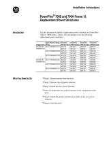
Frame 13 Drive Frame 14 1500A Drive Frame 14 Drive Above 1500A
Converter
Unit
Inverter
Unit
Converter
Unit
Inverter
Unit
Inverter
Unit
Converter
Unit
Inverter
Unit
Inverter
Unit
Converter
Unit
ATTENTION: To avoid an electric shock hazard, verify that the voltage on
the bus capacitors has discharged before performing any work on the
drive. Check the DC bus voltage at the Power Terminal Block by measuring
between the +DC and -DC terminals, between the +DC terminal and the
chassis, and between the -DC terminal and the chassis. The voltage must
be zero for all three measurements.
Remove power before making or breaking cable connections. When you
remove or insert a cable connector with power applied, an electrical arc
may occur. An electrical arc can cause personal injury or property damage
by:
sending an erroneous signal to your system’s field devices, causing
unintended machine motion
causing an explosion in a hazardous environment
Electrical arcing causes excessive wear to contacts on both the module
and its mating connector. Worn contacts may create electrical resistance.
L1 L2 L3
O
I
4 Rockwell Automation Publication PFLEX-IN027A-EN-P - July 2011
PowerFlex 700H and 700S AC Drives Frames 13 and 14 Main Fan Capacitor Replacement Kit
Step: 2 Remove the
Protective Covers
1. If you are replacing the fan capacitor on an inverter unit for an AC input
drive, skip this step and continue with step 2 below. If you are replacing the
fan capacitor on a converter unit or an inverter unit for a DC input drive,
complete the following steps:
a. For DC input drives with a precharge interlock, disconnect the input
wiring to the X50 terminal block on the control frame.
b. Loosen the two hexalobular screws that secure the control frame to the
enclosure and swing the control frame away from the converter unit.
2. Remove the four hexalobular screws that secure the air flow plate to the
drive enclosure and slide the plate off the drive.
Loosen two
screws and
swing control
frame out
If present, remove
wiring from X50
terminal block
Remove four screws and air flow plate
Converter unit
Inverter unit
Note: AC input drive shown
Rockwell Automation Publication PFLEX-IN027A-EN-P - July 2011 5
PowerFlex 700H and 700S AC Drives Frames 13 and 14 Main Fan Capacitor Replacement Kit
3. Remove the four POZIDRIV screws that secure the protective cover to
the unit being repaired and remove the cover. Tightening torque for re-
assembly is 1.5 N
m (13.3 lbin).
4. If necessary, remove the side protective cover.
DC BUS CONDUCTORS AND CAPACITORS
OPERATE AT HIGH VOLTAGE. REMOVE POWER
AND WAIT 5 MINUTES BEFORE SERVICING
DANGER
!
Remove four screws
and covers
Top two screws are
5 x 10 mm
Bottom two screws
are 5 x 16 mm
Remove side cover,
if necessary.
Inverter unit shown
6 Rockwell Automation Publication PFLEX-IN027A-EN-P - July 2011
PowerFlex 700H and 700S AC Drives Frames 13 and 14 Main Fan Capacitor Replacement Kit
Step: 3 Remove the
Existing Fan Capacitor
The procedures vary depending on whether you are replacing a main fan
capacitor on a converter or inverter unit.
If you are replacing a capacitor for a fan on the converter unit, continue
with Replacing the Fan Capacitor on the Converter Unit
below.
If you are replacing a capacitor for a fan on the inverter unit, continue with
Replacing the Fan Capacitor on the Inverter Unit
on page 11.
Replacing the Fan Capacitor on the Converter Unit
1. Remove the two fuses from the fuse holder.
2. Disconnect the +DC and -DC wires from the fan fuse holder.
3. Remove the M4 x 8 mm POZIDRIV screw that secures the fuse holder
assembly to the drive chassis and remove the fuse holder assembly.
Tightening torque for re-assembly is 3 N
m (26.5 lbin).
Remove fuses, +DC and -DC
wires, screw and fuse holder
Rockwell Automation Publication PFLEX-IN027A-EN-P - July 2011 7
PowerFlex 700H and 700S AC Drives Frames 13 and 14 Main Fan Capacitor Replacement Kit
4. Remove the four Phillips® head screws that secure the fan inverter
protection cover to the drive, and remove the cover. Tightening torque for
re-assembly is 0.9 N
m (8 lbin).
Remove screws
Remove screws
Remove cover
8 Rockwell Automation Publication PFLEX-IN027A-EN-P - July 2011
PowerFlex 700H and 700S AC Drives Frames 13 and 14 Main Fan Capacitor Replacement Kit
5. Disconnect the connector X3 from the fan inverter circuit board.
6. Cut the cable ties that secure the fan capacitor wires to the wire bundle.
7. Disconnect the fan capacitor wires from the connectors marked “Brown
and “Blue.
8. Unscrew and remove the existing fan capacitor from the inverter assembly.
Disconnect X3
Cut cable ties
Disconnect “Brown”
and “Blue” wires
Unscrew and
remove capacitor
Rockwell Automation Publication PFLEX-IN027A-EN-P - July 2011 9
PowerFlex 700H and 700S AC Drives Frames 13 and 14 Main Fan Capacitor Replacement Kit
9. Secure the fan capacitor bracket to the drive chassis using the M8 x 12 mm
hexagonal socket screw and spring washer provided as shown below.
Tightening torque is 20 N
m (178 lbin).
Fan capacitor bracket
Fan inverter
circuit board
Washer and screw
Side view of fan
capacitor bracket
Front of drive
Front view of drive and
fan capacitor bracket
10 Rockwell Automation Publication PFLEX-IN027A-EN-P - July 2011
PowerFlex 700H and 700S AC Drives Frames 13 and 14 Main Fan Capacitor Replacement Kit
10. Secure the new fan capacitor to the bracket using the M12 hexagonal nut
and lock washer provided. Tightening torque is 5 N
m (44.2 lbin).
11. Connect the new fan capacitor wires to the connectors marked “Brown
and “Blue.
12. Secure the fan capacitor wires to the fan wire bundle using cable ties.
13. Complete the remaining installation in the reverse order of removal as
detailed in the previous steps for the Converter Unit.
IMPORTANT
Verify that no wire shields are touching the sheet metal
on the drive chassis.
Fan capacitor
Lock washer
Hexagonal nut
Rockwell Automation Publication PFLEX-IN027A-EN-P - July 2011 11
PowerFlex 700H and 700S AC Drives Frames 13 and 14 Main Fan Capacitor Replacement Kit
Replacing the Fan Capacitor on the Inverter Unit
1. If you are replacing a fan capacitor on a PowerFlex 700H drive inverter
unit, continue with step 2 on page 12
. For PowerFlex 700S drives, if you
are replacing the fan capacitor on the V phase of the inverter unit,
complete steps a.…c.
a. Disconnect the bus connection cable from connector J2 and the motor
feedback connection cable from connector J1 on the voltage feedback
board.
b. Disconnect the fiber-optic cables from connectors J4 and J5 on the
voltage feedback board.
c. Remove the four POZIDRIV screws that secure the voltage feedback
board assembly to the fan housing and remove the assembly. Tightening
torque for re-assembly is 1.35 N
m (12 lbin).
IMPORTANT
Minimum inside bend radius for fiber-optic cable is 50 mm
(2 in.). Any bends with a shorter inside radius can
permanently damage the fiber-optic cable. Signal
attenuation increases with decreased inside bend radii.
J2
J1
J4
J5
Remove four screws
and assembly
12 Rockwell Automation Publication PFLEX-IN027A-EN-P - July 2011
PowerFlex 700H and 700S AC Drives Frames 13 and 14 Main Fan Capacitor Replacement Kit
2. If you are replacing the fan capacitor on the V phase power structure of the
inverter unit, cut the cable tie that secures the ASIC board fiber-optic
cable bundle to the fan housing (if present) and remove the fiber-optic
bundle and rubber grommet from the support bracket in order to allow
room for the fan housing to be removed from the unit.
3. Disconnect the fan inverter power supply wires from the bottom of the
fuse holder.
PowerFlex 700S drive shown
Cut cable tie
and remove
wire bundle and
grommet from
bracket
V phase power structure
Disconnect
wires from
bottom of
fuse holder
Rockwell Automation Publication PFLEX-IN027A-EN-P - July 2011 13
PowerFlex 700H and 700S AC Drives Frames 13 and 14 Main Fan Capacitor Replacement Kit
4. Disconnect the fan inverter connector from the connector on the support
bracket and pull the connector out of the sheet metal support bracket
using a pliers.
5. Remove the M8 x 20 mm hexagonal socket screw from the chassis in front
of the fan housing in order to allow room for the fan housing to be
removed from the unit. Tightening torque for re-assembly is 20 N
m (177
lb
in).
6. Remove the four POZIDRIV screws that secure the main fan housing to
the inverter assembly and remove the fan housing. Tightening torque for
re-assembly is 3.5 N
m (31 lbin).
Disconnect fan
cable
Remove screws
and fan housing
Using a pliers,
remove connector
from bracket
Remove screw from
chassis in front of
fan housing.
14 Rockwell Automation Publication PFLEX-IN027A-EN-P - July 2011
PowerFlex 700H and 700S AC Drives Frames 13 and 14 Main Fan Capacitor Replacement Kit
7. Carefully push the rubber grommet with the fan wire and connectors
through the hole in the drive chassis.
Remove grommet
and fan wires
from drive chassis
Rockwell Automation Publication PFLEX-IN027A-EN-P - July 2011 15
PowerFlex 700H and 700S AC Drives Frames 13 and 14 Main Fan Capacitor Replacement Kit
8. On the inside of the housing for the fan, cut the cable ties that secure the
fan inverter cable to the housing.
9. Remove the four M5 x 10 mm POZIDRIV screws that secure the fan
inverter assembly to the fan housing and, using the handle provided at the
base of the assembly, slide the fan inverter assembly out of the housing.
Tightening torque for re-assembly is 3.5 N
m (31 lbin).
Remove four screws
Cut cable ties
Use handle to remove fan
inverter assembly
16 Rockwell Automation Publication PFLEX-IN027A-EN-P - July 2011
PowerFlex 700H and 700S AC Drives Frames 13 and 14 Main Fan Capacitor Replacement Kit
10. Cut the cable ties that secure the fan capacitor wires to the wire bundle.
11. Disconnect the fan capacitor wires from the connectors marked “Brown
and “Blue.
12. Unscrew and remove the existing fan capacitor from the inverter assembly.
13. Secure the new fan capacitor to the bracket using the M12 hexagonal nut
and lock washer provided. Tightening torque is 5 N
m (44.2 lbin).
Disconnect “Brown”
and “Blue” wires
Unscrew and
remove capacitor
Remove cable tieRemove cable tie
Fan capacitor
Lock washer
Hex nut
Rockwell Automation Publication PFLEX-IN027A-EN-P - July 2011 17
PowerFlex 700H and 700S AC Drives Frames 13 and 14 Main Fan Capacitor Replacement Kit
14. Secure the fan capacitor bracket (and fan capacitor) to the fan inverter
assembly using the M8 x 12 mm hexagonal socket screw and spring washer
provided as shown below. Secure the capacitor in a position that allows the
maximum amount of clearance possible between the transformer and
capacitor, ensuring that they DO
NOT touch. Tightening torque is
20 N
m (178 lbin).
15. Connect the new fan capacitor wires to the connectors marked “Brown
and “Blue.
16. Secure the fan capacitor wires to the fan wire bundle using cable ties.
17. Complete the remaining installation in the reverse order of removal as
detailed in the previous steps for the Inverter Unit.
IMPORTANT
Verify that no wire shields are touching the sheet metal on the
fan inverter assembly.
IMPORTANT:
Verify that the fan
capacitor does not
touch the fan
transformer.
Secure fan bracket
(and capacitor) to
fan inverter
assembly using
hexagonal socket
screw and washer in
orientation shown
at left
Secure fan capacitor
wires to wire bundle
using cable ties
Connect fan capacitor
wires to “Brown” and
“Blue” connectors
Publication PFLEX-IN027A-EN-P – July 2011
Copyright © 2011 Rockwell Automation, Inc. All rights reserved. Printed in USA.
U.S. Allen-Bradley Drives Technical Support - Tel: (1) 262.512.8176, Fax: (1) 262.512.2222, E-mail: suppor[email protected].com, Online: www.ab.com/support/abdrives
www.rockwellautomation.com
Amer
i
cas:
Rockwell
Automation, 1201 South
Second
Street,
Milwaukee,
WI 53204
-
2496
USA,
Tel:
(1)
414.382.2000, Fax: (1)
414.382.4444
Europe
/
Middle East
/
Africa:
Rockwell
Automati
on,
Pegasus
Park,
De Kleetlaan 12a,
1831 Diegem, Belgium,
Tel: (32) 2 663
0600, Fax: (32) 2 663
0640
Asia Pacific: Rockwell Automation, Level 14,
Core F,
Cyberport
3, 100
Cyberport Road,
Hong Kong,
Tel: (852) 2887 4788, Fax:
(852) 2508
1846
Power,
Control
and
Information Solutions
Headquarters
*PN-117698*
PN-117698
  • Page 1 1
  • Page 2 2
  • Page 3 3
  • Page 4 4
  • Page 5 5
  • Page 6 6
  • Page 7 7
  • Page 8 8
  • Page 9 9
  • Page 10 10
  • Page 11 11
  • Page 12 12
  • Page 13 13
  • Page 14 14
  • Page 15 15
  • Page 16 16
  • Page 17 17
  • Page 18 18

Allen-Bradley PowerFlex 700H Installation Instructions Manual

Type
Installation Instructions Manual
This manual is also suitable for

Ask a question and I''ll find the answer in the document

Finding information in a document is now easier with AI