Page is loading ...

Reference Manual
PowerFlex 700S AC Drives Phase II Control
Firmware Revisions 1.xxx...4.xxx

Important User Information
Solid-state equipment has operational characteristics differing from those of electromechanical equipment. Safety
Guidelines for the Application, Installation and Maintenance of Solid State Controls (publication SGI-1.1
available from
your local Rockwell Automation sales office or online at http://www.rockwellautomation.com/literature/
) describes some
important differences between solid-state equipment and hard-wired electromechanical devices. Because of this difference,
and also because of the wide variety of uses for solid-state equipment, all persons responsible for applying this equipment
must satisfy themselves that each intended application of this equipment is acceptable.
In no event will Rockwell Automation, Inc. be responsible or liable for indirect or consequential damages resulting from
the use or application of this equipment.
The examples and diagrams in this manual are included solely for illustrative purposes. Because of the many variables and
requirements associated with any particular installation, Rockwell Automation, Inc. cannot assume responsibility or
liability for actual use based on the examples and diagrams.
No patent liability is assumed by Rockwell Automation, Inc. with respect to use of information, circuits, equipment, or
software described in this manual.
Reproduction of the contents of this manual, in whole or in part, without written permission of Rockwell Automation,
Inc., is prohibited.
Throughout this manual, when necessary, we use notes to make you aware of safety considerations.
Allen-Bradley, DriveExplorer, DriveExecutive, DriveLogix, PowerFlex, Rockwell Software, Rockwell Automation, Synchlink, and TechConnect are trademarks of Rockwell Automation, Inc.
Trademarks not belonging to Rockwell Automation are property of their respective companies.
WARNING: Identifies information about practices or circumstances that can cause an explosion in a hazardous
environment, which may lead to personal injury or death, property damage, or economic loss.
ATTENTION: Identifies information about practices or circumstances that can lead to personal injury or death,
property damage, or economic loss. Attentions help you identify a hazard, avoid a hazard, and recognize the
consequence
SHOCK HAZARD: Labels may be on or inside the equipment, for example, a drive or motor, to alert people that
dangerous voltage may be present.
BURN HAZARD: Labels may be on or inside the equipment, for example, a drive or motor, to alert people that
surfaces may reach dangerous temperatures.
IMPORTANT
Identifies information that is critical for successful application and understanding of the product.

Rockwell Automation Publication PFLEX-RM003E-EN-E - January 2011 3
Summary of Changes
This manual contains new and updated information.
New and Updated
Information
This table contains the changes made to this revision.
Topic Page
Removed content of previous Chapter 1 - Specifications and
Dimensions.
See the PowerFlex 700S AC Drives, Phase II Control Technical Data,
publication 20D-TD002 for the most current specifications and drive
dimension information.
NA
Updated all references to the PowerFlex 700S AC Drive Phase II
Control User Manual, publication 20D-UM006, to the following
publications as applicable:
• PowerFlex 700S AC Drive Phase II Control Programming Manual,
publication 20D-PM001
• PowerFlex 700S AC Drive Phase II Control Frames 1…6
Installation Instructions, publication 20D-IN024
• PowerFlex 700H and 700S Frame 9…14 Drives Installation
Manual, publication PFLEX-IN006
(Multiple pages)
Updated the Permanent Magnet Motor Control section to include
information on Heidenhain encoders.
70
Updated the “Ride Through Configuration” section to describe the
conditions that will cause the “RideThru” (F92) alarm to occur.
111

4 Rockwell Automation Publication PFLEX-RM003E-EN-E - January 2011
Summary of Changes

Rockwell Automation Publication PFLEX-RM003E-EN-E - January 2011 5
Table of Contents
Summary of Changes
New and Updated Information. . . . . . . . . . . . . . . . . . . . . . . . . . . . . . . . . . . . . . 3
Chapter 1
Detailed Drive Operation
Accel Time . . . . . . . . . . . . . . . . . . . . . . . . . . . . . . . . . . . . . . . . . . . . . . . . . . . . . . 13
Alarms . . . . . . . . . . . . . . . . . . . . . . . . . . . . . . . . . . . . . . . . . . . . . . . . . . . . . . . . . . 13
Configuration. . . . . . . . . . . . . . . . . . . . . . . . . . . . . . . . . . . . . . . . . . . . . . . . 14
Configuration Example . . . . . . . . . . . . . . . . . . . . . . . . . . . . . . . . . . . . . . . 14
Analog Inputs. . . . . . . . . . . . . . . . . . . . . . . . . . . . . . . . . . . . . . . . . . . . . . . . . . . . 14
Analog Input Specifications . . . . . . . . . . . . . . . . . . . . . . . . . . . . . . . . . . . 14
Analog Input Configuration. . . . . . . . . . . . . . . . . . . . . . . . . . . . . . . . . . . 14
Analog Input Loss Detection . . . . . . . . . . . . . . . . . . . . . . . . . . . . . . . . . . 16
Analog Outputs. . . . . . . . . . . . . . . . . . . . . . . . . . . . . . . . . . . . . . . . . . . . . . . . . . 17
Analog Output Specifications . . . . . . . . . . . . . . . . . . . . . . . . . . . . . . . . . 17
Analog Output Configuration. . . . . . . . . . . . . . . . . . . . . . . . . . . . . . . . . 17
Auto/Manual. . . . . . . . . . . . . . . . . . . . . . . . . . . . . . . . . . . . . . . . . . . . . . . . . . . . 18
Autotune. . . . . . . . . . . . . . . . . . . . . . . . . . . . . . . . . . . . . . . . . . . . . . . . . . . . . . . . 19
Autotune - Start-Up Menu. . . . . . . . . . . . . . . . . . . . . . . . . . . . . . . . . . . . 19
Motor Control . . . . . . . . . . . . . . . . . . . . . . . . . . . . . . . . . . . . . . . . . . . . . . . 19
Motor Data . . . . . . . . . . . . . . . . . . . . . . . . . . . . . . . . . . . . . . . . . . . . . . . . . . 19
Feedback Configuration . . . . . . . . . . . . . . . . . . . . . . . . . . . . . . . . . . . . . . 20
Power Circuit Test . . . . . . . . . . . . . . . . . . . . . . . . . . . . . . . . . . . . . . . . . . . 20
Direction Test . . . . . . . . . . . . . . . . . . . . . . . . . . . . . . . . . . . . . . . . . . . . . . . 20
Motor Tests. . . . . . . . . . . . . . . . . . . . . . . . . . . . . . . . . . . . . . . . . . . . . . . . . . 20
Inertia Test . . . . . . . . . . . . . . . . . . . . . . . . . . . . . . . . . . . . . . . . . . . . . . . . . . 21
Troubleshooting a “MC Commissn Fail” Fault during Autotune . 22
Auxiliary Power Supply . . . . . . . . . . . . . . . . . . . . . . . . . . . . . . . . . . . . . . . . . . . 22
Bus Regulation/Braking . . . . . . . . . . . . . . . . . . . . . . . . . . . . . . . . . . . . . . . . . . 22
Description . . . . . . . . . . . . . . . . . . . . . . . . . . . . . . . . . . . . . . . . . . . . . . . . . . 22
Technical Information. . . . . . . . . . . . . . . . . . . . . . . . . . . . . . . . . . . . . . . . 22
Bus Regulator/Braking Configuration. . . . . . . . . . . . . . . . . . . . . . . . . . 23
Cable, Control. . . . . . . . . . . . . . . . . . . . . . . . . . . . . . . . . . . . . . . . . . . . . . . . . . . 26
Cable, Lengths for Motors . . . . . . . . . . . . . . . . . . . . . . . . . . . . . . . . . . . . . . . . 26
Cable, Power . . . . . . . . . . . . . . . . . . . . . . . . . . . . . . . . . . . . . . . . . . . . . . . . . . . . 26
Cable Trays and Conduit . . . . . . . . . . . . . . . . . . . . . . . . . . . . . . . . . . . . . . . . . 27
Carrier (PWM) Frequency. . . . . . . . . . . . . . . . . . . . . . . . . . . . . . . . . . . . . . . . 27
CE Conformity . . . . . . . . . . . . . . . . . . . . . . . . . . . . . . . . . . . . . . . . . . . . . . . . . . 28
Common Bus Systems . . . . . . . . . . . . . . . . . . . . . . . . . . . . . . . . . . . . . . . . . . . . 28
Communications . . . . . . . . . . . . . . . . . . . . . . . . . . . . . . . . . . . . . . . . . . . . . . . . 28
ControlLogix System . . . . . . . . . . . . . . . . . . . . . . . . . . . . . . . . . . . . . . . . . 28
PLC 5 or SLC System. . . . . . . . . . . . . . . . . . . . . . . . . . . . . . . . . . . . . . . . . 30
Copy Cat. . . . . . . . . . . . . . . . . . . . . . . . . . . . . . . . . . . . . . . . . . . . . . . . . . . . . . . . 34
Current Limit . . . . . . . . . . . . . . . . . . . . . . . . . . . . . . . . . . . . . . . . . . . . . . . . . . . 35
Datalinks . . . . . . . . . . . . . . . . . . . . . . . . . . . . . . . . . . . . . . . . . . . . . . . . . . . . . . . . 35
Configuring Datalinks . . . . . . . . . . . . . . . . . . . . . . . . . . . . . . . . . . . . . . . . 35
Decel Time . . . . . . . . . . . . . . . . . . . . . . . . . . . . . . . . . . . . . . . . . . . . . . . . . . . . . . 37

6 Rockwell Automation Publication PFLEX-RM003E-EN-E - January 2011
Table of Contents
Digital Inputs . . . . . . . . . . . . . . . . . . . . . . . . . . . . . . . . . . . . . . . . . . . . . . . . . . . . 37
Technical Information . . . . . . . . . . . . . . . . . . . . . . . . . . . . . . . . . . . . . . . . 37
Digital Input Configuration . . . . . . . . . . . . . . . . . . . . . . . . . . . . . . . . . . . 38
Digital Input Status Bits. . . . . . . . . . . . . . . . . . . . . . . . . . . . . . . . . . . . . . . 39
Digital Outputs . . . . . . . . . . . . . . . . . . . . . . . . . . . . . . . . . . . . . . . . . . . . . . . . . . 39
Technical Information . . . . . . . . . . . . . . . . . . . . . . . . . . . . . . . . . . . . . . . . 39
Digital Output Configuration . . . . . . . . . . . . . . . . . . . . . . . . . . . . . . . . . 40
Digital Output Status Bits . . . . . . . . . . . . . . . . . . . . . . . . . . . . . . . . . . . . . 40
Digital Output On/Off Delay Timers . . . . . . . . . . . . . . . . . . . . . . . . . . 41
Direction Control and Bipolar Reference. . . . . . . . . . . . . . . . . . . . . . . . . . . 41
Drive Peripheral Interface (DPI). . . . . . . . . . . . . . . . . . . . . . . . . . . . . . . . . . . 42
Client/Server. . . . . . . . . . . . . . . . . . . . . . . . . . . . . . . . . . . . . . . . . . . . . . . . . 43
Producer/Consumer Operation Overview . . . . . . . . . . . . . . . . . . . . . . 43
Peer-to-Peer Operation. . . . . . . . . . . . . . . . . . . . . . . . . . . . . . . . . . . . . . . . 43
DriveLogix. . . . . . . . . . . . . . . . . . . . . . . . . . . . . . . . . . . . . . . . . . . . . . . . . . . . . . . 45
Drive Overload. . . . . . . . . . . . . . . . . . . . . . . . . . . . . . . . . . . . . . . . . . . . . . . . . . . 45
Theory of Operation . . . . . . . . . . . . . . . . . . . . . . . . . . . . . . . . . . . . . . . . . . 45
Drive Over Temperature
(Frame 9 Only). . . . . . . . . . . . . . . . . . . . . . . . . . . . . . . . . . . . . . . . . . . . . . . . . . . 46
Droop . . . . . . . . . . . . . . . . . . . . . . . . . . . . . . . . . . . . . . . . . . . . . . . . . . . . . . . . . . . 47
Dynamic Braking. . . . . . . . . . . . . . . . . . . . . . . . . . . . . . . . . . . . . . . . . . . . . . . . . 47
Efficiency . . . . . . . . . . . . . . . . . . . . . . . . . . . . . . . . . . . . . . . . . . . . . . . . . . . . . . . . 47
Electronic Gearing. . . . . . . . . . . . . . . . . . . . . . . . . . . . . . . . . . . . . . . . . . . . . . . . 48
Faults. . . . . . . . . . . . . . . . . . . . . . . . . . . . . . . . . . . . . . . . . . . . . . . . . . . . . . . . . . . . 48
Configuration . . . . . . . . . . . . . . . . . . . . . . . . . . . . . . . . . . . . . . . . . . . . . . . . 48
Configuration Example . . . . . . . . . . . . . . . . . . . . . . . . . . . . . . . . . . . . . . . 48
Filters . . . . . . . . . . . . . . . . . . . . . . . . . . . . . . . . . . . . . . . . . . . . . . . . . . . . . . . . . . . 48
Key Words . . . . . . . . . . . . . . . . . . . . . . . . . . . . . . . . . . . . . . . . . . . . . . . . . . . 48
Nomenclature . . . . . . . . . . . . . . . . . . . . . . . . . . . . . . . . . . . . . . . . . . . . . . . 49
Low Pass Filter . . . . . . . . . . . . . . . . . . . . . . . . . . . . . . . . . . . . . . . . . . . . . . . 49
Second Order Low Pass Filter. . . . . . . . . . . . . . . . . . . . . . . . . . . . . . . . . . 49
Lead-Lag Filter . . . . . . . . . . . . . . . . . . . . . . . . . . . . . . . . . . . . . . . . . . . . . . . 50
Notch Filter . . . . . . . . . . . . . . . . . . . . . . . . . . . . . . . . . . . . . . . . . . . . . . . . . . 53
Conclusion. . . . . . . . . . . . . . . . . . . . . . . . . . . . . . . . . . . . . . . . . . . . . . . . . . . 55
Firmware Functions . . . . . . . . . . . . . . . . . . . . . . . . . . . . . . . . . . . . . . . . . . . . . . 56
Flying Start . . . . . . . . . . . . . . . . . . . . . . . . . . . . . . . . . . . . . . . . . . . . . . . . . . . . . . 56
Configuration . . . . . . . . . . . . . . . . . . . . . . . . . . . . . . . . . . . . . . . . . . . . . . . . 57
Friction Compensation . . . . . . . . . . . . . . . . . . . . . . . . . . . . . . . . . . . . . . . . . . . 57
Fuses and Circuit Breakers . . . . . . . . . . . . . . . . . . . . . . . . . . . . . . . . . . . . . . . . 58
Grounding, General . . . . . . . . . . . . . . . . . . . . . . . . . . . . . . . . . . . . . . . . . . . . . . 58
HIM Memory. . . . . . . . . . . . . . . . . . . . . . . . . . . . . . . . . . . . . . . . . . . . . . . . . . . . 58
HIM Operations . . . . . . . . . . . . . . . . . . . . . . . . . . . . . . . . . . . . . . . . . . . . . . . . . 59
The User Display . . . . . . . . . . . . . . . . . . . . . . . . . . . . . . . . . . . . . . . . . . . . . 59
Indexer . . . . . . . . . . . . . . . . . . . . . . . . . . . . . . . . . . . . . . . . . . . . . . . . . . . . . . . . . . 59
Configuring the Indexer. . . . . . . . . . . . . . . . . . . . . . . . . . . . . . . . . . . . . . . 60
Inertia Adaption . . . . . . . . . . . . . . . . . . . . . . . . . . . . . . . . . . . . . . . . . . . . . . . . . 61

Rockwell Automation Publication PFLEX-RM003E-EN-E - January 2011 7
Table of Contents
Configuration. . . . . . . . . . . . . . . . . . . . . . . . . . . . . . . . . . . . . . . . . . . . . . . . 62
Inertia Compensation . . . . . . . . . . . . . . . . . . . . . . . . . . . . . . . . . . . . . . . . . . . . 62
Input Devices . . . . . . . . . . . . . . . . . . . . . . . . . . . . . . . . . . . . . . . . . . . . . . . . . . . . 63
Contactors. . . . . . . . . . . . . . . . . . . . . . . . . . . . . . . . . . . . . . . . . . . . . . . . . . . 63
Circuit Breakers/Fuses. . . . . . . . . . . . . . . . . . . . . . . . . . . . . . . . . . . . . . . . 63
Filters EMC . . . . . . . . . . . . . . . . . . . . . . . . . . . . . . . . . . . . . . . . . . . . . . . . . 63
Input Modes. . . . . . . . . . . . . . . . . . . . . . . . . . . . . . . . . . . . . . . . . . . . . . . . . . . . . 63
Input Power Conditioning. . . . . . . . . . . . . . . . . . . . . . . . . . . . . . . . . . . . . . . . 63
IT Protection . . . . . . . . . . . . . . . . . . . . . . . . . . . . . . . . . . . . . . . . . . . . . . . . . . . . 64
Jog . . . . . . . . . . . . . . . . . . . . . . . . . . . . . . . . . . . . . . . . . . . . . . . . . . . . . . . . . . . . . . 65
Limit Generator. . . . . . . . . . . . . . . . . . . . . . . . . . . . . . . . . . . . . . . . . . . . . . . . . . 65
Links. . . . . . . . . . . . . . . . . . . . . . . . . . . . . . . . . . . . . . . . . . . . . . . . . . . . . . . . . . . . 66
Using a HIM. . . . . . . . . . . . . . . . . . . . . . . . . . . . . . . . . . . . . . . . . . . . . . . . . 66
Using DriveExecutive. . . . . . . . . . . . . . . . . . . . . . . . . . . . . . . . . . . . . . . . . 67
Masks . . . . . . . . . . . . . . . . . . . . . . . . . . . . . . . . . . . . . . . . . . . . . . . . . . . . . . . . . . . 68
Motor Control Mode . . . . . . . . . . . . . . . . . . . . . . . . . . . . . . . . . . . . . . . . . . . . 69
Field Oriented Control . . . . . . . . . . . . . . . . . . . . . . . . . . . . . . . . . . . . . . . 69
Permanent Magnet Control . . . . . . . . . . . . . . . . . . . . . . . . . . . . . . . . . . . 70
Volts/Hertz Control - v2.003 and later. . . . . . . . . . . . . . . . . . . . . . . . . 70
Motor Nameplate . . . . . . . . . . . . . . . . . . . . . . . . . . . . . . . . . . . . . . . . . . . . . . . . 71
Motor Overload . . . . . . . . . . . . . . . . . . . . . . . . . . . . . . . . . . . . . . . . . . . . . . . . . 72
Normal Duty . . . . . . . . . . . . . . . . . . . . . . . . . . . . . . . . . . . . . . . . . . . . . . . . 72
Heavy Duty . . . . . . . . . . . . . . . . . . . . . . . . . . . . . . . . . . . . . . . . . . . . . . . . . . 72
Motor Overload Memory Retention Per 2005 NEC. . . . . . . . . . . . . 73
Motor Start and Stop Precautions . . . . . . . . . . . . . . . . . . . . . . . . . . . . . . . . . 74
Input Contactor Precautions . . . . . . . . . . . . . . . . . . . . . . . . . . . . . . . . . . 74
Output Contactor Precaution . . . . . . . . . . . . . . . . . . . . . . . . . . . . . . . . 74
Mounting . . . . . . . . . . . . . . . . . . . . . . . . . . . . . . . . . . . . . . . . . . . . . . . . . . . . . . . 74
Output Devices . . . . . . . . . . . . . . . . . . . . . . . . . . . . . . . . . . . . . . . . . . . . . . . . . . 75
Drive Output Disconnection . . . . . . . . . . . . . . . . . . . . . . . . . . . . . . . . . 75
Cable Termination . . . . . . . . . . . . . . . . . . . . . . . . . . . . . . . . . . . . . . . . . . . 75
Output Reactor . . . . . . . . . . . . . . . . . . . . . . . . . . . . . . . . . . . . . . . . . . . . . . 75
Output Display . . . . . . . . . . . . . . . . . . . . . . . . . . . . . . . . . . . . . . . . . . . . . . . . . . 76
Output Current (Parameter 308) . . . . . . . . . . . . . . . . . . . . . . . . . . . . . . 76
Output Freq (Parameter 310) . . . . . . . . . . . . . . . . . . . . . . . . . . . . . . . . . 76
Output Power (Parameter 311). . . . . . . . . . . . . . . . . . . . . . . . . . . . . . . . 76
Output Voltage (Parameter 307) . . . . . . . . . . . . . . . . . . . . . . . . . . . . . . 76
Overspeed Limit . . . . . . . . . . . . . . . . . . . . . . . . . . . . . . . . . . . . . . . . . . . . . . . . . 76
Owners. . . . . . . . . . . . . . . . . . . . . . . . . . . . . . . . . . . . . . . . . . . . . . . . . . . . . . . . . . 77
Exclusive Ownership. . . . . . . . . . . . . . . . . . . . . . . . . . . . . . . . . . . . . . . . . . 77
Non-Exclusive Ownership . . . . . . . . . . . . . . . . . . . . . . . . . . . . . . . . . . . . 77
Peak Detect. . . . . . . . . . . . . . . . . . . . . . . . . . . . . . . . . . . . . . . . . . . . . . . . . . . . . . 79
Permanent Magnet Motors . . . . . . . . . . . . . . . . . . . . . . . . . . . . . . . . . . . . . . . 80
Phase Locked Loop. . . . . . . . . . . . . . . . . . . . . . . . . . . . . . . . . . . . . . . . . . . . . . . 80
Position Reference. . . . . . . . . . . . . . . . . . . . . . . . . . . . . . . . . . . . . . . . . . . . 81
Speed Reference (Feed Forward). . . . . . . . . . . . . . . . . . . . . . . . . . . . . . . 81

8 Rockwell Automation Publication PFLEX-RM003E-EN-E - January 2011
Table of Contents
Noise Filtering. . . . . . . . . . . . . . . . . . . . . . . . . . . . . . . . . . . . . . . . . . . . . . . . 82
Virtual Encoder. . . . . . . . . . . . . . . . . . . . . . . . . . . . . . . . . . . . . . . . . . . . . . . 82
Electronic Gear Ratio . . . . . . . . . . . . . . . . . . . . . . . . . . . . . . . . . . . . . . . . . 83
Output Section . . . . . . . . . . . . . . . . . . . . . . . . . . . . . . . . . . . . . . . . . . . . . . . 83
Point to Point Motion Planner . . . . . . . . . . . . . . . . . . . . . . . . . . . . . . . . . . . . 86
Configuration . . . . . . . . . . . . . . . . . . . . . . . . . . . . . . . . . . . . . . . . . . . . . . . . 86
Profile Generator . . . . . . . . . . . . . . . . . . . . . . . . . . . . . . . . . . . . . . . . . . . . . 88
Speed Output (Feed-Forward) . . . . . . . . . . . . . . . . . . . . . . . . . . . . . . . . . 88
Position Output . . . . . . . . . . . . . . . . . . . . . . . . . . . . . . . . . . . . . . . . . . . . . . 89
Position Loop - Follower (Electronic Gearing) . . . . . . . . . . . . . . . . . . . . . . 90
Overview. . . . . . . . . . . . . . . . . . . . . . . . . . . . . . . . . . . . . . . . . . . . . . . . . . . . . 90
Speed Reference Selection . . . . . . . . . . . . . . . . . . . . . . . . . . . . . . . . . . . . . 91
Speed Reference Ramp . . . . . . . . . . . . . . . . . . . . . . . . . . . . . . . . . . . . . . . . 92
Enabling the Position Loop. . . . . . . . . . . . . . . . . . . . . . . . . . . . . . . . . . . . 92
Position Reference Selection . . . . . . . . . . . . . . . . . . . . . . . . . . . . . . . . . . . 92
Setting the Electronic Gear Ratio and Speed Reference Scaling. . . . 93
Position Offset . . . . . . . . . . . . . . . . . . . . . . . . . . . . . . . . . . . . . . . . . . . . . . . 94
Position Loop Output Limits . . . . . . . . . . . . . . . . . . . . . . . . . . . . . . . . . . 94
Tuning Tips. . . . . . . . . . . . . . . . . . . . . . . . . . . . . . . . . . . . . . . . . . . . . . . . . . 95
Jogging a Position Follower Independent from the Master. . . . . . . . 95
Position Loop - In Position Detect . . . . . . . . . . . . . . . . . . . . . . . . . . . . . . . . . 96
Position Loop - Point to Point. . . . . . . . . . . . . . . . . . . . . . . . . . . . . . . . . . . . . 96
Overview. . . . . . . . . . . . . . . . . . . . . . . . . . . . . . . . . . . . . . . . . . . . . . . . . . . . . 96
Speed Reference Selection . . . . . . . . . . . . . . . . . . . . . . . . . . . . . . . . . . . . . 97
Enabling the Position Loop. . . . . . . . . . . . . . . . . . . . . . . . . . . . . . . . . . . . 97
Position Reference Selection . . . . . . . . . . . . . . . . . . . . . . . . . . . . . . . . . . . 97
Position Reference Scaling. . . . . . . . . . . . . . . . . . . . . . . . . . . . . . . . . . . . . 98
Position Offset . . . . . . . . . . . . . . . . . . . . . . . . . . . . . . . . . . . . . . . . . . . . . . . 98
Point to Point Acceleration and Deceleration . . . . . . . . . . . . . . . . . . . 99
Position Loop Output Limits . . . . . . . . . . . . . . . . . . . . . . . . . . . . . . . . . . 99
Tuning Tips. . . . . . . . . . . . . . . . . . . . . . . . . . . . . . . . . . . . . . . . . . . . . . . . . . 99
Jogging. . . . . . . . . . . . . . . . . . . . . . . . . . . . . . . . . . . . . . . . . . . . . . . . . . . . . . 100
Point to Point Re-Reference . . . . . . . . . . . . . . . . . . . . . . . . . . . . . . . . . . 100
Absolute Point to Point Positioning: . . . . . . . . . . . . . . . . . . . . . . . . . . 101
Example to Control the Point to Point Position with Digital Inputs: .
101
Position Loop - Position Watch . . . . . . . . . . . . . . . . . . . . . . . . . . . . . . . . . . 104
Position Loop - Registration. . . . . . . . . . . . . . . . . . . . . . . . . . . . . . . . . . . . . . 105
Encoder 0 and 1 Registration . . . . . . . . . . . . . . . . . . . . . . . . . . . . . . . . . 105
Feedback Option 0 and 1 Registration . . . . . . . . . . . . . . . . . . . . . . . . . 108
Power Loss/Ride Through . . . . . . . . . . . . . . . . . . . . . . . . . . . . . . . . . . . . . . . 109
Precharge Frames 1…4 . . . . . . . . . . . . . . . . . . . . . . . . . . . . . . . . . . . . . . . 110
Precharge Frames 5 and Up - AC Input “Stand Alone Drives” . . . 110
Precharge Frames 5 and Up - DC Input “Common Bus Drives” . 110
Ride Through Operation . . . . . . . . . . . . . . . . . . . . . . . . . . . . . . . . . . . . . 111
Ride Through Configuration . . . . . . . . . . . . . . . . . . . . . . . . . . . . . . . . . 111

Rockwell Automation Publication PFLEX-RM003E-EN-E - January 2011 9
Table of Contents
Ride Through Timeout Fault. . . . . . . . . . . . . . . . . . . . . . . . . . . . . . . . . 112
Precharge Operation. . . . . . . . . . . . . . . . . . . . . . . . . . . . . . . . . . . . . . . . . 112
Precharge Timeout Fault. . . . . . . . . . . . . . . . . . . . . . . . . . . . . . . . . . . . . 114
External Precharge. . . . . . . . . . . . . . . . . . . . . . . . . . . . . . . . . . . . . . . . . . . 115
Precharge Staging. . . . . . . . . . . . . . . . . . . . . . . . . . . . . . . . . . . . . . . . . . . . 116
Motor Sim Mode. . . . . . . . . . . . . . . . . . . . . . . . . . . . . . . . . . . . . . . . . . . . 116
External Power Supply . . . . . . . . . . . . . . . . . . . . . . . . . . . . . . . . . . . . . . . 116
Preset Speeds . . . . . . . . . . . . . . . . . . . . . . . . . . . . . . . . . . . . . . . . . . . . . . . . . . . 116
Process PI Loop . . . . . . . . . . . . . . . . . . . . . . . . . . . . . . . . . . . . . . . . . . . . . . . . . 117
Process PI Reference and Feedback. . . . . . . . . . . . . . . . . . . . . . . . . . . . 117
Process PI Regulator . . . . . . . . . . . . . . . . . . . . . . . . . . . . . . . . . . . . . . . . . 117
Process PI Limits . . . . . . . . . . . . . . . . . . . . . . . . . . . . . . . . . . . . . . . . . . . . 118
Process PI Output . . . . . . . . . . . . . . . . . . . . . . . . . . . . . . . . . . . . . . . . . . . 118
Pulse Elimination Technique (PET) . . . . . . . . . . . . . . . . . . . . . . . . . . . . . . 119
Reflected Wave . . . . . . . . . . . . . . . . . . . . . . . . . . . . . . . . . . . . . . . . . . . . . . . . . 119
RFI Filter Grounding. . . . . . . . . . . . . . . . . . . . . . . . . . . . . . . . . . . . . . . . . . . . 120
S-Curve . . . . . . . . . . . . . . . . . . . . . . . . . . . . . . . . . . . . . . . . . . . . . . . . . . . . . . . . 120
Security . . . . . . . . . . . . . . . . . . . . . . . . . . . . . . . . . . . . . . . . . . . . . . . . . . . . . . . . 121
Communication Peripherals. . . . . . . . . . . . . . . . . . . . . . . . . . . . . . . . . . 121
Software Tools . . . . . . . . . . . . . . . . . . . . . . . . . . . . . . . . . . . . . . . . . . . . . . 121
Sensorless Operation . . . . . . . . . . . . . . . . . . . . . . . . . . . . . . . . . . . . . . . . . . . . 122
Slip Compensation . . . . . . . . . . . . . . . . . . . . . . . . . . . . . . . . . . . . . . . . . . 122
Sensorless Gains . . . . . . . . . . . . . . . . . . . . . . . . . . . . . . . . . . . . . . . . . . . . . 122
Sensorless Operation in Frames 9 and Up Drives . . . . . . . . . . . . . . . 123
Sensorless Flying Start . . . . . . . . . . . . . . . . . . . . . . . . . . . . . . . . . . . . . . . 123
Skip Speeds . . . . . . . . . . . . . . . . . . . . . . . . . . . . . . . . . . . . . . . . . . . . . . . . . . . . . 123
Configuration: . . . . . . . . . . . . . . . . . . . . . . . . . . . . . . . . . . . . . . . . . . . . . . 123
Slip Compensation . . . . . . . . . . . . . . . . . . . . . . . . . . . . . . . . . . . . . . . . . . . . . . 126
Slip Compensation Configuration . . . . . . . . . . . . . . . . . . . . . . . . . . . . 126
Speed Control, Speed Mode, Speed Regulation . . . . . . . . . . . . . . . . . . . . 127
Speed/Position Feedback . . . . . . . . . . . . . . . . . . . . . . . . . . . . . . . . . . . . . . . . 128
Feedback Device. . . . . . . . . . . . . . . . . . . . . . . . . . . . . . . . . . . . . . . . . . . . . 128
Encoder . . . . . . . . . . . . . . . . . . . . . . . . . . . . . . . . . . . . . . . . . . . . . . . . . . . . 128
Linear Feedback Devices . . . . . . . . . . . . . . . . . . . . . . . . . . . . . . . . . . . . . 131
FIR Filter . . . . . . . . . . . . . . . . . . . . . . . . . . . . . . . . . . . . . . . . . . . . . . . . . . . 132
Sensorless . . . . . . . . . . . . . . . . . . . . . . . . . . . . . . . . . . . . . . . . . . . . . . . . . . . 132
Motor Simulator . . . . . . . . . . . . . . . . . . . . . . . . . . . . . . . . . . . . . . . . . . . . 133
Feedback Option Cards. . . . . . . . . . . . . . . . . . . . . . . . . . . . . . . . . . . . . . 133
Motor Speed Feedback and Scaled Speed Feedback . . . . . . . . . . . . . 140
Position Feedback . . . . . . . . . . . . . . . . . . . . . . . . . . . . . . . . . . . . . . . . . . . 141
Speed Feedback Loss Ride Through . . . . . . . . . . . . . . . . . . . . . . . . . . . 141
Speed Reference. . . . . . . . . . . . . . . . . . . . . . . . . . . . . . . . . . . . . . . . . . . . . . . . . 145
Speed Reference Selection . . . . . . . . . . . . . . . . . . . . . . . . . . . . . . . . . . . . 145
Speed Reference Scaling. . . . . . . . . . . . . . . . . . . . . . . . . . . . . . . . . . . . . . 146
Jog Reference . . . . . . . . . . . . . . . . . . . . . . . . . . . . . . . . . . . . . . . . . . . . . . . 147
Direction Control and Bipolar Reference. . . . . . . . . . . . . . . . . . . . . . 147

10 Rockwell Automation Publication PFLEX-RM003E-EN-E - January 2011
Table of Contents
Speed Reference Limits. . . . . . . . . . . . . . . . . . . . . . . . . . . . . . . . . . . . . . . 147
Stop Command . . . . . . . . . . . . . . . . . . . . . . . . . . . . . . . . . . . . . . . . . . . . . 148
Accel/Decel Ramp and S-Curve. . . . . . . . . . . . . . . . . . . . . . . . . . . . . . . 148
Speed Reference Bypass and Delayed Speed Reference. . . . . . . . . . . 149
Inertia Compensation. . . . . . . . . . . . . . . . . . . . . . . . . . . . . . . . . . . . . . . . 149
Friction Compensation . . . . . . . . . . . . . . . . . . . . . . . . . . . . . . . . . . . . . . 150
Virtual Encoder. . . . . . . . . . . . . . . . . . . . . . . . . . . . . . . . . . . . . . . . . . . . . . 150
Speed Reference Filter. . . . . . . . . . . . . . . . . . . . . . . . . . . . . . . . . . . . . . . . 151
Speed Reference Scaling . . . . . . . . . . . . . . . . . . . . . . . . . . . . . . . . . . . . . . 151
Speed Trim 1 . . . . . . . . . . . . . . . . . . . . . . . . . . . . . . . . . . . . . . . . . . . . . . . . 151
Speed PI Regulator . . . . . . . . . . . . . . . . . . . . . . . . . . . . . . . . . . . . . . . . . . . . . . 152
Speed Trim. . . . . . . . . . . . . . . . . . . . . . . . . . . . . . . . . . . . . . . . . . . . . . . . . . 152
Autotune Speed Reference. . . . . . . . . . . . . . . . . . . . . . . . . . . . . . . . . . . . 153
Speed Reference Limits. . . . . . . . . . . . . . . . . . . . . . . . . . . . . . . . . . . . . . . 153
Current Limit Stop . . . . . . . . . . . . . . . . . . . . . . . . . . . . . . . . . . . . . . . . . . 154
Speed Error . . . . . . . . . . . . . . . . . . . . . . . . . . . . . . . . . . . . . . . . . . . . . . . . . 154
Servo Lock . . . . . . . . . . . . . . . . . . . . . . . . . . . . . . . . . . . . . . . . . . . . . . . . . . 154
Speed Regulator Gains . . . . . . . . . . . . . . . . . . . . . . . . . . . . . . . . . . . . . . . 155
Speed Regulation Anti-Backup. . . . . . . . . . . . . . . . . . . . . . . . . . . . . . . . 155
Proportional Gain . . . . . . . . . . . . . . . . . . . . . . . . . . . . . . . . . . . . . . . . . . . 156
Integral Gain . . . . . . . . . . . . . . . . . . . . . . . . . . . . . . . . . . . . . . . . . . . . . . . . 157
Droop . . . . . . . . . . . . . . . . . . . . . . . . . . . . . . . . . . . . . . . . . . . . . . . . . . . . . . 157
Speed Regulator Output Limits . . . . . . . . . . . . . . . . . . . . . . . . . . . . . . . 157
Speed Regulator Output Filter . . . . . . . . . . . . . . . . . . . . . . . . . . . . . . . . 158
Speed Regulator Tuning . . . . . . . . . . . . . . . . . . . . . . . . . . . . . . . . . . . . . . . . . 158
Basic Tuning with a Gear Box or Belt. . . . . . . . . . . . . . . . . . . . . . . . . . 158
Advanced Tuning for the Speed Regulator with Gearbox or Belt . 160
Speed/Torque Mode Select. . . . . . . . . . . . . . . . . . . . . . . . . . . . . . . . . . . . . . . 161
Zero Torque Mode . . . . . . . . . . . . . . . . . . . . . . . . . . . . . . . . . . . . . . . . . . 163
Speed Regulation Mode . . . . . . . . . . . . . . . . . . . . . . . . . . . . . . . . . . . . . . 163
Torque Regulation Mode. . . . . . . . . . . . . . . . . . . . . . . . . . . . . . . . . . . . . 164
Min Speed / Torque Mode and Max Speed / Torque Mode . . . . . 164
Sum Speed / Torque Mode . . . . . . . . . . . . . . . . . . . . . . . . . . . . . . . . . . . 165
Speed Limited Adjustable Torque (SLAT) Min Mode and SLAT Max
Mode . . . . . . . . . . . . . . . . . . . . . . . . . . . . . . . . . . . . . . . . . . . . . . . . . . . . . . . 165
Standalone Drive Homing without DriveLogix . . . . . . . . . . . . . . . . . . . . 170
Overview. . . . . . . . . . . . . . . . . . . . . . . . . . . . . . . . . . . . . . . . . . . . . . . . . . . . 170
Homing Sequence of Operation Descriptions . . . . . . . . . . . . . . . . . . 170
Configuration . . . . . . . . . . . . . . . . . . . . . . . . . . . . . . . . . . . . . . . . . . . . . . . 173
Homing Status . . . . . . . . . . . . . . . . . . . . . . . . . . . . . . . . . . . . . . . . . . . . . . 175
Optional Features. . . . . . . . . . . . . . . . . . . . . . . . . . . . . . . . . . . . . . . . . . . . 175
Start Inhibits. . . . . . . . . . . . . . . . . . . . . . . . . . . . . . . . . . . . . . . . . . . . . . . . . . . . 176
Start and Stop Modes . . . . . . . . . . . . . . . . . . . . . . . . . . . . . . . . . . . . . . . . . . . . 176
Configuring the Start and Stop for 3-Wire Control (Momentary Start
and Stop) . . . . . . . . . . . . . . . . . . . . . . . . . . . . . . . . . . . . . . . . . . . . . . . . . . . 177

Rockwell Automation Publication PFLEX-RM003E-EN-E - January 2011 11
Table of Contents
Configuring the Start and Stop for 2-Wire Control (Maintained Start
and Stop) . . . . . . . . . . . . . . . . . . . . . . . . . . . . . . . . . . . . . . . . . . . . . . . . . . . 178
Start-Up. . . . . . . . . . . . . . . . . . . . . . . . . . . . . . . . . . . . . . . . . . . . . . . . . . . . . . . . 179
Stop Modes. . . . . . . . . . . . . . . . . . . . . . . . . . . . . . . . . . . . . . . . . . . . . . . . . . . . . 179
SynchLink. . . . . . . . . . . . . . . . . . . . . . . . . . . . . . . . . . . . . . . . . . . . . . . . . . . . . . 180
SynchLink Configuration . . . . . . . . . . . . . . . . . . . . . . . . . . . . . . . . . . . . 180
SynchLink Direct Data . . . . . . . . . . . . . . . . . . . . . . . . . . . . . . . . . . . . . . 181
Multiply Block . . . . . . . . . . . . . . . . . . . . . . . . . . . . . . . . . . . . . . . . . . . . . . 183
Buffered Data . . . . . . . . . . . . . . . . . . . . . . . . . . . . . . . . . . . . . . . . . . . . . . . 185
SynchLink Diagnostics. . . . . . . . . . . . . . . . . . . . . . . . . . . . . . . . . . . . . . . 185
Speed Synchronization Example . . . . . . . . . . . . . . . . . . . . . . . . . . . . . . 187
SynchLink Axis Follower Selection for DriveLogix Feedback Only
Axis . . . . . . . . . . . . . . . . . . . . . . . . . . . . . . . . . . . . . . . . . . . . . . . . . . . . . . . . 190
Reset SynchLink . . . . . . . . . . . . . . . . . . . . . . . . . . . . . . . . . . . . . . . . . . . . 191
Sync Generator . . . . . . . . . . . . . . . . . . . . . . . . . . . . . . . . . . . . . . . . . . . . . . . . . 191
Configuration. . . . . . . . . . . . . . . . . . . . . . . . . . . . . . . . . . . . . . . . . . . . . . . 191
Task Time. . . . . . . . . . . . . . . . . . . . . . . . . . . . . . . . . . . . . . . . . . . . . . . . . . . . . . 192
Test Points . . . . . . . . . . . . . . . . . . . . . . . . . . . . . . . . . . . . . . . . . . . . . . . . . . . . . 192
Thermal Regulator . . . . . . . . . . . . . . . . . . . . . . . . . . . . . . . . . . . . . . . . . . . . . . 192
Time Function Generator . . . . . . . . . . . . . . . . . . . . . . . . . . . . . . . . . . . . . . . 193
Torque Reference . . . . . . . . . . . . . . . . . . . . . . . . . . . . . . . . . . . . . . . . . . . . . . . 193
Torque Reference Input. . . . . . . . . . . . . . . . . . . . . . . . . . . . . . . . . . . . . . 193
Trending . . . . . . . . . . . . . . . . . . . . . . . . . . . . . . . . . . . . . . . . . . . . . . . . . . . . . . . 194
Configuration. . . . . . . . . . . . . . . . . . . . . . . . . . . . . . . . . . . . . . . . . . . . . . . 194
Ungrounded, Unbalanced or High Resistive Ground Installations. . . 196
User Functions. . . . . . . . . . . . . . . . . . . . . . . . . . . . . . . . . . . . . . . . . . . . . . . . . . 197
Bit Swap . . . . . . . . . . . . . . . . . . . . . . . . . . . . . . . . . . . . . . . . . . . . . . . . . . . . 197
MOP. . . . . . . . . . . . . . . . . . . . . . . . . . . . . . . . . . . . . . . . . . . . . . . . . . . . . . . 198
MOP Configuration. . . . . . . . . . . . . . . . . . . . . . . . . . . . . . . . . . . . . . . . . 199
Controlling the MOP from Digital Inputs: . . . . . . . . . . . . . . . . . . . . 200
Controlling the MOP from a Network or DriveLogix . . . . . . . . . . 200
Selector Switches . . . . . . . . . . . . . . . . . . . . . . . . . . . . . . . . . . . . . . . . . . . . 200
DInt to Real and Real to DInt Converters . . . . . . . . . . . . . . . . . . . . . 206
Logic Blocks . . . . . . . . . . . . . . . . . . . . . . . . . . . . . . . . . . . . . . . . . . . . . . . . 207
Compare Blocks. . . . . . . . . . . . . . . . . . . . . . . . . . . . . . . . . . . . . . . . . . . . . 209
Multiply/Divide Blocks . . . . . . . . . . . . . . . . . . . . . . . . . . . . . . . . . . . . . . 210
Add/Subtract Blocks . . . . . . . . . . . . . . . . . . . . . . . . . . . . . . . . . . . . . . . . 210
On-Off Delay Timers. . . . . . . . . . . . . . . . . . . . . . . . . . . . . . . . . . . . . . . . 211
Voltage Class . . . . . . . . . . . . . . . . . . . . . . . . . . . . . . . . . . . . . . . . . . . . . . . . . . . 211
Watts Loss. . . . . . . . . . . . . . . . . . . . . . . . . . . . . . . . . . . . . . . . . . . . . . . . . . . . . . 212
Index
. . . . . . . . . . . . . . . . . . . . . . . . . . . . . . . . . . . . . . . . . . . . . . . . . . . . . . . . . . . . . . . . 213

12 Rockwell Automation Publication PFLEX-RM003E-EN-E - January 2011
Table of Contents

Rockwell Automation Publication PFLEX-RM003E-EN-E - January 2011 13
Chapter
1
Detailed Drive Operation
This chapter explains PowerFlex 700S drive with Phase II control functions and
application programming in detail. Explanations are organized alphabetically by
topic. Refer to the Table of Contents for a listing of all topics in this chapter.
Accel Time
Parameter 32 [Accel Time 1] sets the rate at which the drive ramps up its output
after a Start command or during an increase in commanded speed (speed change).
The rate established is the result of the programmed acceleration time and the
programmed motor rated speed, set in parameter 4 [Motor NP RPM].
Times are adjustable in 0.0001 second increments from 0.01 to 6553.5 seconds.
Alarms
Alarms indicate conditions within the drive that could affect drive and
application operation. Alarms are selected during commissioning of the drive.
Examples of alarms include: encoder loss, communication loss or other
exceptions within the drive. A complete list of Alarms is included in the
Troubleshooting chapter of the PowerFlex 700S AC Drive Phase II Control -
Programming Manual, publication 20D-PM001
.
ATTENTION: Only qualified personnel familiar with the PowerFlex
700S Drive and associated machinery should plan or implement the
installation, start-up and subsequent maintenance of the system. Failure
to comply may result in personal injury and/or equipment damage. See the
PowerFlex 700S AC Drive Phase II Control Frames 1…6 Installation
Instructions, publication 20D-IN024
or the PowerFlex 700H and 700S
Frame 9…14 Drives Installation Manual, publication PFLEX-IN006
, for
detailed drive installation information. See the PowerFlex 700S AC Drive
Phase II Control - Programming Manual, publication 20D-PM001
, for
detailed drive start-up information.
Parameter 4 [Motor NP RPM]
Parameter 32 [Accel Time 1]
------------------------------------------------------------------------ A c c e l R a t e=

14 Rockwell Automation Publication PFLEX-RM003E-EN-E - January 2011
Chapter 1 Detailed Drive Operation
Configuration
Parameters 365 [Fdbk LsCnfg Pri] through 399 [Position ErrCnfg] program the
response of the drive to various conditions. Responses include Ignore, Alarm,
Fault Coast Stop, Fault Ramp Stop, and Fault Current Limit Stop.
Parameters 326 [Alarm Status 1] through 328 [Alarm Status 3] identify any
alarms that are active.
Configuration Example
Parameter 376 [Inv OL Pend Cnfg] is set to a value of 1 “Alarm”. This configures
the drive to set the alarm bit, parameter 326 [Alarm Status 1], bit 15 “Inv OL
Pend”, when the inverter overload pending event occurs. This alarm will allow the
drive to continue running and the user can make the decision as to what action to
take in relation to the alarm.
Analog Inputs
Analog Input Specifications
There are three analog inputs. Inputs 1 and 2 are differential, configurable for +/-
10V or 0…20 mA via dip switches. The A/D (analog to digital) converter is 13
bit plus the sign bit. Input 3 is 0…10V only, 10 bits and no sign bit.
The analog inputs are not isolated. However, the analog inputs can be connected
in series when using current mode. Note that at 20 mA the voltage source must be
capable of providing 10V DC at the drive terminals for one drive—20V DC is
required for two drives, and 30V DC is required for three drives.
Analog Input Configuration
Once the Analog Input is converted via the A/D converter, parameters 803, 809,
and 815 [Anlg Inx Offset] can be applied. [Anlg Inx Offset] has a range of +/-
20V. Parameters 801, 807, and 813 [Anlg Inx Value] is the sum of the A/D
output and [Anlg Inx Offset]. [Anlg Inx Value] is displayed as either voltage or
mA, depending on the dip switch setting of the input.
Parameters 802, 808, and 814 [Anlg Inx Scale] scales [Anlg Inx Value] to the
range of parameters 800, 806, and 812 [Anlg Inx Data]. A destination parameter,
such as a speed reference can then be linked to [Anlg Inx Data].

Rockwell Automation Publication PFLEX-RM003E-EN-E - January 2011 15
Detailed Drive Operation Chapter 1
Parameters 804, 810, and 816 [Al x Filt Gain] and parameters 805, 811, and 817
[Anlg Inx Filt BW] are used to filter the analog input data. Refer to Lead-Lag
Filter on page 50 for detailed information.
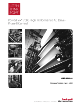
Configuration Example
This example illustrates how to setup a speed reference to follow a 0…10V analog
input signal and null out a small amount of offset from the A/D converter on the
analog input.
• Parameter 803 [Anlg ln1 Offset] = -0.0144V
• Parameter 802 [Anlg ln1 Scale] = 0.1 per 1V
• Parameter 804 [Al 1 Filt Gain] = 1
• Parameter 805 [Anlg ln1 Filt BW] = 0
• Parameter 10 [Speed Ref 1] is linked to parameter 800 [Anlg ln1 Data]
With a desired parameter 801 [Anlg In1 Value] of 0V, the drive was reading
0.0144V. To null out analog input 1, parameter 803 [Anlg In1 Offset] was set to -
0.0144V.
Parameter 10 [Speed Ref 1] is a per unit parameter, meaning that a value of 1
equates to base motor RPM. Therefore, to scale parameter 800 [Anlg In1 Data]
to give us a value from 0 to 1 for a 0…10V signal, parameter 802 [Anlg In1 Scale]
was set to 0.1 per 1V.
Parameter 805 [Anlg In1 Filt BW] was set to 0 so that no filtering took place on
analog input 1.
A/D
14bit
803
804
805
800
X
802
801
Anlg In1 Offset
Anlg In1 Scale
Anlg In1 Value
Anlg In1 Data
AI 1 Filt Gain
Anlg In1 Filt BW
TB1-01
TB1-02
+
-
Lead Lag
(kn * s)+ wn
s + wn
+
+
821 00
A
nalog I/O Units
(AI1 Current)

16 Rockwell Automation Publication PFLEX-RM003E-EN-E - January 2011
Chapter 1 Detailed Drive Operation
Analog Input Loss Detection
Signal loss detection can be enabled for each analog input. Parameters 1093, 1094
and 1095 [Anlg InxLossCnfg] control whether signal loss detection is enabled
for each input and defines what action the drive will take when loss of any analog
input signal occurs. One of the selections for reaction to signal loss is a drive fault,
which will stop the drive. All other choices make it possible for the input signal to
return to a usable level while the drive is still running.
If the input is in current mode, 4 mA is the normal minimum usable input value.
Any value below 3.2 mA will be interpreted by the drive as a signal loss, and a
value of 3.8 mA will be required on the input in order for the signal loss condition
to end.
If the input is in unipolar voltage mode, 2V is the normal minimum usable input
value. Any value below 1.6V will be interpreted by the drive as a signal loss, and a
value of 1.9V will be required on the input in order for the signal loss condition to
end. No signal loss detection is possible while an input is in bipolar voltage mode.
The signal loss condition will never occur even if signal loss detection is enabled.
Value Action on Signal Loss
0 Disabled (default)
1Fault
2 Hold Input - (continue to use last frequency command
3 Set Input Lo - use parameter 30 [Min Spd Ref Lim] as frequency command
4 Set Input Hi – use parameter 31 [Max Spd Ref Lim] as frequency command
5 Goto Preset1 – use parameter 14 [Preset Speed 1] as frequency command
6 Hold OutFreq - maintain last output frequency
4 mA
3.8 mA
3.2 mA
Signal Loss
Condition
End Signal Loss
Condition
2V
1.9V
1.6V
Signal Loss
Condition
End Signal Loss
Condition

Rockwell Automation Publication PFLEX-RM003E-EN-E - January 2011 17
Detailed Drive Operation Chapter 1
Analog Outputs
Analog Output Specifications
There are two analog outputs, differential, configurable for +/-10V or 0…20 mA.
The D/A (digital to analog) converter is 11 bits plus the sign bit.
Analog Output Configuration
Parameters 831 and 838 [Anlg Outx Sel] are use to specify the signal used on
Analog Outputs 1 and 2, respectively. These parameters can be programmed to
the following selections:
*Additionally, the analog output can be user configured for some other value by
setting [Anlg Outx Sel] to 0 “User Select” and linking either parameter 832 or
839 [Anlg Outx DInt] to a DInt (double integer) parameter or linking parameter
833 or 840 [Anlg Outx Real] to a floating point (real) parameter.
Parameter 834 or 841 [Anlg Outx Offset] is added to [Anlg Outx Real] or [Anlg
Outx DInt] before the scaling and limiting blocks.
The result of [Anlg Outx Offset] plus [Anlg Outx Real] or [Anlg Outx DInt] is
limited by 10 times the value of parameter 835 or 842 [Anlg Outx Scale]. Then
that limited value is divided by the value of [Anlg Outx Scale].
Parameter 836 or 843 [Anlg Outx Zero] is added after the scaling and limiting of
the analog output value. [Anlg Outx Zero] can be used to null out any offset from
the D/A converter.
Parameter 837 or 844 [Anlg Outx Value] displays the voltage or current value for
the analog output.
Bit Selection Corresponding
Parameter
Bit Selection Corresponding
Parameter
0 “User Select” (*see below) 15 “Motor TrqRef” 303 [Motor Torque Ref]
1 “Output Freq” 310 [Output Freq] 16 “MtrTrqCurRef” 305 [Mtr Trq Curr Ref]
2 “Sel Spd Ref” 40 [Selected Spd Ref] 17 “Speed Ref” 301 [Motor Speed Ref]
3 “Output Curr” 308 [Output Current] 18 “Speed Fdbk” 71 [Filtered SpdFdbk]
4 “Trq Cur (Iq)” 499 [Trq Cur Fdbk (Iq)] 19 “Torque Est” 471 [Estimated Torque]
5 “% Motor Flux” 309 [% Motor Flux] 20 “Scl Spd Fdbk” 72 [Scaled Spd Fdbk]
6 “Output Power” 311 [Output Power] 21 “RampedSpdRef” 43 [Ramped Spd Ref]
7 “Output Volts” 307 [Output Voltage] 22 “Spd Reg Out” 101 [SpdReg Integ Out]
8 “DC Bus Volts” 306 [DC Bus Voltage] 23 “MOP Level” 1090 [MOP Level Real]
9 “PI Reference” 181 [PI Reference] 24 “Trend 1 DInt” 572 [Trend Out1 DInt]
10 “PI Feedback” 182 [PI Feedback] 25 “Trend 1 Real” 573 [Trend Out1 Real]
11 “PI Error” 183 [PI Error] 26 “Trend 2 DInt” 576 [Trend Out2 DInt]
12 “PI Output” 180 [PI Output] 27 “Trend 2 Real” 577 [Trend Out2 Real]

18 Rockwell Automation Publication PFLEX-RM003E-EN-E - January 2011
Chapter 1 Detailed Drive Operation
Example Configuration 1:
This configuration sends the motor torque current reference value to a 0…10V
analog output signal.
• Parameter 831 [Anlg Out1 Sel] = 15 “Motor TrqRef ”
• Parameter 835 [Anlg Out1 Scale] = 0.1 per Volt
Motor torque is a per unit value where a value of 1 corresponds to 100% motor
torque. Therefore, parameter 831 [Anlg Out1 Scale] is set to 0.1 per 1V so that
when [Motor Torque Ref ] = 1 p.u., the analog output = 1 / 0.1 = 10V.
Example Configuration 2:
This configuration sends parameter 763 [Position Actual] out to a 0…10V analog
output signal.
• Parameter 831 [Anlg Out1 Sel] = 0 “User Select”
• Parameter 832 [Anlg Out1 DInt] is linked to parameter 763 [Position
Actual]
• Parameter 835 [Anlg Out1 Scale] is set to 214748364.7 per Volt
Parameter 763 [Position Actual] is an integer parameter with a range from
-2147483648 to +2147483647. Parameter 832 [Anlg Out1 DInt] is used
because parameter 763 [Position Actual] is an integer parameter.
Parameter 835 [Anlg Out1 Scale] is set to 214748364.7 per Volt so the analog
output will provide -10V when the position is -2147483647 and will +10V when
the position is +2147483647.
Auto/Manual
The Auto/Manual function on the LCD HIM is not functional on the
PowerFlex 700S drive with Phase II control.
Limit
10 [x]
X
1
[x]
833
834
835
836
D/A
12bit
837
Anlg Out1 DInt
A
nlg Out1 Real
Anlg Out1 Scale
Anlg Out1 Zero
Anlg Out1 Value
TB1-09
TB1-10
+
-
832
Anlg Out1 Offset
+
+
+
+
821 16
Analog I/O Units
(AO1 Current)
Selector
Anlg Out1 Sel 831
Dflt = 18

Rockwell Automation Publication PFLEX-RM003E-EN-E - January 2011 19
Detailed Drive Operation Chapter 1
Autotune
Auto-tuning is a procedure that involves running a group of tests on the motor/
drive combination. Some tests are checking the drive hardware while others
configure the drive parameters to maximize the performance of the attached
motor.
The auto-tuning procedure can be done using the Start-Up menu on the HIM.
Autotune - Start-Up Menu
The Start-Up menu prompts the user for information and yes/no responses as
required. The “Motor Control,” “Motor Data,” “Feedback Configuration,”
“Power Circuit Test,” “Direction Test,” “Motor Tests,” and “Inertia Measure”
submenus of the Start-Up menu are all related to the autotuning of the drive/
motor combination and are covered in this section.
Motor Control
The Motor Control submenu asks you to select the motor control operating
mode which sets the parameter 485 [Motor Ctrl Mode]. Choices are “FOC,”
“FOC 2,” “Pmag Motor,” “V/Hz” and “Test.”
• “FOC” selects field oriented control. This should be the selection for AC
squirrel cage induction motors.
• “FOC 2” selects field oriented control and is only used for a specific type of
AC induction motor with motor thermal feedback.
• For Phase II control V2.003 or later, “V/Hz” selects volts per hertz control.
• “Pmag Motor” selects control for permanent magnet motors.
• “Test” puts the drive in a test mode to perform the direction test. “Test” is
automatically selected during the direction test portion of the Start-Up
routine, and does not need to be set manually by the user.
Next, the motor control submenu asks you to select whether you have no
dynamic braking, an internal resistor for dynamic braking, or an external resistor
for dynamic braking. When no dynamic braking is selected, the bus regulator is
turned on (see Bus Regulation/Braking
on page 22 of this manual for more
details).
Motor Data
This submenu asks you to enter whether the motor power is in units of kW or
Hp. Then you are prompted to enter the motor nameplate data. Accurate motor
nameplate data is important for tuning the drive to the connected motor.

20 Rockwell Automation Publication PFLEX-RM003E-EN-E - January 2011
Chapter 1 Detailed Drive Operation
Feedback Configuration
The Feedback Configuration submenu asks you to select the feedback device
type. Possible selections are “Encoder 0,” “Encoder 1,” “Aux Speed,” “Motor Sim,”
or “Option Card.” Encoder 0 and Encoder 1 are for the encoders on the I/O
board. When “Encoder 0” or “Encoder 1” are selected, you must also enter the
encoder PPR. “Motor Sim” is to simulate a motor when there is no motor
connected to the drive. “Option Card” can be chosen when either the Resolver or
Hi-Resolution Encoder option cards are installed.
Power Circuit Test
This submenu allows you to perform a diagnostic check to check the output
section of the drive power circuit for shorts or open circuits.
Direction Test
The direction test checks the actual direction relative to the commanded
direction, and checks for proper encoder feedback. The test prompts you to
answer if the motor direction is correct. When it is not, you can either power
down and swap two of the motor leads, or change the drive’s logic to change the
motor direction. Then the test is performed again. The test then checks if the
feedback is positive. When it is not, you can either power down and swap two of
the encoder signals, or you can change the drive’s logic to change the sign of the
feedback. Then the test is performed again.
Motor Tests
This submenu performs the tests to measure the motor characteristics. These tests
can be performed with the motor coupled or uncoupled to the load, but be aware
that the motor will rotate during some of the tests.
/