Page is loading ...

Workrite Ergonomics | 800.959.9675 www.workriteergo.com 1 of 4
ABC
ID
A
B
C
1
1
6
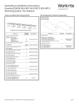
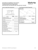
Large CPU Holder
Required, Sold Separately:
• Line of Sight Workcenter
• Central Processing Unit (CPU)
Included
Track Stop
#12 × ⅝ Phillips Head Screws
PART NAME QTY
B
A
Assembly & Installation Instructions:
Large CPU Holder
VE-CPUST
Remove Track Stop (B) from the CPU Holder (A)
Remove CPU Holder
from Track Face Plate
1

2 of 4 Workrite Ergonomics | 800.959.9675 www.workriteergo.com
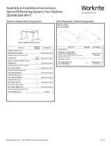
<¾"
DO NOT DRILL DEEPER THAN ¾”
See Positioning Guidelines on page 4.
Position and tape the Track Template (included in the box) on the underside of the worksurface, exactly where you
would like the CPU Holder to be installed.
Use a ⅛” drill bit to drill pilot holes at the four drill
locations in the template. You may wish to mark your
drill bit so you do not drill any more than ¾” deep
and damage your worksurface.
Place bracket on top of CPU with straps
around CPU
Firmly secure CPU by tightening the strap
Add slack to strap and align buckles to snap closed.
Attach the Track at the six “Preferred Locations” using six
#12 × ⅝” Phillips Head Screws (C). If you use an electric
screwdriver, be sure it is on the lowest torque setting to
avoid stripping the holes in the top.
2
3 4
View from below
Worksurface
Snap Buckle
Strap
View from above
Worksurface

3 of 4 Workrite Ergonomics | 800.959.9675 www.workriteergo.com
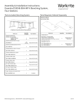
Å Back Front Æ
Pre-Installed Track Stop
Preferred Attachment Alternate Alternate
Preferred Attachment
Do not use Do not use
Do not use
Preferred Attachment
Preferred AttachmentPreferred Attachment
Preferred Attachment
Alternate
Note: Use Preferred Attachment locations if possible. If there are obstacles that
prevent attaching at Preferred Locations, choose the closest Alternate location.
Alternate
Note: Make sure this template
is printed at 100% scale. Select
"None" in Page Scaling menu
in printer dialog box.
ø 3 mm × 15 mm deep Pilot Hole
B
With the CPU Track mounted under worksurface,
slide swivel plate into Track.
TRACK TEMPLATE (included in the box)
With the CPU held securely, snap the Track Stop
(B) into the front of the Track.
5
✓
Swivel Plate
Track Face Plate

4 of 4 Workrite Ergonomics | 800.959.9675 www.workriteergo.com
1500400 Rev A
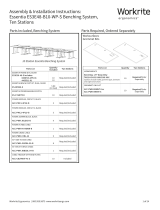
POSITIONING GUIDELINES
CPU Locations
Note: CPU placement will depend
on your over all room conguration,
Switch locations, Grommet Power
choices and in some instances,
cable lengths. Consider all wiring
objectives prior to installing CPU
Holders.
Single User Workstations can be
congured with the CPU on either
the left or right side of the Chassis.
Dual User Workstations can be
congured Left, Right, Inside or
Outside. Make sure you anticipate
all cabling needs and install the
CPU Holder(s) accordingly.
Single Le
Dual Le
Dual Outside
(preferred)
Single Right
Dual Right
Dual Inside
(avoid-may conflict with USB & switch)
A
B
B
A
B
B
A
B
BA
B
B
A
B
B
A
B
B
A
A
B
B
A
B
B
A
B
B
A
B
B
½ CPU
½ CPU
½ CPU
½ CPU
CPU Positioning
A = Front to back depth
B = Side to Side width
= Center Line
Single Le
Dual Le
Dual Outside
(preferred)
Single Right
Dual Right
Dual Inside
(avoid)
✓
/