Page is loading ...

Workrite Ergonomics | 800.959.9675 www.workriteergo.com 1 of 9
or
Assembly & Installation Instructions:
Line of Sight Electric, Dual User
LOS3-B-E21-XX-X
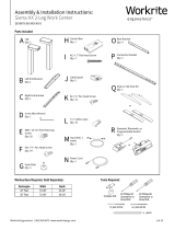
Parts Included
Required/Sold Separately Tools Required
½" Open ended wrench
9⁄16" Open ended wrench
4 mm Allen wrench Carpenters square
(T-square)
#2 Phillips screwdriver or
drill/driver with #2 tip
A Line of Sight Dual User
Electric Chassis
Qty: 1
9/16"
Hex
13/16"
25/64" 1"
0.375"
3/8"-16 Thread
C Right Top Bracket
Qty: 1
K⅜"Glides
Qty: 4
G #10 × ¾" Phillips Pan
Head Screws
Qty: 20
D 5⁄16"-18 Serrated
Flange Nut
Qty: 4
J ⅜-16x1"Flange
Head Cap Screws
Qty: 4
B Left Top Bracket
Qty: 1
H Left Foot
Qty: 1
I Right Foot
Qty: 1
E Dual User
Worksurface
Qty: 1 F Dual User
Monitor Bay Lid
Qty: 2
Q Quick Release
Monitor Adapter Kit
Qty: 2
R
Wire Loom, 1" × 2'
Qty: 2
M 3⁄16" P-Loops
Qty: 8
N#8×⅝"PhillipsPan
Head Screws
Qty: 8
L #5 × ¾ " Phillips Pan
Head Screws
Qty: 4
P Cable Ties
Qty: 10
O Cable Clips
Qty: 6

2 of 9 Workrite Ergonomics | 800.959.9675 www.workriteergo.com
ELECTRICAL RATINGS:
Monitor Li System Electrical Rating:
100/240 VAC, 50/60 Hz, 1.6 A
Power Track Electrical Ratings (Optional):
Models LOS3-PTXXXXX-XX-CXXXX
120/240 VAC, 20 A: E86969
120/208 VAC, 15 A: LR55351
120/240 VAC, 20 A: 117236
Power Bar Electrical Rating (Optional):
Models LOS3-MM024-4-XX
120 VAC, 60 Hz, 15 A : LR55351
SAVE THESE INSTRUCTIONS
WARNING: Maximumequipmentloadingoftableassemblyinadditionto
speciedtopisasfollows:
■ Maximumtopload:120lb(54.4kg)
■ Maximummonitorliftload(each):40lb(18.2kg)
Loadingshouldbeevenlydistributedovertablesurfaces.
FLAMMABILITY: AllworksurfacesusedmustmeetUL962ammabilityrequirements
■ FlameSpreadRatingmaximum200
■ SmokeDevelopedIndexmaximum450
IMPORTANT SAFETY INSTRUCTIONS:
When using an electrical furnishing, basic precautions should always be followed,
including the following:
ReadallinstructionsbeforeusingthisLineofSightEducationandTrainingWorkCenter.
DANGER: To reduce the risk of electric shock, always unplug this Line of Sight Education and Training Work Center from the electrical outlet
beforecleaningorservicing.
WARNING: Toreducetheriskofburns,re,electricshock,orinjurytopersons:
1. Unplugfromoutletbeforeputtingonortakingoffparts.
2. Closesupervisionisnecessarywhenthisfurnishingisusedby,ornearchildren,invalids,ordisabledpersons.
3. Use this furnishing only for its intended use as described in these instructions, do not use attachments not recommended by
themanufacturer.
4. Never operate this furnishing if it has a damaged cord or plug, is not working properly, has been dropped or damaged, or
droppedintowater.Returnthefurnishingtoaservicecenterforexaminationandrepair.
5. Keepthecordawayfromheatedsurfaces.
6. Neveroperatethefurnishingwiththeairopeningsblocked.Keeptheairopeningsfreeoflint,hair,andthelike.
7. Neverdroporinsertanyobjectintoanyopening.
8. Donotuseoutdoors.
9. Todisconnect,removeplugfromoutlet.
10. Mountonlyapprovedworksurfacesandsecondarysurfaces(shelves)inaccordancewithinstructions.Failuretodosomay
causeinstability,collapse,orfailureofelectricalcomponents.
Polarized Plug Instructions (Only applicable to products having a polarized plug power cord):
Some products include a polarized plug—see Figure A (One A/C plug blade wider than the other)—to reduce the risk of
electricalshock.Apolarizedplugonlytsapolarizedpoweroutletoneway.Ifthepolarizedplugdoesnottproperlyintothe
electricaloutletturnthepowerplugovertoseeifitthentsproperlyandfullyintotheoutlet.Iftheplugdoesstilldoesnott
theoutlet,contactacertiedelectriciantoinstallthecorrectmatchingpolarizedelectricaloutlet.
Caution: Never modify the power cord plug in any way
Double-Insulated Products Instructions:
Someproductsaredouble-insulated.Nomeansofgroundingisrequiredorprovidedonadouble-insulatedproduct;norisa
meansforgroundingtobeaddedtotheproduct.ThepluginadoubleinsulatedsystemisshowninFigure A.Double-insulated
productsareindicatedwithmarkingsof“double-insulated”orthe“doubleboxsymbol” orboth.
Grounding Instructions (For grounded electric products only):
Products with grounded power cords are for use on a nominal 120 V circuit and has a grounded plug as shown in Figure B
MakesuretheproductisconnectedtoanelectricaloutlethavingthesamecongurationastheplugshowninFigure C.
Caution: Never modify, remove, or use adapters that eliminate the ground connections from the grounded power cord
A/C Power:
ProductssoldinNorthAmericaandotherregionsare120VA/Casmarkedonthepowersupply/controlboxofthefurnishing
andaretobeusedonanormal120VA/Ccircuit.Alwaysfollowtheinstructionsaboveforpowerconnectionusinggroundedor
doubleinsulatedpowercordsassupplied.
• Only use power cord(s) supplied with your electric product
• Never modify, alter, use an adapter, or change the electrical system of this product in any way.
Warning: Doing so may cause risk of electrical shock or re
Illustration Disclaimer—Power Plug and Receptacle Images:
In some cases, the images in this instruction may not match the power cord supplied with your electrical furnishing based on your region.
Plug type, blade size, and shape may change.
Grounding Pin
Figure B
Grounded Outlet
Figure C
Polarized Plug
Figure A

Workrite Ergonomics | 800.959.9675 www.workriteergo.com 3 of 9
1.2
1.1
1.1
Rear Panel
Front Panel
Panel Lock
Protective Tape
2.1
Remove the Front and Rear Panels from
the Chassis (A) by turning the Panel
Locks a quarter turn towards the center
of the panel (inward), then pivot the
panels forward to remove
Useofkeylockisoptional.Usekeys
provided to lock or unlock as required
Keep the protective tape around panels
and on frame until assembly is complete
toprotectnish
REMOVE FRONT AND REAR PANELS, SET POWER CORD ASIDE
1.1
1.2
1
Attach the Left Top Bracket (B) and Right Top Bracket
(C) to Chassis (A) with the four 5⁄16"-18Locknuts(D).
Threaded studs on the brackets insert through holes in
the Chassis and are held in place with the Locknuts
ATTACH TOP BRACKETS
2.1
2
A
A
C
B
D
D 5⁄16"-18 Serrated Flange Nut
Hardware at actual size

4 of 9 Workrite Ergonomics | 800.959.9675 www.workriteergo.com
ATTACH FEET AND GLIDES
MOUNT CHASSIS ASSEMBLY TO WORKSURFACE & MONITOR BAY LIDS
3
4
With Worksurface correctly positioned on the Chassis
Assembly, attach Worksurface to Chassis Assembly with
eight#10×¾"PhillipsHeadScrews(G),threescrews
per Top Bracket (B & C) and two in the Center Support
Attach Monitor Bay Lids to both Monitor Lid Hinges with
twelve#10×¾"PhillipsHeadScrews(G)
Note: Therewillbeapproximately.15"ofclearance
between the Monitor Bay Lids and the Worksurface when
properly installed
3.1
4.1
3.2
4.2
3.2
3.2
3.1
3.1
J ⅜-16×1"FlangeHeadCapScrew
Hardware at actual size
Attach to Worksurface Attach to Monitor Bay Lid
4.2
4.2
4.1
4.1
Attach Left Foot (H) and Right Foot (I) to bottom of Chassis
usingfour⅜-16×1"FlangeHeadSocketCapScrews(J)
ScrewinthefourGlides(K)intothefeetapproximatelyhalfway.
You will level the Work Center once it is fully assembled
H
J
I
K
G
G
K
B
C
J
G #10 × ¾" Phillips
Pan Head Screws
Hardware at actual size

Workrite Ergonomics | 800.959.9675 www.workriteergo.com 5 of 9
Power Supply
Battery Backup
ROUTE & ATTACH SWITCHES
5
Detach the two Switch taped to side of Chassis and
route the Control Switch around the frame and to the
front of the Worksurface as shown
Attach Switch at the pre-drilled holes at the front of the
worksurface with #5 × ¾" Phillips Pan Head Screws (L)
AttachsixP-Loops(M)toDesktopatpre-drilled
locations, making sure to wrap Cable Loop around
cablepriortoattachingusingthe#8×⅝"PhillipsPan
Head Screws (N)
Note: Fasten P-Loops from the Switch (front) to
back, keeping cable tight against the bottom of the
worksurface.TakeupslackwithCableTies(P)tokeep
wires from the Monitor Lift travel area
5.1
5.2
5.3
L #5 × ¾" Phillips Pan Head
Screws
Hardware at actual size
N#8×⅝"PhillipsPanHead
Screws
Hardware at actual size
5.1
5.1
Behind
frame
Behind
frame
Switch taped
here
Switch taped
here
Power Cord
taped here
Switch
Underside of Switch
PLUG IN WORK CENTER
6
Detach the Power Cord taped to back of Chassis and
temporarily route the cord from the Power Supply and plug
intopower.
Note the location of your Optional Battery Backup:
Caution: Do not install batteries until all electronics
are installed and you are connected to a “constant on”
power circuit or you will drain the batteries!
By installing two 9 V batteries (not included) in this
location you will have enough power for two to three
emergencyclosuresifpowergoesout.Waituntilyour
entirecongurationispoweredinStep 16toinstall.
6.1
6.2
6.1
6.2
L
L
5.2
5.2
5.2
5.3
Fasten front to
back, picking
up slack
1
2
3
M
N

Workrite Ergonomics | 800.959.9675 www.workriteergo.com 6 of 9
X
X
.25"
≤ .25"
INSTALL POWER DISTRIBUTION OPTIONS FOR YOUR CONFIGURATION
WiththeWorkCenterbuilt,youwillnowneedtoaddyourpoweroptionsforyourspecicconguration.Followtheinstructionsthatcame
withthePowerSystemOptionstocompleteyourconguration.
If you did not purchase the Power Track or Power Bar, skip to Step 8.
INSTALL QUICK RELEASE MONITOR ADAPTER(S)
Note:Youwillneedtomountthemonitorsinordertodeterminethecorrectinstallationheight.
Remove the monitor from the factory mount, if necessary, and retain the screws that came with
themonitor.
AttachQuickReleaseMonitorAdapter(Q)tothebackofyourVESAcompatibleMonitor.
Note:Usethescrews(andspacers)thatbestfastenyourmonitortotheAdapter.Thesemaybe
the original monitor screws, or one of the three lengths included with the Quick Release Adapter
hardwarekit.Manymonitors(Dell)havearecessedmountwherethespacerswillberequired.
Note: You can install the monitor directly on the Monitor Lift VESA plate and NOT use the Quick
ReleaseAdapterifsecurityisanissue.Thismakesitmoredifcult(butnotimpossible)toremove
themonitorsquickly.
Ifyouarebuildingadualmonitorconguration,usetheQuickReleaseAdapterfromtheDual
MonitorAdapterKitforthesecondmonitor.
SET MONITOR HEIGHT
Measure and note the distance from the top of the Quick
ReleaseAdaptertothetopofthemonitor("X").
Remove the Monitor Lift VESA Plate by removing the two
atheadscrewswiththe4mmAllenwrench.
Repositionsothatwheninstalled,themonitorisatleast.25"
belowtheMonitorLifttop.
X+.25"=installationheight.
Reattachusingthetwoathead
screwswiththe4mmAllenwrench.
8.1
9.1
Monitor topQuick Release top
Back view
Quick Release from Dual
Monitor Adapter Kit for dual
monitor congurations
8.2
7
8
9
8.1
9.1
8.2
9.2
9.3
9.4
9.5
Q
X
X
.25"
≤ .25"
X
X
.25"
≤ .25"
X
X
.25"
≤ .25"
9.2
9.5
9.4
9.3
9.3
Monitor Lift
Monitor Lift
VESA Mount
Plate
Monitor
Side view
Installed
Remove
Replace
Q
Q

7 of 9 Workrite Ergonomics | 800.959.9675 www.workriteergo.com
INSTALL MONITORS
INSTALL OPTIONAL ACCESSORIES FOR YOUR CONFIGURATION
INSTALL TECHNOLOGY FOR YOUR CONFIGURATION
MANAGE CABLING
10
11
12
13
10.1
O
R
P
Slide the Quick Release Monitor Adapter onto the VESA mounts
IMPORTANT:Conrmthatthemonitorisinstalledlowerthanthe
Monitor Lift and that the Monitor Lift raises the Monitor Lid and
not the monitor!
Withthemonitorsandpowercomponentsinstalled,youwillnowneedtoaddyouroptionalaccessorieslikeWorksurfaceGrommets,
RemoteControlsandCPUHolders.FollowtheinstructionswiththeOptionalAccessoriestocompletethisstep.
WithallLineofSightcomponentsinstalled,youwillnowneedtoinstallallthetechnologycomponentstocompleteyoursystem.Install
all computers, peripherals like keyboards and mice, and network cabling to complete your installation according to the manufacturers
specicationsandyourspecicapplication.
With monitors and technology installed, you'll want to start
consideringallthecablingrequirements.
Note: It is critical that no wires interfere with the travel of
theMonitorLift.UseCableClips(O)forsinglewires(mouse
& keyboard) and Cable Ties (P) for multiple wires to fasten
all cabling securely out of the way of all moving Monitor Lift
components.
Use the Wire Loom (S) to manage all user cables routing from
thekeyboardtraytotheCPU.Thismayincludekeyboard,
mouse,monitoranddatacables.
Keyboard tray cable
access
Inside Chassis
To CPU
Monitor Lift
Single Monitor, Dual User Conguration

Workrite Ergonomics | 800.959.9675 www.workriteergo.com 8 of 9
REMOVE PROTECTIVE TAPE & REPLACE FRONT AND REAR PANELS
14
14.1
14.2
Remove the protective tape on the Panels and Chassis
Reattachyourfrontandrearpanels.Younowhaveacomplete
WorkCenter.FinishbuildingallWorkCentersbeforeproceeding
tonalroomassembly.
ASSEMBLE FINAL ROOM CONFIGURATION & CONNECT TO POWER SOURCE
INSTALL BATTERIES IN POWER SUPPLY FOR BATTERY BACKUP (OPTIONAL)
15
16
WithallindividualWorkCentersBuiltandelectricalinstalled,arrangeWorkCentersaccordingtoyournal
roomconguration.YouwillneedatleasttwopeopletomoveaWorkCenter.
AdjusttheGlides(K)onthebottomoftheFeettoassureeachWorkCenterislevelandstableinitsnallocation.
Note:Itiscriticalthatyoufollowallwarningsandcautionswhenyougettonalassembly.Consulttheinstructionsthatcamewith
yourelectricalcomponentsandfollowallcautionsandwarningscarefully!Congurationswithsharedpowermustconformtocode
andincludeuseofGangingBracketsforSidetoSidecongurationsorBacktoBackFillerPlatesforBacktoBackcongurations.
FinalassemblywillincludetestingofelectricalcomponentsandfunctioningofallMonitorLifts.
With all technology installed, cables routed and fastened and the system connected to constant power, add two 9 V batteries to the
PowerSupplyforBatteryBackup.Intheeventofapoweroutage,thebatterybackupwillallow2–3emergencyclosurestostowthe
technology.SeeStep 6.2forbackupbatteryinstallationlocation.
Important: The Power Supply MUST be plugged into a “constant on” power circuit or the batteries will discharge! Replace batteries
onceayear.
Remove
Front & Rear Panels Chassis
Remove
14.1
14.1

9 of 9 Workrite Ergonomics | 800.959.9675 www.workriteergo.com
1500553 Rev B
Laminate Worksurfaces:
Foreverydaycleaning,wipethesurfacewithadampclothorsponge.Useaspraycleaningagentsparinglyifnecessary(suggestedspray
cleaningagentsareindicatedbelow).Donotpourwaterdirectlyontotheworksurface.Wipecompletelydrywithasoftragusingastraight
linemotion.
• Worksurfacesmayneedoccasionaldusting.Tokeepthesurfaceinidealcondition,useanon-oilyfurniturespray.
• Difcultstainssuchascoffeecanberemovedusingamildcleaningdetergentandasoftbristled(non-metallic)brush.Donotscrub
surfaceswithtoomuchforce,otherwisethesurfacecouldloseitsnish.
• Stubbornstainsthatresistanyoftheabovecleaningmethodsmayrequiretheuseofundilutedhouseholdbleach.Applyaverysmall
amountofbleach(approximately¼-capful)tothestainandletstandnolongerthantwominutes.Rinsethoroughlywithwarmwaterand
wipedry.WARNING:Prolongedexposureofthelaminatesurfacewithbleachwillcausediscoloration.
• Ensuretoalwaysrinselaminatesurfacesaftercleaning.Evenasmallamountofcleaningresiduecanresultinpermanentdiscolorations.
• Recommended Laminate Worksurface cleaning agents:
•Non-abrasivespraycleaningagents:Dawn,Fantastik,Windex,Lysol
• Furniture spray: Pledge
•Stainremovers:Lestoil,Clorox
Painted steel parts:
• Clean surfaces regularly with damp cloth
• Ifnecessary,useaspraycleaningagent(e.g.Fantastik)sparingly.Wipecompletelydrywithasoftragusingastraightlinemotion.
• Lightly brush both vertical and horizontal surfaces to prevent dust build-up
Polished chrome feet:
• ThefeetcanbepolishedwhentheybecomedullwithAluminumpolish(e.g.FlitzorMothersMagPolish)withspecialattentiontokeep
polishfrompaintedsurfaces.Followmanufacturersinstructionsforbestresults.
CLEANING INSTRUCTIONS
✓
/