Page is loading ...

PowerFlex 7000 Medium Voltage AC Drive Air-Cooled
(’A’ Frame)—ForGe Control
Bulletin Number 7000A
User Manual
Original Instructions

Important User Information
Read this document and the documents listed in the additional resources section about installation, configuration, and
operation of this equipment before you install, configure, operate, or maintain this product. Users are required to
familiarize themselves with installation and wiring instructions in addition to requirements of all applicable codes, laws,
and standards.
Activities including installation, adjustments, putting into service, use, assembly, disassembly, and maintenance are
required to be carried out by suitably trained personnel in accordance with applicable code of practice.
If this equipment is used in a manner not specified by the manufacturer, the protection provided by the equipment may
be impaired.
In no event will Rockwell Automation, Inc. be responsible or liable for indirect or consequential damages resulting from
the use or application of this equipment.
The examples and diagrams in this manual are included solely for illustrative purposes. Because of the many variables and
requirements associated with any particular installation, Rockwell Automation, Inc. cannot assume responsibility or
liability for actual use based on the examples and diagrams.
No patent liability is assumed by Rockwell Automation, Inc. with respect to use of information, circuits, equipment, or
software described in this manual.
Reproduction of the contents of this manual, in whole or in part, without written permission of Rockwell Automation,
Inc., is prohibited
Throughout this manual, when necessary, we use notes to make you aware of safety considerations.
Labels may also be on or inside the equipment to provide specific precautions.
WARNING: Identifies information about practices or circumstances that can cause an explosion in a hazardous
environment, which may lead to personal injury or death, property damage, or economic loss.
ATTENTION: Identifies information about practices or circumstances that can lead to personal injury or death, property
damage, or economic loss. Attentions help you identify a hazard, avoid a hazard, and recognize the consequence.
IMPORTANT Identifies information that is critical for successful application and understanding of the product.
SHOCK HAZARD: Labels may be on or inside the equipment, for example, a drive or motor, to alert people that dangerous
voltage may be present.
BURN HAZARD: Labels may be on or inside the equipment, for example, a drive or motor, to alert people that surfaces may
reach dangerous temperatures.
ARC FLASH HAZARD: Labels may be on or inside the equipment, for example, a motor control center, to alert people to
potential Arc Flash. Arc Flash will cause severe injury or death. Wear proper Personal Protective Equipment (PPE). Follow ALL
Regulatory requirements for safe work practices and for Personal Protective Equipment (PPE).

Rockwell Automation Publication 7000A-UM200G-EN-P - February 2020 3
Table of Contents
Preface
Summary of Changes . . . . . . . . . . . . . . . . . . . . . . . . . . . . . . . . . . . . . . . . . . . 9
Who Should Use This Manual . . . . . . . . . . . . . . . . . . . . . . . . . . . . . . . . . . 9
What Is Not in This Manual . . . . . . . . . . . . . . . . . . . . . . . . . . . . . . . . . . . . 9
General Precautions . . . . . . . . . . . . . . . . . . . . . . . . . . . . . . . . . . . . . . . . . . . . 9
Additional Resources . . . . . . . . . . . . . . . . . . . . . . . . . . . . . . . . . . . . . . . . . . 10
Chapter 1
Overview of Drive Introduction. . . . . . . . . . . . . . . . . . . . . . . . . . . . . . . . . . . . . . . . . . . . . . . . . . 11
Topology . . . . . . . . . . . . . . . . . . . . . . . . . . . . . . . . . . . . . . . . . . . . . . . . . . . . . 11
Rectifier Designs . . . . . . . . . . . . . . . . . . . . . . . . . . . . . . . . . . . . . . . . . . . . . . 12
Configurations . . . . . . . . . . . . . . . . . . . . . . . . . . . . . . . . . . . . . . . . . . . . 12
Motor Compatibility . . . . . . . . . . . . . . . . . . . . . . . . . . . . . . . . . . . . . . . . . . 14
Simplified Electrical Drawings. . . . . . . . . . . . . . . . . . . . . . . . . . . . . . . . . . 15
2400V . . . . . . . . . . . . . . . . . . . . . . . . . . . . . . . . . . . . . . . . . . . . . . . . . . . . 15
3300/4160V . . . . . . . . . . . . . . . . . . . . . . . . . . . . . . . . . . . . . . . . . . . . . . 16
6600V . . . . . . . . . . . . . . . . . . . . . . . . . . . . . . . . . . . . . . . . . . . . . . . . . . . . 17
Safe Torque Off . . . . . . . . . . . . . . . . . . . . . . . . . . . . . . . . . . . . . . . . . . . 18
Operator Interface . . . . . . . . . . . . . . . . . . . . . . . . . . . . . . . . . . . . . . . . . . . . 19
Basic Configurations. . . . . . . . . . . . . . . . . . . . . . . . . . . . . . . . . . . . . . . 19
Chapter 2
Drive Installation Safety and Codes . . . . . . . . . . . . . . . . . . . . . . . . . . . . . . . . . . . . . . . . . . . . . . 21
Drive Storage . . . . . . . . . . . . . . . . . . . . . . . . . . . . . . . . . . . . . . . . . . . . . . . . . 21
Siting of the Drive. . . . . . . . . . . . . . . . . . . . . . . . . . . . . . . . . . . . . . . . . . . . . 21
Site Considerations . . . . . . . . . . . . . . . . . . . . . . . . . . . . . . . . . . . . . . . . 21
Generator Note . . . . . . . . . . . . . . . . . . . . . . . . . . . . . . . . . . . . . . . . . . . 22
Installation . . . . . . . . . . . . . . . . . . . . . . . . . . . . . . . . . . . . . . . . . . . . . . . . . . . 23
Shock Indication Labels. . . . . . . . . . . . . . . . . . . . . . . . . . . . . . . . . . . . 23
Installation of Exhaust Air Hood . . . . . . . . . . . . . . . . . . . . . . . . . . . 24
Installation of Redundant Fan Assembly. . . . . . . . . . . . . . . . . . . . . 27
Installation of Integral Transformer Cooling Fan. . . . . . . . . . . . . 29
Neutral Resistor Assembly . . . . . . . . . . . . . . . . . . . . . . . . . . . . . . . . . 30
Installation of Neutral Resistor Assembly (Direct-to-Drive). . . 31
Cabinet Layout and Dimensional Drawings of Drive . . . . . . . . . . . . . 32
Drive Layout. . . . . . . . . . . . . . . . . . . . . . . . . . . . . . . . . . . . . . . . . . . . . . . . . . 34
IEC Component and Device Designations . . . . . . . . . . . . . . . . . . . . . . 37
Selection of Power Wiring . . . . . . . . . . . . . . . . . . . . . . . . . . . . . . . . . . . . . 37
General Notes. . . . . . . . . . . . . . . . . . . . . . . . . . . . . . . . . . . . . . . . . . . . . 37
Cable Insulation. . . . . . . . . . . . . . . . . . . . . . . . . . . . . . . . . . . . . . . . . . . 37
Power Cabling Access . . . . . . . . . . . . . . . . . . . . . . . . . . . . . . . . . . . . . . . . . 40
Access the Customer Power Cable-terminations . . . . . . . . . . . . . 40
Power Connections . . . . . . . . . . . . . . . . . . . . . . . . . . . . . . . . . . . . . . . . . . . 41
Line/Motor Terminations . . . . . . . . . . . . . . . . . . . . . . . . . . . . . . . . . 41
Installation Requirements for Power Cabling . . . . . . . . . . . . . . . . 41

4 Rockwell Automation Publication 7000A-UM200G-EN-P - February 2020
Table of Contents
Power and Control Wiring. . . . . . . . . . . . . . . . . . . . . . . . . . . . . . . . . . . . . 46
Control Cables. . . . . . . . . . . . . . . . . . . . . . . . . . . . . . . . . . . . . . . . . . . . 46
Grounding Practices. . . . . . . . . . . . . . . . . . . . . . . . . . . . . . . . . . . . . . . . . . . 46
Drive Signal and Safety Grounds. . . . . . . . . . . . . . . . . . . . . . . . . . . . 48
For Customers and Power Integrators . . . . . . . . . . . . . . . . . . . . . . . 48
Identification of Types of Electrical Supplies - Grounded and
Ungrounded Systems . . . . . . . . . . . . . . . . . . . . . . . . . . . . . . . . . . . . . . 49
Ground Bus. . . . . . . . . . . . . . . . . . . . . . . . . . . . . . . . . . . . . . . . . . . . . . . 49
Interlocking . . . . . . . . . . . . . . . . . . . . . . . . . . . . . . . . . . . . . . . . . . . . . . . . . . 49
Chapter 3
Power Component Definition and
Maintenance
Cabling Cabinet Components. . . . . . . . . . . . . . . . . . . . . . . . . . . . . . . . . . 51
Hall Effect Sensor Replacements. . . . . . . . . . . . . . . . . . . . . . . . . . . . . . . . 55
Current Transformer Replacement . . . . . . . . . . . . . . . . . . . . . . . . . . . . . 56
Converter Cabinet Components . . . . . . . . . . . . . . . . . . . . . . . . . . . . . . . 58
Converter Cabinet . . . . . . . . . . . . . . . . . . . . . . . . . . . . . . . . . . . . . . . . . . . . 61
Voltage-sensing Assembly . . . . . . . . . . . . . . . . . . . . . . . . . . . . . . . . . . . . . . 61
Replacing the Voltage-sensing Circuit Board Assembly . . . . . . . . . . . 62
Surge Arresters. . . . . . . . . . . . . . . . . . . . . . . . . . . . . . . . . . . . . . . . . . . . . . . . 63
Description . . . . . . . . . . . . . . . . . . . . . . . . . . . . . . . . . . . . . . . . . . . . . . . 63
Operation . . . . . . . . . . . . . . . . . . . . . . . . . . . . . . . . . . . . . . . . . . . . . . . . 64
Surge Arrester Replacement . . . . . . . . . . . . . . . . . . . . . . . . . . . . . . . . 64
Field Test and Care . . . . . . . . . . . . . . . . . . . . . . . . . . . . . . . . . . . . . . . . 65
PowerCage Module Overview . . . . . . . . . . . . . . . . . . . . . . . . . . . . . . . . . . 66
Resistance Checks . . . . . . . . . . . . . . . . . . . . . . . . . . . . . . . . . . . . . . . . . . . . . 67
SGCT and Snubber Circuit . . . . . . . . . . . . . . . . . . . . . . . . . . . . . . . . 68
SGCT Anode-to-Cathode Sharing Resistance . . . . . . . . . . . . . . . 73
Snubber Resistance . . . . . . . . . . . . . . . . . . . . . . . . . . . . . . . . . . . . . . . . 74
Snubber Capacitance . . . . . . . . . . . . . . . . . . . . . . . . . . . . . . . . . . . . . . 75
Replacing the SGCT. . . . . . . . . . . . . . . . . . . . . . . . . . . . . . . . . . . . . . . 77
Replacing Snubber and Sharing Resistor . . . . . . . . . . . . . . . . . . . . . 80
Snubber Capacitor Replacement. . . . . . . . . . . . . . . . . . . . . . . . . . . . . . . . 82
Sharing Resistor Replacement . . . . . . . . . . . . . . . . . . . . . . . . . . . . . . 83
Maintain Uniform Clamping Pressure . . . . . . . . . . . . . . . . . . . . . . . . . . 83
Adjusting the Clamping Pressure . . . . . . . . . . . . . . . . . . . . . . . . . . . 84
Temperature Sensing . . . . . . . . . . . . . . . . . . . . . . . . . . . . . . . . . . . . . . . . . . 85
Replacing the Thermal Sensor . . . . . . . . . . . . . . . . . . . . . . . . . . . . . . 85
Heatsink Replacement. . . . . . . . . . . . . . . . . . . . . . . . . . . . . . . . . . . . . . . . . 87
PowerCage Gasket . . . . . . . . . . . . . . . . . . . . . . . . . . . . . . . . . . . . . . . . . . . . 88
Replacement of PowerCage Gaskets. . . . . . . . . . . . . . . . . . . . . . . . . 89
Removal of Old Gasket Material . . . . . . . . . . . . . . . . . . . . . . . . . . . . 89
PowerCage Module Removal. . . . . . . . . . . . . . . . . . . . . . . . . . . . . . . . . . . 90
Self-powered SGCT Power Supply - SPS . . . . . . . . . . . . . . . . . . . . . . . . 92
Board Calibration . . . . . . . . . . . . . . . . . . . . . . . . . . . . . . . . . . . . . . . . . 92
Test Points. . . . . . . . . . . . . . . . . . . . . . . . . . . . . . . . . . . . . . . . . . . . . . . . 92
Equipment for Testing. . . . . . . . . . . . . . . . . . . . . . . . . . . . . . . . . . . . . 94
Fiber-optic Cabling. . . . . . . . . . . . . . . . . . . . . . . . . . . . . . . . . . . . . . . . . . . . 95

Rockwell Automation Publication 7000A-UM200G-EN-P - February 2020 5
Table of Contents
Air Pressure Sensor . . . . . . . . . . . . . . . . . . . . . . . . . . . . . . . . . . . . . . . . . . . . 96
Air Pressure Sensor Replacement . . . . . . . . . . . . . . . . . . . . . . . . . . . 96
D.C. Link / Fan / Control Components . . . . . . . . . . . . . . . . . . . . . . . . 97
Output Grounding Network Replacement . . . . . . . . . . . . . . . . . . 99
Ground Filter Component Replacement . . . . . . . . . . . . . . . . . . . 100
Filter Capacitors . . . . . . . . . . . . . . . . . . . . . . . . . . . . . . . . . . . . . . . . . . . . . 101
Replacing the Filter Capacitors . . . . . . . . . . . . . . . . . . . . . . . . . . . . 103
Testing the Filter Capacitors . . . . . . . . . . . . . . . . . . . . . . . . . . . . . . 104
DC Link Reactor and CMC Replacement. . . . . . . . . . . . . . . . . . . . . . 107
Fan Replacement. . . . . . . . . . . . . . . . . . . . . . . . . . . . . . . . . . . . . . . . . . . . . 109
DC Link Section . . . . . . . . . . . . . . . . . . . . . . . . . . . . . . . . . . . . . . . . . 109
Fan Installation . . . . . . . . . . . . . . . . . . . . . . . . . . . . . . . . . . . . . . . . . . 110
Top of Integral Isolation Transformer Section . . . . . . . . . . . . . . 111
Top of Integral Line Reactor and Input Starter Section . . . . . . 112
Impeller Maintenance . . . . . . . . . . . . . . . . . . . . . . . . . . . . . . . . . . . . . . . . 112
Isolation Transformer Cooling Fan . . . . . . . . . . . . . . . . . . . . . . . . 112
Inlet Ring Removal and Replacement . . . . . . . . . . . . . . . . . . . . . . . . . . 112
DC Link / Fan Section. . . . . . . . . . . . . . . . . . . . . . . . . . . . . . . . . . . . 113
Top of Integral Isolation Transformer Section . . . . . . . . . . . . . . 113
Replacement of Air Filters . . . . . . . . . . . . . . . . . . . . . . . . . . . . . . . . . . . . 114
Fan Power Transformer. . . . . . . . . . . . . . . . . . . . . . . . . . . . . . . . . . . . . . . 117
Chapter 4
Control Component Definition
and Maintenance
Control Power Components . . . . . . . . . . . . . . . . . . . . . . . . . . . . . . . . . . 119
Ride-through. . . . . . . . . . . . . . . . . . . . . . . . . . . . . . . . . . . . . . . . . . . . . 119
AC/DC Power Supply. . . . . . . . . . . . . . . . . . . . . . . . . . . . . . . . . . . . . . . . 123
Description . . . . . . . . . . . . . . . . . . . . . . . . . . . . . . . . . . . . . . . . . . . . . . 123
Location . . . . . . . . . . . . . . . . . . . . . . . . . . . . . . . . . . . . . . . . . . . . . . . . . 124
Terminal / Connections Descriptions. . . . . . . . . . . . . . . . . . . . . . 126
Output Calibration. . . . . . . . . . . . . . . . . . . . . . . . . . . . . . . . . . . . . . . 127
Single Power Supply Replacement . . . . . . . . . . . . . . . . . . . . . . . . . 128
Dual Power Supply Replacement . . . . . . . . . . . . . . . . . . . . . . . . . . 129
Diode Replacement. . . . . . . . . . . . . . . . . . . . . . . . . . . . . . . . . . . . . . . 131
UPS Option . . . . . . . . . . . . . . . . . . . . . . . . . . . . . . . . . . . . . . . . . . . . . . . . . 132
Replacing the UPS. . . . . . . . . . . . . . . . . . . . . . . . . . . . . . . . . . . . . . . . 133
Low Voltage Control Section . . . . . . . . . . . . . . . . . . . . . . . . . . . . . . . . . 135
DC/DC Power Supply . . . . . . . . . . . . . . . . . . . . . . . . . . . . . . . . . . . . . . . 135
Description . . . . . . . . . . . . . . . . . . . . . . . . . . . . . . . . . . . . . . . . . . . . . . 135
Terminal/Connections Descriptions. . . . . . . . . . . . . . . . . . . . . . . 136
Replacement Procedure for DC/DC Power Supply. . . . . . . . . . 137
Printed Circuit Board Replacement. . . . . . . . . . . . . . . . . . . . . . . . . . . . 138
Drive Processor Module . . . . . . . . . . . . . . . . . . . . . . . . . . . . . . . . . . . . . . 139
Drive Processor Module Replacement . . . . . . . . . . . . . . . . . . . . . . 141
Analog Control Board . . . . . . . . . . . . . . . . . . . . . . . . . . . . . . . . . . . . . . . . 143
Interface Module (IFM). . . . . . . . . . . . . . . . . . . . . . . . . . . . . . . . . . . 147
Analog Inputs and Outputs . . . . . . . . . . . . . . . . . . . . . . . . . . . . . . . 147
Current Loop Transmitter . . . . . . . . . . . . . . . . . . . . . . . . . . . . . . . . 148

6 Rockwell Automation Publication 7000A-UM200G-EN-P - February 2020
Table of Contents
Isolated Process Receiver . . . . . . . . . . . . . . . . . . . . . . . . . . . . . . . . . . 149
Non-Isolated Process Outputs . . . . . . . . . . . . . . . . . . . . . . . . . . . . . 150
Auxiliary +24V Power Supply . . . . . . . . . . . . . . . . . . . . . . . . . . . . . 150
Replacing the Analog Control Board . . . . . . . . . . . . . . . . . . . . . . . 151
Encoder Feedback Board. . . . . . . . . . . . . . . . . . . . . . . . . . . . . . . . . . . . . . 151
Encoder Options . . . . . . . . . . . . . . . . . . . . . . . . . . . . . . . . . . . . . . . . . 151
Quadrature Encoder Operation. . . . . . . . . . . . . . . . . . . . . . . . . . . . 156
Positional Encoder Operations . . . . . . . . . . . . . . . . . . . . . . . . . . . . 156
Positional Encoder Guidelines . . . . . . . . . . . . . . . . . . . . . . . . . . . . . 157
External Input/output Boards. . . . . . . . . . . . . . . . . . . . . . . . . . . . . . . . . 158
External Input/output Board Replacement . . . . . . . . . . . . . . . . . 159
Optical Interface Boards . . . . . . . . . . . . . . . . . . . . . . . . . . . . . . . . . . . . . . 160
Optical Interface Board Replacement . . . . . . . . . . . . . . . . . . . . . . 162
Appendix A
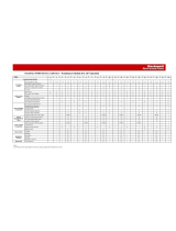
Catalog Number Explanation PowerFlex 7000 Drive Selection Explanation . . . . . . . . . . . . . . . . . . . 167
Service Duty Rating, Continuous Current Rating and
Altitude Rating Code . . . . . . . . . . . . . . . . . . . . . . . . . . . . . . . . . . . . . 167
Appendix B
Preventative Maintenance
Schedule
Preventative Maintenance Checklist . . . . . . . . . . . . . . . . . . . . . . . . . . . 169
Operational Maintenance. . . . . . . . . . . . . . . . . . . . . . . . . . . . . . . . . . . . . 169
Annual Maintenance . . . . . . . . . . . . . . . . . . . . . . . . . . . . . . . . . . . . . . . . . 169
Initial Information Gathering . . . . . . . . . . . . . . . . . . . . . . . . . . . . . 170
Physical Checks . . . . . . . . . . . . . . . . . . . . . . . . . . . . . . . . . . . . . . . . . . 170
Control Power Checks (No Medium Voltage) . . . . . . . . . . . . . . 171
Final Power Checks before Restarting . . . . . . . . . . . . . . . . . . . . . . 172
Additional Tasks during Preventive Maintenance . . . . . . . . . . . 172
Final Reporting. . . . . . . . . . . . . . . . . . . . . . . . . . . . . . . . . . . . . . . . . . . 173
Time Estimations . . . . . . . . . . . . . . . . . . . . . . . . . . . . . . . . . . . . . . . . 173
Tool / Parts / Information Requirements. . . . . . . . . . . . . . . . . . . 174
Maintenance Schedule. . . . . . . . . . . . . . . . . . . . . . . . . . . . . . . . . . . . . . . . 175
General Notes . . . . . . . . . . . . . . . . . . . . . . . . . . . . . . . . . . . . . . . . . . . . . . . 178
Maintenance of Medium Voltage Equipment . . . . . . . . . . . . . . . 178
Periodic Inspection . . . . . . . . . . . . . . . . . . . . . . . . . . . . . . . . . . . . . . . 178
Contamination. . . . . . . . . . . . . . . . . . . . . . . . . . . . . . . . . . . . . . . . . . . 179
High-voltage Testing . . . . . . . . . . . . . . . . . . . . . . . . . . . . . . . . . . . . . 179
Maintenance after a Fault Condition. . . . . . . . . . . . . . . . . . . . . . . 179
Part-specific Notes . . . . . . . . . . . . . . . . . . . . . . . . . . . . . . . . . . . . . . . . . . . 180
Cooling-fans . . . . . . . . . . . . . . . . . . . . . . . . . . . . . . . . . . . . . . . . . . . . . 180
Operating Mechanisms . . . . . . . . . . . . . . . . . . . . . . . . . . . . . . . . . . . 180
Contacts. . . . . . . . . . . . . . . . . . . . . . . . . . . . . . . . . . . . . . . . . . . . . . . . . 180
Vacuum Contactors . . . . . . . . . . . . . . . . . . . . . . . . . . . . . . . . . . . . . . 180
Power Cable and Control Wire Terminals. . . . . . . . . . . . . . . . . . 181
Coils . . . . . . . . . . . . . . . . . . . . . . . . . . . . . . . . . . . . . . . . . . . . . . . . . . . . 181
Batteries . . . . . . . . . . . . . . . . . . . . . . . . . . . . . . . . . . . . . . . . . . . . . . . . . 181

Rockwell Automation Publication 7000A-UM200G-EN-P - February 2020 7
Table of Contents
Pilot Lights . . . . . . . . . . . . . . . . . . . . . . . . . . . . . . . . . . . . . . . . . . . . . . 181
Solid-state Devices. . . . . . . . . . . . . . . . . . . . . . . . . . . . . . . . . . . . . . . . 181
Locking and Interlocking Devices. . . . . . . . . . . . . . . . . . . . . . . . . . 182
Appendix C
Torque Requirements Torque Requirements for Threaded Fasteners . . . . . . . . . . . . . . . . . . 183
Appendix D
Insulation Resistance Testing Drive Insulation Resistance Testing. . . . . . . . . . . . . . . . . . . . . . . . . . . . 185
Insulation Resistance Testing Procedures. . . . . . . . . . . . . . . . . . . . . . . 186
Appendix E
Line and Load Cable Sizes Maximum Line Cable Sizes . . . . . . . . . . . . . . . . . . . . . . . . . . . . . . . . . . . 191
Maximum Load Cable Sizes . . . . . . . . . . . . . . . . . . . . . . . . . . . . . . . . . . . 192
Appendix F
Environmental Considerations Air Quality Requirements. . . . . . . . . . . . . . . . . . . . . . . . . . . . . . . . . . . . . 193
Hazardous Materials. . . . . . . . . . . . . . . . . . . . . . . . . . . . . . . . . . . . . . . . . . 194
Capacitor Dielectric Fluid. . . . . . . . . . . . . . . . . . . . . . . . . . . . . . . . . 194
Printed Circuit Boards . . . . . . . . . . . . . . . . . . . . . . . . . . . . . . . . . . . . 194
Lithium Batteries. . . . . . . . . . . . . . . . . . . . . . . . . . . . . . . . . . . . . . . . . 194
Chromate Plating . . . . . . . . . . . . . . . . . . . . . . . . . . . . . . . . . . . . . . . . 195
In Case Of Fire. . . . . . . . . . . . . . . . . . . . . . . . . . . . . . . . . . . . . . . . . . . 195
Disposal . . . . . . . . . . . . . . . . . . . . . . . . . . . . . . . . . . . . . . . . . . . . . . . . . 195
Appendix G
Pre -Commissioning Start-up Commissioning Services . . . . . . . . . . . . . . . . . . . . . . . . . . . . . . 197
Pre- Commissioning the Drive. . . . . . . . . . . . . . . . . . . . . . . . . . . . . 197
Appendix H
Specifications Drive Specifications . . . . . . . . . . . . . . . . . . . . . . . . . . . . . . . . . . . . . . . . . . 199
Index
. . . . . . . . . . . . . . . . . . . . . . . . . . . . . . . . . . . . . . . . . . . . . . . . . . . . . . . . 203

8 Rockwell Automation Publication 7000A-UM200G-EN-P - February 2020
Table of Contents
Notes:

Rockwell Automation Publication 7000A-UM200G-EN-P - February 2020 9
Preface
This document provides procedural information for managing the PowerFlex®
7000 medium voltage ‘A’ frame drives.
Summary of Changes
This manual contains new and updated information as indicated in the
following table.
Who Should Use This Manual
This manual is intended for use by personnel familiar with medium voltage
and solid-state variable speed drive equipment. The manual contains material
that enables regular operation and maintenance of the drive system.
What Is Not in This Manual
This manual provides information specific to the maintenance of the
PowerFlex® 7000 ‘A’ frame drive. The manual excludes topics such as:
• Dimensional and electrical drawings that are generated for each
customer order.
• Spare part lists compiled for each customer order.
• Human Machine Interface (HMI) operation and configuration.
Rockwell Automation provides the site- and installation-specific electrical and
design information for each drive during the order process cycle. If they are not
available on site with the drive, contact Rockwell Automation®.
General Precautions
Topic Page
Added warning for motor filter capacitors and indicative fault codes 103
Changed input frequency to ±5% 199
ATTENTION: This drive contains ESD (electrostatic discharge) sensitive parts
and assemblies. Static control precautions are required when this assembly is
installed, tested, serviced, or repaired. Component damage can result if ESD
control procedures are not followed. If you are not familiar with static control
procedures, reference Allen-Bradley publication 8000-4.5.2
, “Guarding
Against Electrostatic Damage” or any other applicable ESD protection
handbook.
ATTENTION: An incorrectly applied or installed drive can result in
component damage or a reduction in product life. Wiring or application
errors, such as, an undersized motor, incorrect or inadequate AC supply, or
excessive ambient temperatures can result in malfunction of the system.

10 Rockwell Automation Publication 7000A-UM200G-EN-P - February 2020
Preface
Additional Resources
These publications contain additional information concerning “A” Frame
drives and related products from Rockwell Automation.
You can view or download publications at
http://www.rockwellautomation.com/global/literature-library/overview.page
.
To request paper copies of technical documentation, contact your local
Allen-Bradley distributor or Rockwell Automation sales representative.
ATTENTION: Only personnel familiar with the PowerFlex 7000 Adjustable
Speed Drive (ASD) and associated machinery can plan or implement the
installation, start up, and subsequent maintenance of the system. Failure to
comply can result in personal injury and/or equipment damage.
Publication Description
7000-PP002
PowerFlex 7000 Air-Cooled Drives Product Profile
7000-TD002 PowerFlex 7000 Medium Voltage AC Drive (firmware revision 11or later) -
ForGe Control
7000-UM201 PowerFlex 7000 HMI Offering with Enhanced Functionality
7000-QS002
HMI Interface Board Software Updater and Firmware Download Procedure
7000-IN010 Handling, Inspection, and Storage of Medium Voltage Line Filter Capacitors
Industrial Automation Wiring and
Grounding Guidelines, publication
1770-4.1
Provides general guidelines for installing a Rockwell Automation industrial
system.
Product Certifications website,
rok.auto/certifications
.
Provides declarations of conformity, certificates, and other certification
details.

Rockwell Automation Publication 7000A-UM200G-EN-P - February 2020 11
Chapter 1
Overview of Drive
Introduction
The PowerFlex® 7000 drive is a general-purpose, standalone, medium voltage
drive. The drive controls speed, torque, direction, and the start and stops of
standard asynchronous or synchronous AC motors. The PowerFlex 7000
works on numerous standard and specialty applications such as fans, pumps,
compressors, mixers, conveyors, kilns, fan-pumps, and test stands. The
PowerFlex 7000 is used in industries such as petrochemical, cement, mining
and metals, forest products, power generation, and water/waste water.
The PowerFlex 7000 drive meets most common standards from the National
Electrical Code (NEC), International Electrotechnical Commission (IEC),
National Electrical Manufacturers Association (NEMA), Underwriters
Laboratories (UL), and Canadian Standards Association (CSA). The
PowerFlex 7000 is available with most common supply voltages at medium
voltage, from 2400...6600V.
Topology
The PowerFlex 7000 drive uses a pulse width modulated (PWM) – current
source inverter (CSI) topology. This topology offers a simple, cost-effective
power structure that is easy to apply to a wide voltage and power range. The
power semiconductor switches used are easy-to-series for any medium voltage
level. Semiconductor fuses are not required for the power structure due to the
current limiting DC link inductor.
With 6500V PIV rated power semiconductor devices, the number of inverter
components is kept to a minimum. For example, only six inverter switching-
devices are required at 2400V, 12 at 3300...4160V, and 18 at 6600V.
The PowerFlex 7000 drive provides inherent regenerative-braking for
applications where the load is overhauling the motor. Or where high inertia
loads are slowed down quickly. Symmetrical gate-commutated thyristors
(SGCTs) are used for machine converter switches and line converter switches.
The PowerFlex 7000 drive provides a selectable option for enhanced torque
control capabilities and increased dynamic control performance. This high-
performance torque control (HPTC) feature delivers 100% torque at zero
speed and provides torque control through zero speed with smooth direction
transition.

12 Rockwell Automation Publication 7000A-UM200G-EN-P - February 2020
Chapter 1 Overview of Drive
Rectifier Designs
Configurations
The PowerFlex 7000 drive offers three rectifier configurations for "A" Frame
drives:
• Direct-to-Drive™ (Active Front End [AFE] rectifier with integral line
reactor and Common Mode Choke)
• AFE rectifier with separate isolation transformer
• AFE rectifier with integral isolation transformer
Direct-to-Drive
Direct-to-Drive technology does not require an isolation transformer or
multiple rectifier bridges. Instead of multiple uncontrolled rectifiers, an AFE
rectifier bridge is supplied. The rectifier semiconductors that are used are
symmetrical gate commutated thyristors (SGCTs). Unlike the diodes that are
used in VSI (voltage source inverter) rectifier bridges, SGCTs are turned on
and off by a gating signal. A pulse-width modulation (PWM) gating-algorithm
controls the firing of the rectifier devices, similar to the control philosophy of
the inverter. The gating algorithm uses a specific 42 pulse switching-pattern
(Figure 1
) called selective harmonic elimination (SHE) to mitigate the 5th,
7th, and 11th harmonic orders
Figure 1 - Typical PWM Switching-pattern, Line Voltage Waveform
An integral line reactor and capacitor addresses the high harmonic orders
(13th and above). The integral line reactor and capacitor also provide
sinusoidal voltage and current waveforms back to the distribution system. The
capacitor delivers excellent line-side harmonic and power factor performance
to meet IEEE 519-1992 requirements and other global harmonic standards.
All while providing a simple, robust power structure that maximizes uptime by
minimizing the number of discrete components and the number of
interconnections required.
A common mode choke (CMC) mitigates the common mode voltage that is
seen at the motor terminals. Standard (non-inverter duty rated) motors and
motor cables can be used. This technology is ideal for motor retrofit
applications.
An integral starter is offered as an option.

Rockwell Automation Publication 7000A-UM200G-EN-P - February 2020 13
Overview of Drive Chapter 1
Figure 2 - 3300/4160V Direct-to-Drive (Transformerless AFE Rectifier)
AFE Rectifier with Separate Isolation Transformer
For applications when the line voltage is higher than the motor voltage, a
transformer is required for voltage matching. In this case, providing an AFE
rectifier with a separate isolation transformer is ideal (indoor and outdoor
transformer versions are offered). The isolation transformer provides the input
impedance (which replaces the integral line reactor) and addresses the
common mode voltage (which replaces the CMC that is in the Direct-to-Drive
rectifier configuration). However, the AFE rectifier, its operation, and
advantages are the same as the Direct-to-Drive™ configuration.
Figure 3 - 3300/4160 AFE Rectifier with Separate Isolation Transformer
AFE Rectifier with Integral Isolation Transformer
For applications that require a higher power rating than available with Direct-
to-Drive, providing an AFE rectifier with an integral isolation transformer is
ideal (indoor and outdoor transformer versions are offered). The isolation
transformer provides the input impedance (which replaces the integral line
reactor) and addresses the common mode voltage (which replaces the CMC in
the Direct-to-Drive rectifier configuration). However, the AFE rectifier, its
operation, and advantages are the same as the Direct-to-Drive configuration.
SGCTs
L+
M+
SGCTs
U(T1)
V(T2)
W(T3)
L-
M-
LR
Line Converter
Common Mode Choke Machine Converter
SGCTs
L+
M+
SGCTs
U(T1)
V (T2)
W(T3)
L-
M-
2U (X1)
2V (X2)
2W (X3)
1U
1V
1W
Line Converter
DC Link Machine Converter
Remote ISTX

14 Rockwell Automation Publication 7000A-UM200G-EN-P - February 2020
Chapter 1 Overview of Drive
Figure 4 - 3300/4160 AFE Rectifier with Integral Isolation Transformer
Motor Compatibility
The PowerFlex 7000 achieves near sinusoidal current and voltage waveforms to
the motor, with no significant additional heating or insulation stress. The
motor that is connected to the VFD is typically 3 °C (5.4 °F) higher compared
to across-the-line operation. Voltage waveform has dv/dt of less than 50V/µs.
Reflected wave and dv/dt issues that are often associated with VSI drives do
not exist with the PowerFlex 7000. Typical motor waveforms are shown in
Figure 5
. These waveforms use a selective harmonic elimination (SHE) pattern
in the inverter to eliminate major order harmonics. And with a small output
capacitor (integral to the drive) to eliminate harmonics at higher speeds.
Standard motors are compatible without derating, even on retrofit
applications.
Motor cable distance is unlimited. This technology can of control motors up to
15 km (9.3 miles) away from the drive.
Figure 5 - Motor Wave Forms at Full Load, Full Speed
2U (X1)
2V (X2)
2W (X3)
1
U
1
V
1
W
SGCTs
L+
M+
SGCTs
U(T1)
V(T2)
W (T3)
L-
M-
Line Converter
DC Link
Machine Converter
Internal ISTX
300.00
200.00
100.00
0.00
-
100.00
-
200.00
-
300.00
10.00K
7.50K
5.00K
2.50K
0.00K
-2.50K
-5.00K
-7.50K
-
10.00K
100.00
110.00
120.00 130.00
TIME
(
ms
)
140.00
150.0
0
Arms
Vrms
Motor Current
Motor Voltage

Rockwell Automation Publication 7000A-UM200G-EN-P - February 2020 15
Overview of Drive Chapter 1
Simplified Electrical
Drawings
2400V
Figure 6 - 2400V - Direct-to-Drive (Transformerless AFE Rectifier)
Figure 7 - 2400 Volt – AFE Rectifier with Separate Isolation Transformer
Figure 8 - 2400 Volt – AFE Rectifier with Integral Isolation Transformer
SGCTs
L+
M+
SGCTs
U(T1)
V(T2)
W(T3)
L-
M-
LR
L1
L2
L3
Line Converter
Common Mode Choke Machine Converter
Optional Input Starter
SGCTs
L+
M+
SGCTs
U(T1)
V (T2)
W (T3)
L-
M-
2U (X1)
2V (X2)
2W (X3)
1U
1V
1W
Line Converter
DC Link
Machine Converter
Remote ISTX
2U (X1)
2V (X2)
2W (X3)
1U
1V
1W
SGCTs
L+
M+
SGCTs
U(T1)
V (T2)
W (T3)
L-
M-
Line Converter
DC Link
Machine Converter
Integral ISTX

16 Rockwell Automation Publication 7000A-UM200G-EN-P - February 2020
Chapter 1 Overview of Drive
3300/4160V
Figure 9 - Direct-to-Drive (Transformerless AFE Rectifier)
Figure 10 - AFE Rectifier with Separate Isolation Transformer
Figure 11 - AFE Rectifier with Integral Isolation Transformer
SGCTs
SGCTs
U(T1)
V(T2)
W(T3)
L-
M-
LR
L1
L2
L3
Line Converter
Common Mode Choke Machine Converter
Optional Input Starter
SGCTs
L+
M+
SGCTs
U (T1)
V (T2)
W(T3)
L-
M-
2U (X1)
2V (X2)
2W (X3)
1U
1V
1W
Line Converter
%DC Link
Machine Converter
Remote ISTX
2U (X1)
2V (X2)
2W (X3)
1
U
1
V
1
W
SGCTs
L+
M+
SGCTs
U(T1)
V(T2)
W (T3)
L-
M-
Line Converter
DC Link
Machine Converter
Integral ISTX

Rockwell Automation Publication 7000A-UM200G-EN-P - February 2020 17
Overview of Drive Chapter 1
6600V
Figure 12 - Direct-to-Drive (Transformerless AFE Rectifier)
Figure 13 - AFE Rectifier with Separate Isolation Transformer
Figure 14 - AFE Rectifier with Integral Isolation Transformer
SGCTs
LINE CONVERTER
L+
M+
SGCTs
MACHINE CONVERTER
U(T1)
V(T2)
W(T3)
L-
M-
LR
L1
L2
L3
COMMON MODE CHOKE
OPTIONAL INPUT STARTER
SGCTs
LINE CONVERTER DC LINK
L+
M+
SGCTs
MACHINE CONVERTER
U(T1)
V (T2)
W (T3)
L-
M-
2U (X1)
2V (X2)
2W (X3)
1U
1V
1
W
ISTXISTX
REMOTE
SGCTs
LINE CONVERTER DC LINK
L+
M+
SGCTs
MACHINE CONVERTER
U (T1)
V (T2)
W(T3)
L-
M-
2U (X1)
2V (X2)
2W (X3)
1U
1V
1W
INTEGRAL
ISTX

18 Rockwell Automation Publication 7000A-UM200G-EN-P - February 2020
Chapter 1 Overview of Drive
Safe Torque Off
Safe Torque Off is a functional safety feature that is integrated into the
PowerFlex 7000, available for Active Front End (AFE) and Direct-to-Drive
configurations. The drive can receive a safety input signal (for example, from
an optical sensor or a safety gate). Then remove rotational power from the
motor to allow the motor to coast to a stop. After the Safe Torque Off
command is initiated, the drive will declare it's in the safe state. The drive itself
remains powered and the safe state is reliably monitored to make sure that no
rotational torque can be delivered to the motor. The drive can return rotational
power to the motor after Safe Torque Off condition has been reset.
Figure 15 - Safe Torque Off
An internal safety relay provides for the safety input and reset circuits.
Safe Torque Off can be used in Active Front End (AFE) and Direct-to-Drive
rectifier drive configurations for A, B, and C frames. Safe Torque Off cannot be
used for parallel drives, N+1, N-1, synchronous transfer and 18 pulse drive
configurations.
This feature TÜV certified for use in safety applications up to and including
safety integrity level 3 (SIL3) and Category 3, Performance Level e (Cat 3,
PLe). More information on functional safety and SIL and PL ratings can be
found in the following standards:
• EN 61508
• EN 62061
• EN 61800-5-2
• EN 13849-1
See publication 7000-UM203
for more information that is related to the
functional safety option.
Speed
Motor Power
Stop Request
Stop Time
Coast
Time
Time

Rockwell Automation Publication 7000A-UM200G-EN-P - February 2020 19
Overview of Drive Chapter 1
Operator Interface
The HMI Interface Board is an HMI-enabling device for the PowerFlex 7000
drive. The HMI Interface Board accesses all necessary executable tools,
documentation, and reports required to commission, troubleshoot, and
maintain the drive.
By way of the HMI Interface Board, you can choose the style and size of the
desired Windows-based operator terminal to interact with the drive. For
example, PanelView™ CE terminal, laptop, or desktop computer). The HMI
Interface Board removes past issues with compatibility between the drive and
configuration tools, as all necessary tools are acquired from the drive.
The HMI Interface Board is well suited for applications that require remote
placement of the operator terminal and remote maintenance.
Figure 16 - Operator Interface
Basic Configurations
There are three basic configurations for the HMI:
•Remote mounted
• Locally mounted
•No HMI supplied

20 Rockwell Automation Publication 7000A-UM200G-EN-P - February 2020
Chapter 1 Overview of Drive
Remote-mounted HMI
The HMI is not mounted in the traditional location on the low voltage door of
the Variable Frequency Drive (VFD). A remote mounting plate, complete with
E-stop push button, and HMI is supplied loose for the customer to mount
wherever desired. The HMI connects to the VFD by way of a hardwired
Ethernet cable. There is no significant functional distance-limit, which is ideal
for non-PLC users wanting to control and monitor remotely. For example, at
the driven machine or control room. This usage is ideal for customers who have
control policies in place. These policies must control the access to medium
voltage equipment and the associated requirements of PPE when using the
operator interface at the VFD.
Locally Mounted HMI
Similar to the previously offered PanelView™ 550, the HMI is mounted on the
LV door of the VFD. There is also a service access port (RJ45 connector) on
the LV door.
No HMI Supplied
A service access port (RJ45 connector) is on the LV door of the VFD.
Customers use their own laptop as the HMI. All programs that are required to
use the laptop as the HMI are stored in the VFD. The laptop is connected to
the VFD by way of a hardwired Ethernet cable, when required. This
connection is ideal for unmanned sites, where a dedicated HMI is not
required.
See Publication 7000-UM201
for detailed instruction for the HMI.
See Publication 7000A-UM151
for detailed instruction for “A” Frame drives
that use the PanelView 550 HMI.
/