Page is loading ...

Installation Instructions
Original Instructions
PowerFlex 755 AC Drives Cabinet Blower Assembly
Frames 8…10
Remove Power from the Drive
1. Turn off and lock out all input power, including any and all external power
sources. For common DC input drives only, turn off input power and lock
the drive disconnect switch SW2 and circuit breaker SW5 (if used).
SK-R1-FAN4-F8
ATTENTION: To avoid an electric shock hazard, verify that the voltage on the
bus capacitors has discharged completely before servicing. Measure the DC bus
voltage at the –DC and +DC TESTPOINT sockets on the front of the power
module (see below for location).
Remove power before making or breaking cable connections. When you remove or
insert a cable connector with power applied, an electrical arc may occur. An
electrical arc can cause personal injury or property damage by:
• sending an erroneous signal to your system’s field devices, causing unintended
machine motion
• causing an explosion in a hazardous environment
Electrical arcing causes excessive wear to contacts on both the module and its
mating connector. Worn contacts may create electrical resistance.
ATTENTION: To avoid an electric shock hazard when servicing the drive, a
means for Lockout/Tagout of an external 120V uninterruptible power supply
and/or external 120/240V power source must be provided, or the circuit breaker
SW5 must be locked and tagged. Locking and tagging the common bus
precharge disconnect switch SW2 alone does not provide sufficient protection
when servicing the drive.

Rockwell Automation Publication 750-IN026B-EN-P - March 2019
2 PowerFlex 755 AC Drives Cabinet Blower Assembly
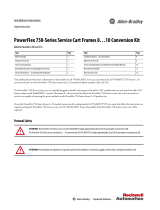
2. Wait 15 minutes and verify that there is no voltage at the drive’s input
power terminals.
3. Measure the DC bus voltage at the –DC and +DC TESTPOINT sockets
on the front of the power module.
Frame 9 Common DC Input Drive Shown
SW2
SW5
Frame 8 AC Input Drive Shown

Rockwell Automation Publication 750-IN026B-EN-P - March 2019
PowerFlex 755 AC Drives Cabinet Blower Assembly 3
Remove Blower Assembly
1. Remove power from the drive.
Follow the
Remove Power from the Drive procedure starting on page 1.
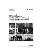
2. Remove the ten hexalobular screws that secure the blower assembly to the
drive cabinet.
3. Pull the blower assembly off the cabinet.
4.
Disconnect the power cable.
Clean Sealing Surface
1. Carefully remove any gasket material that may be stuck to the sealing
surface.
2. Clean the sealing surface with a 50% isopropyl alcohol / 50% water
mixture.
T25

4 PowerFlex 755 AC Drives Cabinet Blower Assembly
Publication 750-IN026B-EN-P – March 2019
Supersedes Publication 750-IN026A-EN-P March 2012 Copyright © 2019 Rockwell Automation, Inc. All rights reserved. Printed in USA.
Allen-Bradley, PowerFlex, Rockwell Automation, and Rockwell Software are trademarks of Rockwell Automation, Inc.
Trademarks not belonging to Rockwell Automation are property of their respective companies.
Rockwell Otomasyon Ticaret A.Ş., Kar Plaza İş Merkezi E Blok Kat:6 34752 İçerenköy, İstanbul, Tel: +90 (216) 5698400
Rockwell Automation maintains current product environmental information on its website at
http://www.rockwellautomation.com/rockwellautomation/about-us/sustainability-ethics/product-environmental-compliance.page.
Install Blower Assembly
1. Remove power from the drive.
Follow the
Remove Power from the Drive procedure starting on page 1.
2. Connect the power cable.
3. Align the blower assembly mounting holes.
4. Insert screws and tighten using an alternating pattern.
4.0 N•m (35 lb•in)
T25
Rockwell Automation Support
For technical support, visit http://www.rockwellautomation.com/support/overview.page.
/