Page is loading ...

Service Bulletin
Enwatch 24V DC Replacement Kit
Catalog Numbers
EK-44750C, EK-44750C-RK24V series B
Topic Page
Important User Information 2
Before You Begin 3
Parts List 3
Identify the Enwatch Board Issue 4
Identify the Power Supply 4
Exchange the Enwatch Boards and Power Supplies 5
Remove the Enwatch Board 5
Remove the Power Supply Mounting Base Plate 7
Install the New Power Supply Mounting Base Plate 8
Install the Enwatch Board 8

Rockwell Automation Publication GMSI10-SB001A-EN-P - May 2013
2 Enwatch 24V DC Replacement Kit
Important User Information
Solid-state equipment has operational characteristics differing from those of electromechanical equipment. Safety Guidelines for the Application, Installation and Maintenance of Solid
State Controls (publication
SGI-1.1 available from your local Rockwell Automation sales office or online at http://www.rockwellautomation.com/literature/) describes some important
differences between solid-state equipment and hard-wired electromechanical devices. Because of this difference, and also because of the wide variety of uses for solid-state equipment,
all persons responsible for applying this equipment must satisfy themselves that each intended application of this equipment is acceptable.
In no event will Rockwell Automation, Inc. be responsible or liable for indirect or consequential damages resulting from the use or application of this equipment.
The examples and diagrams in this manual are included solely for illustrative purposes. Because of the many variables and requirements associated with any particular installation,
Rockwell Automation, Inc. cannot assume responsibility or liability for actual use based on the examples and diagrams.
No patent liability is assumed by Rockwell Automation, Inc. with respect to use of information, circuits, equipment, or software described in this manual.
Reproduction of the contents of this manual, in whole or in part, without written permission of Rockwell Automation, Inc., is prohibited.
Throughout this manual, when necessary, we use notes to make you aware of safety considerations.
WARNING: Identifies information about practices or circumstances that can cause an explosion in a hazardous environment, which may lead to personal injury or
death, property damage, or economic loss.
ATTENTION: Identifies information about practices or circumstances that can lead to personal injury or death, property damage, or economic loss. Attentions help you
identify a hazard, avoid a hazard and recognize the consequences.
SHOCK HAZARD: Labels may be on or inside the equipment, for example, a drive or motor, to alert people that dangerous voltage may be present.
BURN HAZARD: Labels may be on or inside the equipment, for example, a drive or motor, to alert people that surfaces may reach dangerous temperatures.
IMPORTANT Identifies information that is critical for successful application and understanding of the product.

Rockwell Automation Publication GMSI10-SB001A-EN-P - May 2013
Enwatch 24V DC Replacement Kit 3
Before You Begin
Use these instructions to exchange an Issue F and earlier Enwatch® online
surveillance board that is powered by a 12V DC power supply with an Issue G
board that is powered by a 24V DC power supply.
The boards can be differentiated by the issue letter. All Issue F or earlier boards
are powered with a 12V DC power supply. All Issue G or later boards are
powered by 24V DC power supplies. All other functionality is the same. See
Identify the Enwatch Board Issue and Identify the Power Supply on page 4 for
more information.
Parts List
Enwatch 24V DC Replacement Kit, catalog number EK-44750C-RK24V
series B, contains the following:
• 24V DC Enwatch board (Issue G)
• Mounting base plate fitted with 24V DC power supply
Use the Enwatch replacement kit when it is not possible to ship the entire
Enwatch enclosure system to a Rockwell Automation repair center.
IMPORTANT
• These instructions apply only to Enwatch boards P/N EK-44750C. Enwatch CSANI P/N
EK-44750CSANI must be returned to a Rockwell Automation repair center for all
board replacements and repairs.
• All Enwatch boards (EK-44750C and EK-44750CSANI) built before July 2005 were
powered by a 12V DC power supply. All boards shipped after July 2005 operate using
a 24V DC power supply.
• It is important to use the correct power supply when exchanging Enwatch boards.
Using the incorrect power supply can cause damage to the Enwatch board.
• Always replace both the board and the power supply using the components
supplied in the kit, catalog number EK-44750C-RK24V series B.
Note: Repairs and retrofits should be made only by authorized Rockwell service
personnel.
IMPORTANT
The kit is designed to replace the EK-44750C Enwatch board. To avoid mismatching the
power supply and Enwatch board, you must replace the mounting base plate (with 24V
DC power supply) and board at the same time. Do not replace only the board.

Rockwell Automation Publication GMSI10-SB001A-EN-P - May 2013
4 Enwatch 24V DC Replacement Kit
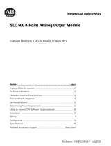
Identify the Enwatch Board Issue
Every Enwatch board is labeled with an issue letter. For Issue F and earlier boards,
the issue letter is on the lower-right corner of the board. For Issue G and later
boards, the issue letter is in the upper-left corner of the board. Also, when looking
at the power regulator, Issue F and earlier boards have a black heat sink in
comparison to the Issue G and later boards that have a silver rectangle marked
Traco Power.
Figure 1 - Board Identification
Identify the Power Supply
The 12V DC power supply has a blue label. The 24V DC power supply is smaller
and is labeled 24V.
Figure 2 - Power Supply Identification
IMPORTANT
The Enwatch boards must be powered by the correct voltage.
• Connect the 12V DC power supply to Issue F and earlier boards.
• Connect the 24V DC power supply to Issue G and later boards.
Issue F
Issue G
Issue Letter
Heat Sink
Traco Power
12V DC
24V DC
Blue Label
24V Label

Rockwell Automation Publication GMSI10-SB001A-EN-P - May 2013
Enwatch 24V DC Replacement Kit 5
Exchange the Enwatch Boards
and Power Supplies
Removal and replacement of the Enwatch board and mounting base plate should
be performed only at the request of Rockwell Automation Repair Center
personnel when it is not feasible to return the Enwatch system to a Repair Center.
Remove the Enwatch Board
Use these instructions and figures to remove the Enwatch board.
Figure 3 - Mains Power Input and Earth Ground Terminals
1. Remove power from the mains input wires.
2. Disconnect the mains power input and earth grounding wires, shown in
Figure 3.
ATTENTION:
• Only qualified electrical personnel familiar with the construction and operation of this
equipment, and who have been trained in the repair of this equipment and the hazards
involved should install, adjust, operate, or service and repair this equipment.
• Read and understand this document procedure in its entirety before proceeding. Failure
to observe this precaution could result in severe bodily injury or loss of life.
• Never attempt to service an Enwatch system while it is powered. Ensure that all power
to the Enwatch system has been disconnected by following proper local safety and
lockout procedures.
• If your system does not resemble the one described in these instructions immediately
contact Rockwell Automation Technical Support.
ATTENTION: Never attempt to service an Enwatch board while powered.
Ensure that all power to the entire Enwatch system has been disconnected and follow
the local safety and lockout procedures.
Earth Ground Terminal Strip
Mains Power Input and
Earth Ground Terminals

Rockwell Automation Publication GMSI10-SB001A-EN-P - May 2013
6 Enwatch 24V DC Replacement Kit
3. Disconnect the DC power supply cable from the Enwatch board (1).
4. Remove the Ethernet cable (2).
5. Remove the sensor Input Connector Blocks (3 and 4).
6. If there are trigger inputs, remove them (58).
7. Remove the six screws (914).
8. Carefully lift the board off of the standoffs to avoid static discharge or
other contact that might damage the board, and place it inside a static-free
package for proper storage.
Figure 4 - Jumper and Screw Locations
A - B
A - B A - B A - B A - B A - B A - B
A - B
A - B A - B A - B A - B A - B
A - B
A - B
TX
RX LK OB
+
_
1 - 2 - 3 - 4 - 5 - 6 - 7 - 8 9-10-11-12-13-14-15-16 1 - 2 - 3 - 4 - 5 - 6 - 7 - 8
9-10-11-12-13-14-15-16
33
22
1
33
22
1
33
22
1
33
22
1
A - B
# Description
1 DC power supply terminal
2 Ethernet terminal
3,4 Input connector blocks
58 Trigger inputs
914 Screws
1
2
43
5
6
9
7
8
10
11
12
13
14

Rockwell Automation Publication GMSI10-SB001A-EN-P - May 2013
Enwatch 24V DC Replacement Kit 7
Remove the Power Supply Mounting Base Plate
Use these instructions and figure to remove the power supply mounting base
plate.
Figure 5 - Wire and Screw Locations
1. Follow the steps in the Remove the Enwatch Board section to safely
remove the board.
2. If sensor grounding wires are connected to the grounding terminal strip,
disconnect them.
3. Remove the four mounting base-plate screws and washers (circled).
4. Lift the mounting base plate out of the Enwatch enclosure.
ATTENTION:
• Ensure that all power to the Enwatch system has been disconnected by following
proper local safety and lockout procedures.
• Only properly trained and certified professionals should complete these steps.
• If your system does not resemble the one described in these instructions
immediately contact Rockwell Automation Technical Support.
Grounding Terminal Strip

Allen-Bradley, Rockwell Software, Rockwell Automation, and Enwatch are trademarks of Rockwell Automation, Inc.
Trademarks not belonging to Rockwell Automation are property of their respective companies.
Publication GMSI10-SB001A-EN-P - May 2013
Supersedes Publication ICM-IN004A-EN-P - July 2009 Copyright © 2013 Rockwell Automation, Inc. All rights reserved. Printed in the U.S.A.
Rockwell Otomasyon Ticaret A.Ş., Kar Plaza İş Merkezi E Blok Kat:6 34752 İçerenköy, İstanbul, Tel: +90 (216) 5698400
Install the New Power Supply Mounting Base Plate
Use these instructions to install the new power supply mounting base plate.
1. Fit the new mounting base plate in position and replace the four mounting
base-plate screws and washers removed in
step 3 on page 7.
2. Reconnect the sensor grounding wires removed in
step 2 on page 7.
Install the Enwatch Board
1. Place the Enwatch board on the mounting base-plate standoffs and replace
the screws and washers removed in
step 7 on page 6.
2. Reconnect the Ethernet cables, and the sensor and trigger connector
removed in steps
4, 5, and 6 on page 6.
3. Reconnect the DC power supply cable to the Enwatch board removed in
step 3 on page 6.
4. To reconnect mains power to the Enwatch unit, follow these steps.
a. Ensure that the mains input cables are isolated at source from mains
power.
b. Reconnect the earth grounding wire that was removed in
step 2 on page 5.
c. Remove the yellow safety cover from the live (L) and neutral (N)
terminals.
d. Reconnect mains input wires that were removed in
step 2 on page 5,
paying attention to terminal markings live (L) and neutral (N).
e. Verify that all connections are safely made, then replace the yellow
safety cover.
f. Restore power at mains source.
g. Verify that the DC power input status indicator is green.
/