Page is loading ...

USER MANUAL
Firmware Version 1.006 - 2.001
PowerFlex® Digital DC Drive

PowerFlex Digital DC Drive User Manual
Important User Information
Solid state equipment has operational characteristics differing from those of
electromechanical equipment. Safety Guidelines for the Application,
Installation and Maintenance of Solid State Controls (Publication SGI-1.1
available from your local Rockwell Automation sales office or online at
http://
www.rockwellautomation.com/literature) describes some important differences
between solid state equipment and hard-wired electromechanical devices.
Because of this difference, and also because of the wide variety of uses for solid
state equipment, all persons responsible for applying this equipment must
satisfy themselves that each intended application of this equipment is
acceptable.
In no event will Rockwell Automation, Inc. be responsible or liable for indirect
or consequential damages resulting from the use or application of this
equipment.
The examples and diagrams in this manual are included solely for illustrative
purposes. Because of the many variables and requirements associated with any
particular installation, Rockwell Automation, Inc. cannot assume responsibility
or liability for actual use based on the examples and diagrams.
No patent liability is assumed by Rockwell Automation, Inc. with respect to use
of information, circuits, equipment, or software described in this manual.
Reproduction of the contents of this manual, in whole or in part, without
written permission of Rockwell Automation, Inc. is prohibited.
Throughout this manual, when necessary we use notes to make you aware of
safety considerations.
Important: Identifies information that is critical for successful application and
understanding of the product.
PowerFlex, DriveExplorer, DriveTools SP, DPI, and SCANport are either trademarks or registered trademarks of Rockwell Automation, Inc.
Klixon
®
is a registered trademark of Sensata Technologies, Inc.
!
WARNING: Identifies information about practices or
circumstances that can cause an explosion in a hazardous
environment, which may lead to personal injury or death, property
damage, or economic loss.
!
ATTENTION: Identifies information about practices or
circumstances that can lead to personal injury or death, property
damage, or economic loss. Attentions help you identify a hazard,
avoid a hazard, and recognize the consequences.
Shock Hazard labels may be located on or inside the equipment
(e.g., drive or motor) to alert people that dangerous voltage may be
present.
Burn Hazard labels may be located on or inside the equipment
(e.g., drive or motor) to alert people that surfaces may be at
dangerous temperatures.

PowerFlex Digital DC Drive User Manual - Publication 20P-UM001C-EN-P - July 2008
Summary of Changes
Manual Updates
The information below summarizes the changes to the PowerFlex Digital
DC Drive User Manual, publication 20-UM001… since the October 2007
release.
Change Page(s)
Updated the Using Contactors section to include new Contactor Control selections
for configuring AC versus DC contactors.
1-9
Added the “Cable and Wiring Recommendations” table. 1-14
Updated the “Typical Power Wiring Diagrams” to include terminal and parameter
designations.
1-17
Added “Sourcing Digital Outputs, 24V DC external supply” diagram to I/O Wiring
examples.
1-39
Added an illustration and instructions for routing I/O and control wiring. 1-42
Added a graphical indicator for parameters accessible only when parameter 211
[Param Access Lvl] = 1 “Advanced”.
3-1
Added parameter 1409 [Jog Off Delay], to allow you to specify the minimum delay
between removing the Jog input and commanding the main contactor to open.
This delay reduces the wear on the contactor when repeatedly opening and
closing the Jog input over a short period of time.
3-24
Added parameter 1410 [Jog Ramp Time], to allow you to set the rate of
acceleration and deceleration while the Jog function is active.
3-29
Changed option 3 "Quick Stop" to "Fast Stop" for parameters 354 [Aux Inp Flt Cfg]
and 365 [OverTemp Flt Cfg].
3-53
Changed option 35 “Fld Weak En” to “Force MinFld” for parameters 133-144
[Digital Inx Sel].
3-65
Added option 64 “Invert Flt” to parameters 133-144 [Digital Inx Sel], to allow a
digital input wired to an inverting fault device to issue an “Inverting Fault” (F37).
3-65
Updated the options for parameter 1391 [ContactorControl] to accommodate the
use of a AC or DC contactor with or without a dynamic brake resistor.
3-67
Added the new “Inverting Fault” (F37) fault to indicate that the associated inverting
fault device has opened.
4-5
Updated the following drive specifications:
• Maximum short circuit rating
• Control speed regulation
• Torque regulation
A-2
Updated the fuses identified in the “Drive Power Circuit Protection” tables. A-7
Updated the “Control Power Circuit Protection Fuses” tables and fuse location
illustrations.
A-15
Added the “Lug Kit Specifications” table. A-21
Added the instructions for operating the PowerFlex DC drive in field weakening
mode and using a DC contactor and/or an inverting fault device in the armature
circuit with firmware version 1.006.
C-5
Updated the “Fine Tuning the Speed Regulator” procedure. C-29
Updated the terminal numbers indicated in the Digital Inputs/Outputs block
diagram.
D-3
Updated the Ramp Reference block diagram to include the new parameter 1410
[Jog Ramp Time].
D-7
Removed the 20-COMM-L communication adapter from the compatible
Communication Adapter Kits table.
E-1

PowerFlex Digital DC Drive User Manual - Publication 20P-UM001C-EN-P - July 2008
soc-ii
The information below summarizes the changes to the PowerFlex Digital
DC Drive User Manual, publication 20-UM001… since the initial release.
Change Page(s)
Removed erroneous derating information. 1-2
, A-1
Updated AC Input Voltages tables. 1-15
Updated “AnalogCflct” Alarm description to include parameters 1323-1327 [DPI Px
Select].
4-7
Updated Agency Certification Information. A-1
Added notation regarding required installation in a Pollution Degree 2 environment. A-1
Updated the Maximum Short Circuit Ratings data. A-2
Added footnote regarding coil voltage to DC Loop Contactor table information. A-19
Updated block diagrams to correct parameter numbers and names. D-2

PowerFlex Digital DC Drive User Manual - Publication 20P-UM001C-EN-P - July 2008
Table of Contents
Important User Information . . . . . . . . . . . . . . . . . . . . . . . . . . . . . . . . . . . . . . . . . . . . . . . 1-2
Summary of
Changes
Manual Updates . . . . . . . . . . . . . . . . . . . . . . . . . . . . . . . . . . . . . . . . . . . . . . . . . . . . . . . soc-i
Preface Overview
Who Should Use this Manual? . . . . . . . . . . . . . . . . . . . . . . . . . . . . . . . . . . . . . . . . . . . . . p-1
What is in this Manual?. . . . . . . . . . . . . . . . . . . . . . . . . . . . . . . . . . . . . . . . . . . . . . . . . . . p-1
Drive Storage Conditions . . . . . . . . . . . . . . . . . . . . . . . . . . . . . . . . . . . . . . . . . . . . . . . . . p-1
Drive Nameplate Data. . . . . . . . . . . . . . . . . . . . . . . . . . . . . . . . . . . . . . . . . . . . . . . . . . . . p-2
Drive Frame Sizes . . . . . . . . . . . . . . . . . . . . . . . . . . . . . . . . . . . . . . . . . . . . . . . . . . . . . . . p-2
Reference Materials . . . . . . . . . . . . . . . . . . . . . . . . . . . . . . . . . . . . . . . . . . . . . . . . . . . . . p-2
Manual Conventions . . . . . . . . . . . . . . . . . . . . . . . . . . . . . . . . . . . . . . . . . . . . . . . . . . . . . p-3
General Precautions . . . . . . . . . . . . . . . . . . . . . . . . . . . . . . . . . . . . . . . . . . . . . . . . . . . . . p-3
Catalog Number Explanation . . . . . . . . . . . . . . . . . . . . . . . . . . . . . . . . . . . . . . . . . . . . . . p-4
Chapter 1 Installation and Wiring
Mounting Considerations . . . . . . . . . . . . . . . . . . . . . . . . . . . . . . . . . . . . . . . . . . . . . . . . . 1-2
Operating Conditions and Temperatures. . . . . . . . . . . . . . . . . . . . . . . . . . . . . . . . . . . . 1-2
Minimum Mounting Clearances . . . . . . . . . . . . . . . . . . . . . . . . . . . . . . . . . . . . . . . . . . 1-2
Mounting Dimensions and Weights . . . . . . . . . . . . . . . . . . . . . . . . . . . . . . . . . . . . . . . . . 1-3
Lifting PowerFlex DC Drives . . . . . . . . . . . . . . . . . . . . . . . . . . . . . . . . . . . . . . . . . . . . . . 1-5
Mounting Frame C Drives. . . . . . . . . . . . . . . . . . . . . . . . . . . . . . . . . . . . . . . . . . . . . . . 1-6
Removing the Drive Covers . . . . . . . . . . . . . . . . . . . . . . . . . . . . . . . . . . . . . . . . . . . . . . . 1-7
Frame A Drives . . . . . . . . . . . . . . . . . . . . . . . . . . . . . . . . . . . . . . . . . . . . . . . . . . . . . . . 1-7
Frame B and C Drives. . . . . . . . . . . . . . . . . . . . . . . . . . . . . . . . . . . . . . . . . . . . . . . . . . 1-8
Line Reactors / Filters . . . . . . . . . . . . . . . . . . . . . . . . . . . . . . . . . . . . . . . . . . . . . . . . . . . . 1-9
Using Contactors. . . . . . . . . . . . . . . . . . . . . . . . . . . . . . . . . . . . . . . . . . . . . . . . . . . . . . . . 1-9
AC Input Contactors . . . . . . . . . . . . . . . . . . . . . . . . . . . . . . . . . . . . . . . . . . . . . . . . . . 1-10
DC Output Contactors. . . . . . . . . . . . . . . . . . . . . . . . . . . . . . . . . . . . . . . . . . . . . . . . . 1-10
Dynamic Brake Resistors . . . . . . . . . . . . . . . . . . . . . . . . . . . . . . . . . . . . . . . . . . . . . . 1-10
Control Power Protection . . . . . . . . . . . . . . . . . . . . . . . . . . . . . . . . . . . . . . . . . . . . . . . . 1-11
General Grounding Requirements. . . . . . . . . . . . . . . . . . . . . . . . . . . . . . . . . . . . . . . . . . 1-12
Safety Ground (PE). . . . . . . . . . . . . . . . . . . . . . . . . . . . . . . . . . . . . . . . . . . . . . . . . . . 1-12
Power Feeder. . . . . . . . . . . . . . . . . . . . . . . . . . . . . . . . . . . . . . . . . . . . . . . . . . . . . . . . 1-13
Encoder Ground Connections . . . . . . . . . . . . . . . . . . . . . . . . . . . . . . . . . . . . . . . . . . . 1-13
Tachometer Ground Connections . . . . . . . . . . . . . . . . . . . . . . . . . . . . . . . . . . . . . . . . 1-13
Power Circuit Protection . . . . . . . . . . . . . . . . . . . . . . . . . . . . . . . . . . . . . . . . . . . . . . . . . 1-13
Cable and Wiring Recommendations . . . . . . . . . . . . . . . . . . . . . . . . . . . . . . . . . . . . . . . 1-14
Power Wiring. . . . . . . . . . . . . . . . . . . . . . . . . . . . . . . . . . . . . . . . . . . . . . . . . . . . . . . . . . 1-15
AC Input Voltages . . . . . . . . . . . . . . . . . . . . . . . . . . . . . . . . . . . . . . . . . . . . . . . . . . . . 1-15
DC Output Voltages . . . . . . . . . . . . . . . . . . . . . . . . . . . . . . . . . . . . . . . . . . . . . . . . . . 1-16
Typical Power Wiring Diagrams . . . . . . . . . . . . . . . . . . . . . . . . . . . . . . . . . . . . . . . . . 1-17
Armature Converter Connections . . . . . . . . . . . . . . . . . . . . . . . . . . . . . . . . . . . . . . . . 1-20
Field Circuit Connections . . . . . . . . . . . . . . . . . . . . . . . . . . . . . . . . . . . . . . . . . . . . . . 1-23
Field Current Resistors . . . . . . . . . . . . . . . . . . . . . . . . . . . . . . . . . . . . . . . . . . . . . . . . 1-24
Relay Outputs . . . . . . . . . . . . . . . . . . . . . . . . . . . . . . . . . . . . . . . . . . . . . . . . . . . . . . . 1-25
Thermistors and Thermal Switches. . . . . . . . . . . . . . . . . . . . . . . . . . . . . . . . . . . . . . . 1-25
Control Circuit Input Power . . . . . . . . . . . . . . . . . . . . . . . . . . . . . . . . . . . . . . . . . . . . 1-28
Frame C Heatsink Cooling Fans and Armature Fuse Signal Terminals . . . . . . . . . . . 1-31

PowerFlex Digital DC Drive User Manual - Publication 20P-UM001C-EN-P - July 2008
2
I/O Wiring . . . . . . . . . . . . . . . . . . . . . . . . . . . . . . . . . . . . . . . . . . . . . . . . . . . . . . . . . . . . 1-32
DIP Switch and Jumper Settings . . . . . . . . . . . . . . . . . . . . . . . . . . . . . . . . . . . . . . . . . 1-32
I/O Signal and Control Wiring. . . . . . . . . . . . . . . . . . . . . . . . . . . . . . . . . . . . . . . . . . . 1-35
I/O Wiring Examples . . . . . . . . . . . . . . . . . . . . . . . . . . . . . . . . . . . . . . . . . . . . . . . . . 1-37
Digital Encoder Terminal Block . . . . . . . . . . . . . . . . . . . . . . . . . . . . . . . . . . . . . . . . . 1-40
DC Analog Tachometer Terminal Block . . . . . . . . . . . . . . . . . . . . . . . . . . . . . . . . . . 1-42
I/O and Control Wire Routing . . . . . . . . . . . . . . . . . . . . . . . . . . . . . . . . . . . . . . . . . . . 1-42
Chapter 2 Drive Start Up
Drive Start Up Checklist . . . . . . . . . . . . . . . . . . . . . . . . . . . . . . . . . . . . . . . . . . . . . . . . . . 2-2
Before Applying Power to the Drive . . . . . . . . . . . . . . . . . . . . . . . . . . . . . . . . . . . . . . . . . 2-2
Applying Power to the Drive . . . . . . . . . . . . . . . . . . . . . . . . . . . . . . . . . . . . . . . . . . . . . . . 2-4
Speed-Up Function . . . . . . . . . . . . . . . . . . . . . . . . . . . . . . . . . . . . . . . . . . . . . . . . . . . 2-18
Configuring the Speed Zero Logic . . . . . . . . . . . . . . . . . . . . . . . . . . . . . . . . . . . . . . . 2-18
Adaptive Speed Regulation . . . . . . . . . . . . . . . . . . . . . . . . . . . . . . . . . . . . . . . . . . . . . 2-18
Chapter 3 Programming and Parameters
About Parameters. . . . . . . . . . . . . . . . . . . . . . . . . . . . . . . . . . . . . . . . . . . . . . . . . . . . . . . . 3-1
How Parameters are Organized . . . . . . . . . . . . . . . . . . . . . . . . . . . . . . . . . . . . . . . . . . . . . 3-3
File–Group–Parameter Order . . . . . . . . . . . . . . . . . . . . . . . . . . . . . . . . . . . . . . . . . . . . 3-3
Numbered List View . . . . . . . . . . . . . . . . . . . . . . . . . . . . . . . . . . . . . . . . . . . . . . . . . . . 3-3
Cross Reference Tables . . . . . . . . . . . . . . . . . . . . . . . . . . . . . . . . . . . . . . . . . . . . . . . . . 3-3
Basic Parameter View . . . . . . . . . . . . . . . . . . . . . . . . . . . . . . . . . . . . . . . . . . . . . . . . . . 3-4
Advanced Parameter View. . . . . . . . . . . . . . . . . . . . . . . . . . . . . . . . . . . . . . . . . . . . . . . 3-6
Monitor File . . . . . . . . . . . . . . . . . . . . . . . . . . . . . . . . . . . . . . . . . . . . . . . . . . . . . . . . 3-11
Motor Control File . . . . . . . . . . . . . . . . . . . . . . . . . . . . . . . . . . . . . . . . . . . . . . . . . . . 3-14
Speed Command File . . . . . . . . . . . . . . . . . . . . . . . . . . . . . . . . . . . . . . . . . . . . . . . . . 3-23
Dynamic Control File . . . . . . . . . . . . . . . . . . . . . . . . . . . . . . . . . . . . . . . . . . . . . . . . . 3-29
Applications File . . . . . . . . . . . . . . . . . . . . . . . . . . . . . . . . . . . . . . . . . . . . . . . . . . . . . 3-34
Utility File . . . . . . . . . . . . . . . . . . . . . . . . . . . . . . . . . . . . . . . . . . . . . . . . . . . . . . . . . . 3-46
Communications File . . . . . . . . . . . . . . . . . . . . . . . . . . . . . . . . . . . . . . . . . . . . . . . . . 3-58
Input / Output File . . . . . . . . . . . . . . . . . . . . . . . . . . . . . . . . . . . . . . . . . . . . . . . . . . . . 3-62
Parameter Cross Reference – by Name . . . . . . . . . . . . . . . . . . . . . . . . . . . . . . . . . . . . . . 3-72
Parameter Cross Reference – by Number . . . . . . . . . . . . . . . . . . . . . . . . . . . . . . . . . . . . 3-77
Chapter 4 Troubleshooting
Faults and Alarms . . . . . . . . . . . . . . . . . . . . . . . . . . . . . . . . . . . . . . . . . . . . . . . . . . . . . . . 4-1
Drive Status . . . . . . . . . . . . . . . . . . . . . . . . . . . . . . . . . . . . . . . . . . . . . . . . . . . . . . . . . . . . 4-2
HIM Indication . . . . . . . . . . . . . . . . . . . . . . . . . . . . . . . . . . . . . . . . . . . . . . . . . . . . . . . 4-3
Manually Clearing Faults. . . . . . . . . . . . . . . . . . . . . . . . . . . . . . . . . . . . . . . . . . . . . . . . . . 4-3
Fault Descriptions . . . . . . . . . . . . . . . . . . . . . . . . . . . . . . . . . . . . . . . . . . . . . . . . . . . . . . . 4-4
Clearing Alarms. . . . . . . . . . . . . . . . . . . . . . . . . . . . . . . . . . . . . . . . . . . . . . . . . . . . . . . . . 4-7
Alarm Descriptions . . . . . . . . . . . . . . . . . . . . . . . . . . . . . . . . . . . . . . . . . . . . . . . . . . . . . . 4-7
Common Drive Symptoms and Corrective Actions . . . . . . . . . . . . . . . . . . . . . . . . . . . . 4-10
Drive will not start . . . . . . . . . . . . . . . . . . . . . . . . . . . . . . . . . . . . . . . . . . . . . . . . . . . . 4-10
Drive starts but motor does not turn and no armature current. . . . . . . . . . . . . . . . . . . 4-12
The motor does not reach commanded speed.. . . . . . . . . . . . . . . . . . . . . . . . . . . . . . . 4-13
The motor is turning in the wrong direction.. . . . . . . . . . . . . . . . . . . . . . . . . . . . . . . . 4-13
The motor reaches maximum speed immediately.. . . . . . . . . . . . . . . . . . . . . . . . . . . . 4-14
Testpoint Codes and Functions . . . . . . . . . . . . . . . . . . . . . . . . . . . . . . . . . . . . . . . . . . . . 4-14

PowerFlex Digital DC Drive User Manual - Publication 20P-UM001C-EN-P - July 2008
3
Appendix A Supplemental Drive Information
Specifications . . . . . . . . . . . . . . . . . . . . . . . . . . . . . . . . . . . . . . . . . . . . . . . . . . . . . . . . . . A-1
IP20 (NEMA UL/Type Open) Watts Loss . . . . . . . . . . . . . . . . . . . . . . . . . . . . . . . . . . . . A-4
Communication Configurations . . . . . . . . . . . . . . . . . . . . . . . . . . . . . . . . . . . . . . . . . . . . A-5
Typical Programmable Controller Configurations . . . . . . . . . . . . . . . . . . . . . . . . . . . . A-5
Logic Command/Status Words . . . . . . . . . . . . . . . . . . . . . . . . . . . . . . . . . . . . . . . . . . . A-5
Drive Power Circuit Protection . . . . . . . . . . . . . . . . . . . . . . . . . . . . . . . . . . . . . . . . . . . . . A-7
Frame A and B Fuse Information . . . . . . . . . . . . . . . . . . . . . . . . . . . . . . . . . . . . . . . . . A-7
Frame C Fuse Information . . . . . . . . . . . . . . . . . . . . . . . . . . . . . . . . . . . . . . . . . . . . . A-11
Control Power Circuit Protection Fuses . . . . . . . . . . . . . . . . . . . . . . . . . . . . . . . . . . . . . A-15
AC Input Line Reactors and AC Input Contactors . . . . . . . . . . . . . . . . . . . . . . . . . . . . . A-17
DC Output Contactors and Dynamic Brake Resistor Kits . . . . . . . . . . . . . . . . . . . . . . . A-19
DC Contactor Crimp Lug Kit Specifications . . . . . . . . . . . . . . . . . . . . . . . . . . . . . . . . . A-21
Appendix B HIM Overview
External and Internal Connections . . . . . . . . . . . . . . . . . . . . . . . . . . . . . . . . . . . . . . . . . . B-1
LCD Display Elements . . . . . . . . . . . . . . . . . . . . . . . . . . . . . . . . . . . . . . . . . . . . . . . . . . . B-1
ALT Functions. . . . . . . . . . . . . . . . . . . . . . . . . . . . . . . . . . . . . . . . . . . . . . . . . . . . . . . . . . B-2
Using the S.M.A.R.T. List Screen. . . . . . . . . . . . . . . . . . . . . . . . . . . . . . . . . . . . . . . . . B-2
Menu Structure . . . . . . . . . . . . . . . . . . . . . . . . . . . . . . . . . . . . . . . . . . . . . . . . . . . . . . . . . B-3
Viewing and Editing Parameters. . . . . . . . . . . . . . . . . . . . . . . . . . . . . . . . . . . . . . . . . . . . B-5
LCD HIM . . . . . . . . . . . . . . . . . . . . . . . . . . . . . . . . . . . . . . . . . . . . . . . . . . . . . . . . . . . B-5
Removing/Installing the HIM . . . . . . . . . . . . . . . . . . . . . . . . . . . . . . . . . . . . . . . . . . . . . . B-6
Appendix C Application Notes
Analog Input Configuration . . . . . . . . . . . . . . . . . . . . . . . . . . . . . . . . . . . . . . . . . . . . . . . C-1
Example 1:. . . . . . . . . . . . . . . . . . . . . . . . . . . . . . . . . . . . . . . . . . . . . . . . . . . . . . . . . . . C-1
Example 2:. . . . . . . . . . . . . . . . . . . . . . . . . . . . . . . . . . . . . . . . . . . . . . . . . . . . . . . . . . . C-2
Analog Input Signal Comparison . . . . . . . . . . . . . . . . . . . . . . . . . . . . . . . . . . . . . . . . . C-2
Current / Speed Curve. . . . . . . . . . . . . . . . . . . . . . . . . . . . . . . . . . . . . . . . . . . . . . . . . . . . C-4
Droop Compensation . . . . . . . . . . . . . . . . . . . . . . . . . . . . . . . . . . . . . . . . . . . . . . . . . . . . C-5
Field Weakening Mode Configuration (v1.006) . . . . . . . . . . . . . . . . . . . . . . . . . . . . . . . . C-5
Using a DC Contactor Only . . . . . . . . . . . . . . . . . . . . . . . . . . . . . . . . . . . . . . . . . . . . . C-6
Using a DC Contactor and a Dynamic Brake . . . . . . . . . . . . . . . . . . . . . . . . . . . . . . . . C-6
Using an Inverting Fault Device Only. . . . . . . . . . . . . . . . . . . . . . . . . . . . . . . . . . . . . . C-6
Using a DC Contactor and an Inverting Fault Device. . . . . . . . . . . . . . . . . . . . . . . . . . C-7
Using a DC Contactor, a Dynamic Brake and an Inverting Fault Device . . . . . . . . . . . C-7
PID Function . . . . . . . . . . . . . . . . . . . . . . . . . . . . . . . . . . . . . . . . . . . . . . . . . . . . . . . . . . . C-8
Configure a Line Speed Signal . . . . . . . . . . . . . . . . . . . . . . . . . . . . . . . . . . . . . . . . . . . C-9
Configure the Feedback Signal in the Follower Drive(s) . . . . . . . . . . . . . . . . . . . . . . C-10
Configure the Tension Set Point Signal in the Follower Drive(s). . . . . . . . . . . . . . . . C-12
Reference Control . . . . . . . . . . . . . . . . . . . . . . . . . . . . . . . . . . . . . . . . . . . . . . . . . . . . . . C-13
“Auto” Speed Sources . . . . . . . . . . . . . . . . . . . . . . . . . . . . . . . . . . . . . . . . . . . . . . . . . C-13
“Manual” Speed Sources. . . . . . . . . . . . . . . . . . . . . . . . . . . . . . . . . . . . . . . . . . . . . . . C-13
Changing Speed Sources. . . . . . . . . . . . . . . . . . . . . . . . . . . . . . . . . . . . . . . . . . . . . . . C-13
Torque Reference Source . . . . . . . . . . . . . . . . . . . . . . . . . . . . . . . . . . . . . . . . . . . . . . C-14
Auto/Manual Examples. . . . . . . . . . . . . . . . . . . . . . . . . . . . . . . . . . . . . . . . . . . . . . . . C-14
Speed Feedback. . . . . . . . . . . . . . . . . . . . . . . . . . . . . . . . . . . . . . . . . . . . . . . . . . . . . . . . C-15
Scale Blocks . . . . . . . . . . . . . . . . . . . . . . . . . . . . . . . . . . . . . . . . . . . . . . . . . . . . . . . . . . C-16
Linking Parameters Via the Scale Block Parameters . . . . . . . . . . . . . . . . . . . . . . . . . C-17

PowerFlex Digital DC Drive User Manual - Publication 20P-UM001C-EN-P - July 2008
4
Speed Regulation Functions . . . . . . . . . . . . . . . . . . . . . . . . . . . . . . . . . . . . . . . . . . . . . . C-17
Adaptive Speed Regulator . . . . . . . . . . . . . . . . . . . . . . . . . . . . . . . . . . . . . . . . . . . . . . C-17
Speed Up Function. . . . . . . . . . . . . . . . . . . . . . . . . . . . . . . . . . . . . . . . . . . . . . . . . . . . C-20
Speed Threshold Indicators . . . . . . . . . . . . . . . . . . . . . . . . . . . . . . . . . . . . . . . . . . . . . C-20
Speed Zero Function . . . . . . . . . . . . . . . . . . . . . . . . . . . . . . . . . . . . . . . . . . . . . . . . . . C-22
Speed Draw Function. . . . . . . . . . . . . . . . . . . . . . . . . . . . . . . . . . . . . . . . . . . . . . . . . . C-23
Start At Powerup . . . . . . . . . . . . . . . . . . . . . . . . . . . . . . . . . . . . . . . . . . . . . . . . . . . . . . . C-24
Fine Tuning the Regulators . . . . . . . . . . . . . . . . . . . . . . . . . . . . . . . . . . . . . . . . . . . . . . . C-25
Manually Adjusting the Current Regulator Tune Settings. . . . . . . . . . . . . . . . . . . . . . C-26
Fine Tuning the Field Current Regulator. . . . . . . . . . . . . . . . . . . . . . . . . . . . . . . . . . . C-26
Fine Tuning the Speed Regulator. . . . . . . . . . . . . . . . . . . . . . . . . . . . . . . . . . . . . . . . . C-29
Fine Tuning the Voltage Regulator in the Field Converter . . . . . . . . . . . . . . . . . . . . . C-31
Tuning the Field Current Curve. . . . . . . . . . . . . . . . . . . . . . . . . . . . . . . . . . . . . . . . . . C-33
Appendix D Control Block Diagrams
Diagram Conventions . . . . . . . . . . . . . . . . . . . . . . . . . . . . . . . . . . . . . . . . . . . . . . . . . . D-1
Appendix E Installing a Communication Adapter
Communication Adapter Kits . . . . . . . . . . . . . . . . . . . . . . . . . . . . . . . . . . . . . . . . . . . . . . E-1
What The Communication Adapter Kit Includes . . . . . . . . . . . . . . . . . . . . . . . . . . . . . . . E-1
Tools That You Need . . . . . . . . . . . . . . . . . . . . . . . . . . . . . . . . . . . . . . . . . . . . . . . . . . . . . E-1
Safety Precautions . . . . . . . . . . . . . . . . . . . . . . . . . . . . . . . . . . . . . . . . . . . . . . . . . . . . . . . E-2
Installing the Communication Adapter Module in the Drive . . . . . . . . . . . . . . . . . . . . . . E-2
Appendix F Optional Analog and Digital I/O Expansion Circuit Board
What This Option Board Provides. . . . . . . . . . . . . . . . . . . . . . . . . . . . . . . . . . . . . . . . . . . F-1
I/O Expansion Board Wiring . . . . . . . . . . . . . . . . . . . . . . . . . . . . . . . . . . . . . . . . . . . . . . . F-1
Appendix G Optional 115V AC to 24V DC I/O Converter Circuit Board
What This Option Board Provides. . . . . . . . . . . . . . . . . . . . . . . . . . . . . . . . . . . . . . . . . . . G-1
I/O Converter Board Wiring . . . . . . . . . . . . . . . . . . . . . . . . . . . . . . . . . . . . . . . . . . . . . . . G-2
Index

PowerFlex Digital DC Drive User Manual - Publication 20P-UM001C-EN-P - July 2008
Preface
Overview
The purpose of this manual is to provide you with the basic information
needed to install, start-up and troubleshoot the PowerFlex DC drive.
Who Should Use this
Manual?
This manual is intended for qualified personnel. You must be able to
program and operate DC drives. In addition, you must have an
understanding of the parameter settings and functions detailed in this
manual.
What is in this Manual?
The PowerFlex DC User Manual is designed to provide installation, basic
start-up information, and drive parameter definitions. For detailed drive
information, please refer to “Reference Materials” on page Preface-2
for a
list of additional publications.
Drive Storage Conditions
If it is necessary to store the drive for any length of time before installation,
follow these storage guidelines in order to ensure satisfactory operation at
start up and to maintain warranty coverage:
• After receipt and inspection, repack the drive in its original shipping
container and store in a clean, dry place.
• Place where the ambient temperatures do not exceed -25°C (-13°F) or
+55°C (131°F)
• Place where the relative air humidity range does not exceed 5% - 95%.
• At an altitude of less than 3,000 meters (10,000 ft.) above sea level.
For information on . . . See page . . .
Who Should Use this Manual?
Preface-1
What is in this Manual? Preface-1
Drive Storage Conditions Preface-1
Drive Nameplate Data Preface-2
Reference Materials Preface-2
Drive Frame Sizes Preface-2
Manual Conventions Preface-3
General Precautions Preface-3
Catalog Number Explanation Preface-4

PowerFlex Digital DC Drive User Manual - Publication 20P-UM001C-EN-P - July 2008
p-2 Overview
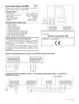
Drive Nameplate Data
The PowerFlex DC drive contains a data nameplate located on the side of
each drive that identifies the specific model number design, applicable AC
input power and DC output power data. All communication with Rockwell
Automation personnel concerning this product should include this
information.
Drive Frame Sizes
Similar PowerFlex DC drive sizes are grouped into frame sizes to simplify
spare parts ordering, dimensioning, etc. Refer to the Catalog Number
Explanation on page Preface-4 for a list of drive catalog numbers and their
respective frame sizes.
Reference Materials
The following manuals are recommended for general drive information:
For Allen-Bradley Drives Technical Support:
EXAMPLE ONLY
20P41AD4P1RA0NNN
Made in Italy
Output: 500VDC 4.1A REGEN 1.0HP
1 Min Overload Amps
3 Sec Overload Amps
MFD. in 2XXX on MMM DD
Cat No.
Input: 460VAC 50/60 Hz 3.3A 3 Phase
UL Type OPEN/IP20
Original Firmware V. 1.001
Serial Number: A23E0042
Series: A
Frame: A
6.2
8.2
I/O: 24VDC (Standard)
Ind. Cont.
Listed
C
R
US
DC Field:
Input: 460VAC 50/60 Hz 10A max. 1 Phase
Output: 360VDC 10A max.
Regulator Power: 115/230VAC 50/60 Hz 1.0/0.5A 1 Phase
Eq. 31KF
N223
Note: Certification
Marks Location.
Refer to the data
nameplate label
on your drive for
actual agency
certifications.
Title Publication Available Online at . . .
Preventive Maintenance of Industrial Control and
Drive System Equipment
DRIVES-TD001…
www.rockwellautomation.
com/literature
Safety Guidelines for the Application, Installation
and Maintenance of Solid State Control
SGI-1.1
A Global Reference Guide for Reading Schematic
Diagrams
100-2.10
Guarding Against Electrostatic Damage 8000-4.5.2
Title Online at . . .
Allen-Bradley Drives Technical Support www.ab.com/support/abdrives

PowerFlex Digital DC Drive User Manual - Publication 20P-UM001C-EN-P - July 2008
Overview p-3
Manual Conventions
• To help differentiate parameter names and LCD display text from other
text, the following conventions will be used:
– Parameter Names will appear in [brackets].
For example: [Armature Voltage].
– Display Text will appear in “quotes.” For example: “Enabled.”
• The following words are used throughout the manual to describe an
action:
General Precautions
Word Meaning
Can Possible, able to do something
Cannot Not possible, not able to do
something
May Permitted, allowed
Must Unavoidable, you must do this
Shall Required and necessary
Should Recommended
Should Not Not recommended
!
ATTENTION: This drive contains ESD (Electrostatic
Discharge) sensitive parts and assemblies. Static control
precautions are required when installing, testing, servicing or
repairing this assembly. Component damage may result if ESD
control procedures are not followed. If you are not familiar with
static control procedures, reference A-B publication 8000-4.5.2,
“Guarding Against Electrostatic Damage” or any other applicable
ESD protection handbook.
!
ATTENTION: An incorrectly applied or installed drive can
result in component damage or a reduction in product life. Wiring
or application errors, such as, undersizing the motor, incorrect or
inadequate AC supply, or excessive surrounding air temperatures
may result in malfunction of the system.
!
ATTENTION: Only qualified personnel familiar with DC drives
and associated machinery should plan or implement the
installation, start-up and subsequent maintenance of the system.
Failure to comply may result in personal injury and/or equipment
damage.
!
ATTENTION: An incorrectly applied or installed bypass system
can result in component damage or reduction in product life. The
most common causes are:
• Wiring AC line to drive output or control terminals.
• Improper bypass or output circuits not approved by
Allen-Bradley.
• Output circuits which do not connect directly to the motor.
Contact Allen-Bradley for assistance with application or wiring.

PowerFlex Digital DC Drive User Manual - Publication 20P-UM001C-EN-P - July 2008
p-4 Overview
Catalog Number
Explanation
Position
1-3 4 5 6 7 8-10 11 12 13 14 15 16
20P 4 1 A D 4P1 R N 0 N N N
abcdef gh i jkl
a
Drive
Code Type
20P PowerFlex DC
b
Motor Operation
Code Type
2 Two Quadrant Operation
4 Four Quadrant Operation
c
Input Type
Code Type
1 6 Pulse
2 12 Pulse
d
Enclosure
Code Enclosure Rating
Conform.
Coat
A IP20, NEMA/UL Type Open
B
IP43, NEMA/UL Type 1 -
Filter
No
G IP54, NEMA/UL Type 12
H
IP54, NEMA/UL Type 12 -
Fan/Filter
No
N IP00, NEMA/UL Type Open
e
Input Voltage
Code Voltage
B 230V ac
C 400V ac
D 460V ac
E 600V ac
F 690V ac
f1
230V, 60 Hz Input
Code Hp
Armature
Amps
Frame
Field
Amps
7P0 1.5 7 A 10
9P0 2 9 A 10
012 3 12 A 10
020 5 20 A 10
029 7.5 29 A 10
038 10 38 A 10
055 15 55 A 10
073 20 73 A 14
093 25 93 A 14
110 30 110 A 14
146 40 146 B 20
180 50 180 B 20
218 60 218 B 20
265 75 265 B 20
360 100 360 B 20
434 125 434 B 20
521 150 521 C 20
f2
460V, 60 Hz Input
Code Hp
Armature
Amps
Frame
Field
Amps
4P1 2 4.1 A 10
6P0 3 6 A 10
010 5 10 A 10
014 7.5 14 A 10
019 10 19 A 10
027 15 27 A 10
035 20 35 A 10
045 25 45 A 10
052 30 52 A 10
073 40 73 A 14
086 50 86 A 14
100 60 100 A 14
129 75 129 A 14
167 100 167 B 20
207 125 207 B 20
250 150 250 B 20
330 200 330 B 20
412 250 412 B 20
495 300 495 C 20
667 400 667 C 20
g
Field Supply
Code Type
A Three-Phase Regulated
F Fixed Field w/Economy
R Single-Phase Regulated
h
Packaging/Documentation
Code Shipping Carton User Manual
0No No
AYes Yes
NYes No
QNo Yes
i
HIM
Code Operator Interface
0 Blank Cover
Standard - for additional selections, refer to the
PowerFlex Digital DC Drive Technical Data,
publication 20P-TD001. . .
j
I/O Options
Code Control
A
I/O Expansion Card (4 Additional 24V
dc Digital Inputs & Outputs, 2 Analog
Outputs)
B
115V ac Conversion Card (8 Digital
Inputs & Outputs)
C
I/O Expansion Card + 115V ac
Conversion
N
None (8 - 24V dc Digital Inputs &
Outputs, 3 Analog Outputs and 2
Analog Inputs are Standard)
k
Communication Options
Code Description
N
None
l
Cabinet Options
Code Type
N None
No
No
No
Standard - for additional selections, refer to the
PowerFlex Digital DC Drive Technical Data,
publication 20P-TD001. . .

PowerFlex Digital DC Drive User Manual - Publication 20P-UM001C-EN-P - July 2008
Chapter 1
Installation and Wiring
This chapter provides information on mounting and wiring the PowerFlex
DC drive.
Most start-up difficulties are the result of incorrect wiring. Every precaution
must be taken to assure that the wiring is done as instructed. All items must
be read and understood before the actual installation begins.
Important:The PowerFlex DC drive is not
designed for use with multiple
motor applications.
For information on . . See page For information on. . See page
Mounting Considerations
1-2 Control Power Protection 1-11
Mounting Dimensions and Weights 1-3 General Grounding Requirements 1-12
Lifting PowerFlex DC Drives 1-5 Power Circuit Protection 1-13
Removing the Drive Covers 1-7 Cable and Wiring Recommendations 1-14
Line Reactors / Filters 1-9 Power Wiring 1-15
Using Contactors 1-9 I/O Wiring 1-32
!
ATTENTION: The following information is merely a guide for
proper installation. Rockwell Automation cannot assume
responsibility for the compliance or the noncompliance to any
code, national, local or otherwise for the proper installation of this
drive or associated equipment. A hazard of personal injury and/or
equipment damage exists if codes are ignored during installation.

PowerFlex Digital DC Drive User Manual - Publication 20P-UM001C-EN-P - July 2008
1-2 Installation and Wiring
Mounting Considerations
Operating Conditions and Temperatures
PowerFlex DC drives are designed to operate at 0° to 50° C surrounding air
temperature without derating. The drive must be mounted in a clean, dry
location. Contaminants such as oils, corrosive vapors and abrasive debris
must be kept out of the enclosure. NEMA/UL Type Open, IP20 enclosures
are intended for indoor use primarily to provide a degree of protection
against contact with enclosed equipment. These enclosures offer no
protection against airborne contaminants.
Minimum Mounting Clearances
Minimum clearance requirements (indicated in Figure 1.1) are intended to
be from drive to drive. Other objects can occupy this space; however,
reduced airflow may cause protection circuits to fault the drive. The drive
must be mounted in a vertical orientation as shown below and must not be
mounted at an angle greater than 30° from vertical. In addition, inlet air
temperature must not exceed the product specification.
Figure 1.1 Drive Enclosure Minimum Mounting Clearances
10 mm
10 mm
50 mm
(0.4 in.)
(0.4 in.) (2.0 in.)
10 mm
(0.4 in.)
150 mm (6.0 in.)
150 mm (6.0 in.)
150 mm (6.0 in.)
STS
PORT
MOD
NET A
NET B
STS
PORT
MOD
NET A
NET B
Airflow through
the drive must
not be impeded.

PowerFlex Digital DC Drive User Manual - Publication 20P-UM001C-EN-P - July 2008
Installation and Wiring 1-3
Mounting Dimensions and
Weights
The PowerFlex DC drive is available in a NEMA/UL Type Open, IP20
enclosure. Following all mounting instructions in order to ensure proper
operation.
Figure 1.2 Frame A Approximate Dimensions
Table 1.A Frame A Weights
!
ATTENTION: Remove all loose packing materials, including
the container(s) of desiccants (if any), from the drive enclosure
before mounting and energizing the drive.
ABCA1B1
mm (in.) mm (in.) mm (in.) mm (in.) mm (in.)
267 (10.5) 359 (14.0) 287 (11.3) 250 (9.8) 275 (10.8)
Drive Current Rating Code
Weight
Drive Drive & Packaging
230V 460V kg (lbs.) kg (lbs.)
7P0 4P1 8.4 (19.5) 10.5 (23.1)
9P0 6P0
012 010
020 014
– 019
029 027
038 035 8.8 (19.4) 11 (24.3)
055 045
– 052
073 073 10.8 (23.8) 13 (28.7)
093 086
110 100
– 129
A
B
A1
B1
C
STS
PORT
MOD
NET A
NET B

PowerFlex Digital DC Drive User Manual - Publication 20P-UM001C-EN-P - July 2008
1-4 Installation and Wiring
Figure 1.3 Frame B Approximate Dimensions
Table 1.B Frame B Weights
A A1A2B B1C
mm (in.) mm (in.) mm (in.) mm (in.) mm (in.) mm (in.)
311 (12.2) 275 (10.8) 16.5 (0.65) 388 (15.3) 375 (14.8) 350 (13.8)
Drive w/ND Rating Code
Weight
Drive Drive & Packaging
230V 460V kg (lbs.) kg (lbs.)
146 167 25.5 (56.2) 27.5 (60.6)
180 207
218 –
265 250 29.5 (65.0) 31.5 (69.4)
360 330 32 (70.5) 34 (75)
434 412
A
A1
B1
C
B
A2
STS
PORT
MOD
NET A
NET B

PowerFlex Digital DC Drive User Manual - Publication 20P-UM001C-EN-P - July 2008
Installation and Wiring 1-5
Figure 1.4 Frame C Approximate Dimensions
Table 1.C Frame C Weights
Lifting PowerFlex DC Drives
The dimensions and weights specified above must be taken into
consideration when mounting the device. Use the proper equipment to
safely lift and hold the weight of the drive while mounting.
A A1 B B1 B2 B3 B4 C
mm (in.) mm (in.) mm (in.) mm (in.) mm (in.) mm (in.) mm (in.) mm (in.)
521 (20.5) 499 (19.7) 511 (20.1) 400 (15.7) 200 (7.9) 55 (2.2) 56 (2.2) 416 (16.4)
B1
B2
B3
A
A1 C
B
B4
STS
PORT
MOD
NET A
NET B
Drive w/ND Rating Code
Weight - Regenerative Drives Weight - Non-regenerative Drives
Drive Drive & Packaging Drive Drive & Packaging
230V 460V kg (lbs.) kg (lbs.) kg (lbs.) kg (lbs.)
– 495 61 (134.5) 74 (163.1) 57 (125.7) 70 (154.3)
521 667 65 (143.3) 81 (178.6) 62 (136.7) 75 (165.3)
!
ATTENTION: To guard against possible personal injury or
equipment damage . . .
• Inspect all lifting hardware for proper attachment before lifting
the drive.
• Do Not allow any part of the drive or lifting mechanism to
make contact with electrically charged conductors or
components.
• Do Not subject the drive to high rates of acceleration or
deceleration while transporting to the mounting location or
when lifting.
• Do Not allow personnel or their limbs directly underneath the
drive when it is being lifted and mounted.

PowerFlex Digital DC Drive User Manual - Publication 20P-UM001C-EN-P - July 2008
1-6 Installation and Wiring
Mounting Frame C Drives
All lifting equipment and lifting components (hooks, bolts, lifts, slings,
chains, etc.) must have a minimum
lifting capacity of 453.6 kg (1,000 lb.).
Important:Verify that all mounting screws are properly tightened before
and after drive operation.
1. Verify the hole pattern on the panel to which the drive will be mounted.
Refer to Figure 1.4 on page 1-5
.
2. Insert, but do not tighten, one bolt in one of the top holes in the panel.
The bolt must be fully threaded into the panel before hanging the drive.
3. Insert the properly sized and rated lifting hooks into the holes on the
lifting flanges at the top of the drive. To limit the pull in forces on the
drive, the lifting devices connected to the hooks must be long enough to
make the angle between the chain or cable and a vertical line extending
up from the flange center less than 45 degrees as illustrated below.
Figure 1.5 Lifting Angle
4. Lift the drive into place on to the bolt installed in the panel.
5. Install the remaining five bolts into the panel. Tighten all bolts to a
torque of 22.6 N•m (200 lb•in).
Lifting flange
Angle Must Be Less
Than 45 Degrees

PowerFlex Digital DC Drive User Manual - Publication 20P-UM001C-EN-P - July 2008
Installation and Wiring 1-7
Removing the Drive Covers
The lower protective cover must be removed in order to access the drive’s
power and I/O terminals. The upper cover only needs to be removed to
install an optional communication adapter and service the drive. (Refer to
Installing a Communication Adapter on page E-1
for information.)
Frame A Drives
You must remove both the lower protective cover and the power terminal
cover on frame A drives to access the power terminals.
Remove the Power Terminal Cover
Remove the two screws as shown below and slide the cover down and off
the chassis.
Figure 1.6 Frame A Power Terminal Cover Removal

PowerFlex Digital DC Drive User Manual - Publication 20P-UM001C-EN-P - July 2008
1-8 Installation and Wiring
Remove the Lower Protective Cover
Remove the two screws as shown below and, while gently lifting along the
top edge, slide the cover down and off the chassis.
Figure 1.7 Frame A Lower Cover Removal
Frame B and C Drives
Loosen, but do not remove, the two screws that secure the bottom cover.
Then, slide the cover down until the screw heads line up with the key holes
and lift the cover off the chassis.
Figure 1.8 Frame B & C Drive Cover Removal
STS
PORT
MOD
NET A
NET B
Frame B Shown
/