Rockwell Automation PowerFlex 755TM Installation guide
- Category
- Mounting kits
- Type
- Installation guide

Installation Instructions
Original Instructions
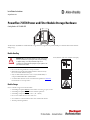
PowerFlex 755TM Power and Filter Module Storage Hardware
Catalog Number
20-750-MINV-ATIP
The PowerFlex® 755TM Power and Filter Module storage hardware is designed to help stabilize IGBT power modules and LCL filter modules
during storage.
Module Handling
• Do not use this storage hardware to transport modules.
• Module wheels are designed for module installation and removal only.
Do not use module wheels for transport.
• Only use the PowerFlex 750-Series service cart (20-750-MCART1) to
transport individual PowerFlex 755TM modules.
• See the PowerFlex 750-Series Service Cart Instructions, publication 750-IN105
for information on cart setup and use.
Module Storage
Choose a suitable storage location for the module.
• Surrounding atmosphere must
not contain volatile or corrosive gas, vapors, or dust.
• Surrounding atmosphere must
not contain conductive pollutants.
• Surrounding air temperature is -40…+70 °C (-40…+158 °F).
• Do not store modules in active isles or work areas.
• Store modules on a smooth and level surface clear of debris and obstacles.
• Avoid sloped and rough surfaces.
ATTENTION: IGBT power and LCL filter modules have a high center of gravity
and a tip-over hazard exists. To guard against death, serious personal injury,
or equipment damage, do not subject the module to high rates of
acceleration or deceleration while transporting. Do not push or pull above the
points indicated on the module.
This label, affixed to the module chassis, identifies the center of gravity.

Allen-Bradley, PowerFlex, Rockwell Automation, and Rockwell Software are trademarks of Rockwell Automation, Inc.
Trademarks not belonging to Rockwell Automation are property of their respective companies.
Rockwell Otomasyon Ticaret A.Ş., Kar Plaza İş Merkezi E Blok Kat:6 34752 İçerenköy, İstanbul, Tel: +90 (216) 5698400
Rockwell Automation maintains current product environmental information on its website at
http://www.rockwellautomation.com/rockwellautomation/about-us/sustainability-ethics/product-environmental-compliance.page
.
*PN-358143*
PN-358143
Publication 750-IN106A-EN-P - May 2016
Copyright © 2016 Rockwell Automation, Inc. All rights reserved. Printed in the U.S.A.
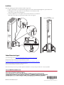
Installation
Perform the following steps with the module in its final storage location.
1. Align one of the supports to the threaded mounting holes on the back of module and hand tighten the captive thumb screws.
2. Hand tighten the two captive thumb screws that thread into the side wall of the module.
Repeat these steps with the remaining support.
3. Rotate the adjustable feet on each support counter-clockwise until the feet touch the floor.
Note : Raise the feet before you reposition the module or remove the supports.
Rockwell Automation Support
For technical support, visit http://www.rockwellautomation.com/support/overview.page.
1
2
2
2
3
Front View
Module with storage hardware installed.
-
 1
1
-
 2
2


Rockwell Automation PowerFlex 755TM Installation guide
- Category
- Mounting kits
- Type
- Installation guide
Ask a question and I''ll find the answer in the document
Finding information in a document is now easier with AI
Related papers
-
 Rockwell Automation PowerFlex 700S Migration Manual
-
 Rockwell Automation Allen-Bradley PowerFlex 750 Series Installation Instructions Manual
-
 Rockwell Automation Allen-Bradley PowerFlex 750 Series User manual
-
 Rockwell Automation Allen-Bradley PowerFlex 750 Series User manual
-
 Rockwell Automation Allen-Bradley PowerFlex Active Front End Series User manual
-
 Rockwell Automation Allen-Bradley PowerFlex 700AFE Hardware Service Manual
-
 Rockwell Automation Allen-Bradley Kinetix 5700 Series Application Technique
-
 Rockwell Automation Allen-Bradley DriveGuard 20D-P2-DG01 User manual
-
Rockwell Automation Allen-Bradley Logix5000 Quick start guide
-
 Rockwell Automation PowerFlex 700S User manual


Other documents
-
Allen-Bradley 20-750-MCART2 Installation Instructions Manual
-
-
-
-
-
-
-
Allen-Bradley PowerFlex 20-HIM-A6 User manual
-
-