Page is loading ...

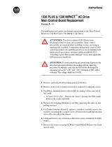
PowerFlex 70/700/753/755 & 1336 Drive – Maintenance Schedule (For 24/7 Operation)
Years
0
1
2
3
4
5
6
7
8
9
10
11
12
13
14
15
16
17
18
19
20
Commissioning Activities
S
Air-cooling
system
Door Mounted Air Filters
C / R
C / R
C / R
C / R
C / R
C / R
C / R
C / R
C / R
C / R
C / R
C / R
C / R
C / R
C / R
C / R
C / R
C / R
C / R
C / R
C / R
Entire Main Cooling Fan Motor *
I
I
R
I
I
R
I
I
R
R
I
R
I
I
R
I
I
R
I
I
Entire Redundant Cooling Fan Motor *
I
I
I
I
I
I
I
I
I
R
I
I
I
I
I
I
I
I
I
I
Small Aux. Cooling Fans "Caravel"
I
I
R
I
I
R
I
I
R
R
I
R
I
I
R
I
I
R
I
I
Fan caps
I
I
R
I
I
R
I
I
R
I
I
R
I
I
R
I
I
R
I
I
Liquid-cooling
system
Mesh Filters
C
C
C
C
C
C
C
C
C
C
C
C
C
C
C
C
C
C
C
C
C
De-ionizing Filter Cartridge
R
R
R
R
R
R
R
R
R
R
R
R
R
R
R
R
R
R
R
R
R
Coolant
R
R
R
R
R
R
R
R
R
R
R
R
R
R
R
R
R
R
R
R
All Fittings/Connections/Hose Clamps
I
I
I
I
I
I
I
I
I
I
I
I
I
I
I
I
I
I
I
I
Cooling Pump Motors/Pumps
I
I
I
I
R
I
I
I
I
R
I
I
I
I
R
I
I
I
I
R
Thermostatic Valve Element
I
R
I
R
I
R
I
R
I
R
I
R
I
R
I
R
I
R
I
R
Power Switching
Components
Power Devices (IGBTs/SCRs)
I
I
I
I
I
I
I
I
I
R
I
I
I
I
I
I
I
I
I
R
Electrolytic Bus Capacitors *
I
I
R
I
R
R
I
I
R
R
I
R
I
I
R
I
I
R
I
R
Snubber Resistors/Sharing
Resistors/HECS
I
I
I
I
I
I
I
I
I
I
I
I
I
I
I
I
I
I
I
I
Rectifier Snubber Capacitors
I
I
R
I
R
R
I
I
R
R
I
R
I
I
R
I
I
R
I
R
Inverter Snubber Capacitors
I
I
R
I
R
R
I
I
R
R
I
R
I
I
R
I
I
R
I
R
Integrated Gate Driver Power Supply
I
I
RFB/R
I
I
I
I
I
RFB/R
I
I
RFB/R
I
I
RFB/R
I
I
RFB/R
I
I
Integral
Magnetics/Power
Filters
Isolation Transformer/Line Reactor
I
I
M
I
I
M
I
I
M
I
I
M
I
I
M
I
I
M
I
I
DC Link/Common-Mode Choke
I
I
M
I
I
M
I
I
M
I
I
M
I
I
M
I
I
M
I
I
Line/Motor Filter Capacitors
I
I
M
I
I
M
I
I
M
I
I
M
I
I
M
I
I
M
I
I
Control Cabinet
Components
AC/DC and DC/DC Power Supplies
I
I
RFB/R
I
I
RFB/R
I
I
RFB/R
I
I
RFB/R
I
I
RFB/R
I
I
I
I
I
Control Boards
I
I
I
I
I
I
I
I
I
I
I
I
I
I
I
I
I
I
I
I
Batteries (DCBs and CIB)
I
R
I
R
I
R
I
R
I
R
I
R
R
I
I
R
I
R
I
R
Batteries (UPS)
I
I
R
I
I
R
I
I
R
I
I
R
I
I
I
R
I
I
I
R
Enhancements
Firmware
-
-
Rv
-
-
Rv
-
-
Rv
-
-
Rv
-
-
Rv
-
-
Rv
-
-
Hardware
-
-
Rv
-
-
Rv
-
-
Rv
-
-
Rv
-
-
Rv
-
-
Rv
-
-
Operational
Conditions
Parameters
I
I
Rv
I
I
Rv
I
I
Rv
I
I
Rv
I
I
Rv
I
I
Rv
I
I
Variables
I
I
Rv
I
I
Rv
I
I
Rv
I
I
Rv
I
I
Rv
I
I
Rv
I
I
Application Concerns
I
I
Rv
I
I
Rv
I
I
Rv
I
I
Rv
I
I
Rv
I
I
Rv
I
I
Spare Parts
Inventory/Needs
I
I
Rv
I
I
Rv
I
I
Rv
I
I
Rv
I
I
Rv
I
I
Rv
I
I
Notes:
Load Profile and other Operating/Environmental Conditions greatly affect Reliability of the Drive.

Maintenance Schedule, Cont’d
Rockwell recognizes that following a defined maintenance schedule will deliver the maximum product availability. By rigorously following this maintenance schedule, the Customer can expect the highest possible
uptime. This Annual Preventative Maintenance Program includes a visual inspection of all drive components visible from the front of the unit, resistance checks on the power components, power supply voltage level
checks, general cleaning and maintenance, checking of all accessible power connections for tightness, and other tasks.
Schedule Codes
I – Inspection
This indicates that the component should be inspected for signs of excessive accumulation of dust/dirt/etc. or external damage (e.g. looking at Filter Capacitors for bulges in the case, inspecting the heatsinks for
debris clogging the air flow path, etc.).
M – Maintenance
This indicates a maintenance task that is outside the normal preventative maintenance tasks, and can include the inductance testing of Line Reactors/DC Links, or the full testing of an isolation transformer.
R – Replacement
This indicates that the component has reached its mean operational life, and should be replaced to decrease the chance of component failure. It is very likely that components will exceed the design life in the drive,
and that is dependent on many factors such as usage, heating, etc.
C – Cleaning
This indicates the cleaning of a part that can be reused, and refers specifically to the door-mounted air filters in the liquid-cooled drives and some air-cooled drives.
Rv – Review
This refers to a discussion with Rockwell Automation to determine whether any of the enhancements/changes made to the Drive Hardware and Control would be valuable to the application.
RFB/R – Refurbishment/Replacement
The parts can be refurbished at lower cost OR the parts can be replaced with new ones.
MAINTENANCE OF INDUSTRIAL CONTROL EQUIPMENT
ATTENTION: Servicing energized Industrial Control Equipment can be hazardous. Severe injury or death can result from electrical shock, bump, or unintended actuation of controlled equipment. Recommended
practice is to disconnect and lockout control equipment from power sources, and release stored energy, if present. Refer to National Fire Protection Association Standard No. NFPA70E, Part II and (as applicable)
OSHA rules for Control of Hazardous Energy Sources (Lockout/Tagout) and OSHA Electrical Safety Related Work Practices for safety related work practices, including procedural requirements for lockout-tagout, and
appropriate work practices, personnel qualifications and training requirements where it is not feasible to de-energize and lockout or tagout eectric circuits and equipment before working on or near exposed circuit
parts.

Maintenance Schedule, Cont’d
Other Specific Inspection related Details
Periodic Inspection - Industrial control equipment should be inspected periodically. Inspection intervals should be based on environmental and operating conditions and adjusted as indicated by experience. An
initial inspection within 3 to 4 months after installation is suggested. See National Electrical Manufacturers Association NEMA) Standard No. ICS 1.3, Preventive Maintenance of Industrial Control and Systems
Equipment, for general guidelines for setting-up a periodic maintenance program. Some specific guidelines for Rockwell Automation products are listed below.
Contamination - If Inspection reveals that dust, dirt, moisture or other contamination has reached the control equipment, the cause must be eliminated. This could indicate an incorrectly selected or ineffective
enclosure, unsealed enclosure openings (conduit or other) or incorrect operating procedures. Replace any improperly selected enclosure with one that is suitable for the environmental conditions - refer to NEMA
Standard No. 250, Enclosures for Electrical Epuipment for enclosure type descriptions and test criteria. Replace any damaged or embrittled elastomer seals and repair or replace any other damaged or
malfunctioning parts (e.g., hinges, fasteners, etc.). Dirty, wet or contaminated control devices must be replaced unless they can be cleaned effectively by vacuuming or wiping. Compressed air is not recommended
for cleaning because it may displace dirt, dust, or debris into other parts or equipment, or damage delicate parts.
Cooling Devices - Inspect blowers and fans used for forced air cooling. Replace any that have bent, chipped, or missing blades, or if the shaft does not turn freely. Apply power momentarily to check operation. If
unit does not operate, check and replace wiring, fuse, or blower or fan motor as appropriate. Clean or change air fitters as recommended in the product manual. Also, clean fins of heat exchangers so convection
cooling is not impaired.
Hazardous Location Enclosures - ATTENTION: Explosion hazard. Always disconnect power before opening enclosures in hazardous locations. Close and secure such enclosures before reapplying power.
NEMA Types 7 and 9 enclosures require careful handling so machined flanges do not get damaged. For removable covers, remove the cover and set aside with machined surface up. For hinged covers, open the
cover fully and restrain in the full open position H necessary. Clean and examine the flanges on both the body and cover before reassembly. If there are scratches, nicks, grooves or rust on the mating surfaces,
replace the body or cover as necessary. Examine all bolts and replace any that have damaged threads. Also check mating threads for damage and replace enclosure it necessary. Covers and bodies of some
enclosures are manufactured as matched sets (not interchangeable). The manufacturer should be consulted before replacing a cover or body unless it is specified by the manufacturer as interchangeable.
Operating Mechanisms - Check for proper functioning and freedom from sticking or binding. Replace any broken, deformed or badly wont parts or assemblies according to individual product renewal parts lists.
Check for and retighten securely any loose fasteners. Lubricate if specified in individual product instructions. Note: Allen-Bradley magnetic starters, contactors and relays are designed to operate without
lubrication-do not lubricate these devices because oil or grease on the pole faces (mating surfaces) of the operating magnet may cause the device to stick in the "ON" mode. Sane parts of other devices are factory
lubricated-if lubrication during use or maintenance of these devices is needed, it will be specified in their individual instructions. if in doubt, consult your nearest Allen-Bradley Sales Office for information.
Contacts - Check contacts for excessive wear and dirt accumulations. Vacuum or wipe contacts with a soft cloth ?f necessary to remove dirt. Contacts are not harmed by discoloration and slight pitting. Contacts
should never be flied, as dressing only shortens contact life. Contact spray cleaners should not be used as their residues on magnet pole faces or in operating mechanisms may cause sticking, and on contacts can
interfere with electrical continuity. Contacts should only be replaced otter silver has become badly wont. Always replace contacts in complete sets to avoid misalignment and uneven contact pressure.

Maintenance Schedule, Cont’d
Vacuum Contactors - Contacts of vacuum contactors are not visible, so contact wear must be checked indirectly. Vacuum bottles should be replaced when:
1. The estimated number of operations equals one million, or
2. The contact life line indicator shows need for replacement, or
3. The vacuum bottle integrity tests show need for replacement. Replace all vacuum bottles in the contactor at the same time to avoid misalignment and uneven contact wear. If the vacuum battles do not require
replacement, check and adjust overtravel to the value listed on the maintenance instructions.
Terminals - Loose connections in power circuits can cause overheating that can lead to equipment malfunction or failure. Loose connections in control circuits can cause control malfunctions. Loose bonding or
grounding connections can Increase hazards of electrical shock and contribute to electromagnetic interference (EMI). Check the tightness of all terminals and bus bar connections and tighten securely any loose
connections. Replace any parts or wiring damaged by overheating, and any broken wires or bonding straps.
Arc Hood - Check for cracks, breaks, or deep erosion. Arc hoods and arc chutes should be replaced if damaged or deeply eroded.
Coils - If a cog exhibits evidence of overheating (cracked, melted or burned insulation), it must be replaced. In that event, check for and correct overvoltage or undervoltage conditions, which can cause coil
failure. Be sure to dean any residues of melted coil insulation from other parts of the device or replace such parts.
Batteries - Replace batteries periodically as specified in product manual or if a battery shows signs of electrolyte leakage. Use tools to handle batteries that have leaked electrolyte; most electrolytes are corrosive
and can cause burns. Dispose of the old battery in accordance with instructions supplied with the new battery or as specified In the manual for the product.
Pilot Lights - Replace any burned out lamps or damaged lenses. Photoelectric Switches-The lenses of photoelectric switches require periodic cleaning with a soft dry cloth. Reflective devices used in conjunction
with photoelectric switches also require periodic cleaning. Do not use solvents or cleaning agents on the lenses or reflectors. Replace any damaged lenses and reflectors.
Solid State Devices
-ATTENTION: Use of other than factory recommended test equipment for solid state controls may result in damage to the control or test equipment or unintended actuation of the controlled equipment. Refer to
paragraph titled HIGH VOLTAGE TESTING.
Solid state devices require little more than a periodic visual inspection. Discolored, charred or burned components may indicate the need to replace the component or circuit board. Necessary replacements should
be made only at the PC board or plug-in component level. Printed circuit boards should be inspected to determine whether they are properly seated in the edge board connectors. Board locking tabs should also be
in place. Solid state devices must also be protected from contamination, and cooling provisions must be maintained - refer to paragraphs titled CONTAMINATION and COOLING DEVICES. Solvents should not be used
on printed circuit boards.
High Voltage Testing - High voltage insulation resistance (IR) and dielectric withstanding voltage (DWV) tests should not be used to check solid state control equipment. When measuring IR or DWV of electrical
equipment such as transformers or motors, a solid state device used for control or monitoring must be disconnected before performing the test. Even though no damage is readily apparent after an IR or DWV test,
the solid state devices are degraded and repeated application of high voltage can lead to failure.

Maintenance Schedule, Cont’d
Locking and Interlocking Devices - Check these devices for proper working condition and capability of performing their Intended functions. Make any necessary replacements only with Allen-Bradley renewal parts
or kits. Adjust or repair only in accordance with Allen-Bradley Instructions.
Maintenance After a Fault Condition - Opening of the short circuit protective device (such as fuses or circuit breakers) in a properly coordinated motor branch circuit is an indication of a fault condition in excess
of operating overload. Such conditions can cause damage to control equipment. Before restoring power, the fault condition must be corrected and any necessary repairs or replacements must be made to restore
the control equipment to good working order. Refer to NEMA Standards Publication No. ICS-2, Part ICS2-302 for procedures. Replacements-Use only replacement parts and devices recommended by Allen-Bradley to
maintain the integrity of the equipment Make sure the parts are properly matched to the model, series and revision level of the equipment Final Check Out - After maintenance or repair of industrial controls,
always test the control system for proper functioning under controlled conditions; that avoid hazards in the event of a control malfunction. For additional information, refer to NEMA ICS 1.3, PREVENTIVE
MAINTENANCE OF INDUSTRIAL CONTROL AND SYSTEMS EQUIPMENT, published by the National Electrical Manufacturers Association, and NFPA70B, ELECTRICAL EQUIPMENT MAINTENANCE, published by the National
Fire Protection Association.
/