Page is loading ...

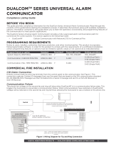
CellCom
TM
SERIES UNIVERSAL ALARM
COMMUNICATOR
Compliance Listing Guide
BEFORE YOU BEGIN
This guide provides compliance information for the CellCom Series Universal Alarm Communicator. The CellCom‑LTE‑V
Series Universal Alarm Communicator provides a fully supervised alarm communication path for any burglary,
commercial fire, or residential fire control panel. DMP recommends that you read through the contents of this guide
before starting the installation process. It describes the functions along with available installation options. Information
contained in this guide allows you to learn the operation, functionality, and programming features of the communicator
to meet specific applications. This guide covers all the requirements for installing the CellComSLCF and CellComF‑LTE‑V
Universal Alarm Communicators for Commercial Fire installations. This document applies to the following models:
• CellComSLC CDMA Cellular Communicator
• CellComSLCZ CDMA Cellular Communicator with Z‑Wave
• CellComSLCF CDMA Cellular Communicator for Commercial Fire
• CellCom‑LTE‑V LTE Cellular Communicator
• CellComZ‑LTE‑V LTE Cellular Communicator with Z‑Wave
• CellComF‑LTE‑V LTE Cellular Communicator for Commercial Fire
PROGRAMMING REQUIREMENTS
System Programming Option Requirements
Notice to users, installers, authorities that have jurisdiction, and other involved parties: This product incorporates
field‑programmable software. In order for the product to comply with the requirements of a certificated installation,
certain programming features or options must be limited to specific values or not used at all as indicated below.
PROGRAM FEATURE OR OPTION STANDARD PERMITTED? POSSIBLE SETTINGS SETTINGS PERMITTED
System Reports, RESTORAL ANSI/UL 864 Y NO, YES, DISARM YES, DISARM
Communication, CHECKIN MINUTES ANSI/UL 864 Y 3‑250 3‑58
Output Options, COMM FAIL OUT ANSI/UL 864 Y 0, 1, 2 1, 2
APPLICATIONS
CID
Dialer Connection
Directly connect the tip and ring from the control panel to the communicator. See Figure 1. This connection captures
Contact ID messages from any fire panel that are based on the SIA communication standard DC‑05‑1999.09‑DCS.
Messages are then formatted into a Serial 3 message and sent to a DMP Model SCS‑1R Receiver or SCS‑VR Receiver.
Note: CID Dialer Connection cannot be used when using Zone 4 Bell Connection. Do not connect telephone
company wires to the communicator. Remove any connected telephone company wires from the control panel.
Figure 1: CellCom Series Wiring Diagram for Tip and Ring Connection
Use 18-22 AWG for
Power Supply connection
Control Panel Tip
Control Panel Ring
12VDC Aux. Output
+
-
Ground
Control Panel
The panel or separate power
supply must be 12 Volt Regulated
and Power Limited.
Telephone
Jack
Connector
Bell -
Bell +
RESET
S1
LOAD
S2
BAT
S
N
+12 G Z1 Z2 Z4-Z4+GZ3 RTO2O1
RB
J8
J26
J9
S1
S2
S3
MODEL
CellComSLC

2 CellCom SERIES COMPLIANCE LISTING GUIDE | DIGITAL MONITORING PRODUCTS
COMPLIANCE
CellComSLCF and CellComF-LTE-V Commercial Fire Communicator Installation
ANSI/UL 864
Fire Protective Signaling Systems using Internet/Intranet/Cell Networks
A Performance Based Technologies system as defined in UL 864 10th Edition may be configured as CELL Primary with
or without a backup path. The system may be configured as the following:
Path 1 Type CELL Primary with no Backup
PATH 1 PROGRAMMING
Comm Type = CELL Checkin Min = 58
Path Type = Primary Failtime Min = 60
Test Rpt = No
Checkin = Yes
Model 685-R Back Box Installation
For Commercial Fire applications using the CellComSLCF or the
CellComF‑LTE‑V and the included red plastic Model 685‑R Back Box,
mount the Back Box to the wall with the 1” #6 screws included with
the fire communicator. Mount the fire communicator to the back box
with the 1/2” #6 screws. See Figure 2. Locate the fire communicator
within 20 feet of the control panel and route all wire in conduit.
CellComSLCF and CellComF-LTE-V for FACP
Communication Fail Output
For Future Use
# 6 Screws Included
with Backbox
Figure 2: Model 685-R Back Box Installation
Figure 3: CellComSLCF and CellComF-LTE-V
Wiring Diagram for FACP
24VDC Applications:
For 24VDC applications using the fire communicator, connect a
keypad using a Model 330‑24 4‑wire programming harness with
in‑line resistor.
Output 1:
Output 1 must be programmed as a Comm Fail output in Output
Options.
Installation Length:
Must be installed in conduit from the fire panel to the 685‑R
conduit box and located within 20 feet.
FACP Zone Input:
Program FACP Zone Input to indicate a communication trouble
locally.
+DC G Z1 Z2 Z3 G Z4+ Z4- O1 O2 T R
RB
J8
S3
J9
RESET
LOAD
S1
S2
CellComF-LTE-V
{
{
Main Fire Alarm
Control Panel (FACP)
FACP Zone Input
FACP Zone Input
Connect to terminal with
lowest voltage
Use EOL specified
by FACP
12/24VDC Aux Output
Ground
Output 1
+DC G Z1 Z2 Z3 G Z4+ Z4- O1 O2 T R
CellComSLCF/
CellComF-LTE-V

DIGITAL MONITORING PRODUCTS | CellCom SERIES COMPLIANCE LISTING GUIDE 3
NEW YORK CITY (FDNY) SPECIFICATIONS
Introduction
The programming specifications contained in this section must be completed when installing the CellComSLCF or
CellComF‑LTE‑V and iCOMSLF for New York City (FDNY) fire alarm communicator installations for IP communication
applications. Refer to the FDNY Certificate of Approval #6238 for the complete conditions of approval.
Network and Cellular Communication, Primary and Secondary
When installed as a central station Internet (Network) communicator or slave transmitter, both primary and secondary
channels of communication shall be required and shall meet the conditions below. Network communication (iComSLF)
shall be used as the primary channel of communication to the Central Station and a Cellular Communicator
(CellComSLCF or CellComF‑LTE‑V) shall be used as the secondary channel of communication or in reverse order: Cellular
Communicator (CellComSLCF or CellComF‑LTE‑V) as the primary channel and Network connection (iComSLF) as the
secondary channel.
iComSLF Primary and CellComSLCF or CellComF-LTE-V Backup Programming
iComSLF PROGRAMMING CellComSLCF or CellComF-LTE-V PROGRAMMING
Comm Type = NET Comm Type = CELL
Checkin Min = 5 Checkin Min = 5
Failtime Min = 5 Failtime Min = 5
Test Rpt = Yes Test Rpt = Yes
Test Freq = 1 Dy Test Freq = 1 Dy
CellComSLCF or CellComF-LTE-V Primary and iComSLF Backup Programming
CellComSLCF or CellComF-LTE-V PROGRAMMING iComSLF PROGRAMMING
Comm Type = CELL Comm Type = NET
Checkin Min = 5 Checkin Min = 5
Failtime Min = 5 Failtime Min = 5
Test Rpt = Yes Test Rpt = Yes
Test Freq = 1 Dy Test Freq = 1 Dy
Wiring
All wiring must be in accordance with NEC, ANSI, and NFPA 70. All network cabling must be installed in accordance with
NFPA 70 for communication circuits.
Additional Requirements
Program and install the equipment to comply with NFPA basic fire requirements. Refer to the Universal Fire Alarm
Specifications and ANSI/UL 864 Specifications in this document.
Z-Wave
Note: Z‑Wave functionality has not been evaluated by UL.

Designed, engineered,
and manufactured in
Springfield, Missouri using U.S.
and global components.
LT-1620 1.02 18512
INTRUSION • FIRE • ACCESS • NETWORKS
2500 North Partnership Boulevard
Springfield, Missouri 65803-8877
800.641.4282 | DMP.com
Certifications
Cellular
• LTE FCC Part 15 ID: RI7ME910C1NV
CellComSLC, CellComSLCZ, CellCom-LTE-V,
CellComZ-LTE-V
FCC Part 15 ID: CCKPC0163
IC: 5251A‑PC0163
Underwriters Laboratory (UL) Listed
• ANSI/UL 1610 Central Station Burglar (Cellular)
• ANSI/UL 1023 Household Burglar
• ANSI/UL 985 Household Fire Warning (CID Capture)
CellComSLCF, CellComF-LTE-V
Underwriters Laboratory (UL) Listed
• ANSI/UL 864 Fire Protective Signaling Systems
(CID Capture)
Specifications
Primary Power Nominal 12VDC or 24VDC
Current Draw at 12VDC:
Standby 64mA
Alarm 109 mA (Peak Cellular Communication)
Current Draw at 24VDC:
Standby 30mA
Alarm 82 mA (Peak Cellular Communication)
FCC NOTICE
This device complies with Part 15 of the FCC Rules. Ax the included FCC label to the exterior of the panel enclosure in
plain sight. Operation is subject to the following two conditions:
1. This device may not cause harmful interference, and
2. this device must accept any interference received, including interference that may cause undesired operation.
Changes or modifications made by the user and not expressly approved by the party responsible for compliance could
void the user’s authority to operate the equipment. The antenna(s) used for this transmitter must be installed to provide
a separation distance of at least 20 cm from all persons.
Note: This equipment has been tested and found to comply with the limits for a Class B digital device, pursuant to
part 15 of the FCC Rules. These limits are designed to provide reasonable protection against harmful interference
in a residential installation. This equipment generates, uses, and can radiate radio frequency energy and, if not
installed and used in accordance with the instructions, may cause harmful interference to radio communications.
However, there is no guarantee that interference will not occur in a particular installation. If this equipment does
cause harmful interference to radio or television reception, which can be determined by turning the equipment o
and on, the user is encouraged to try to correct the interference by one or more of the following measures:
• Reorient or relocate the receiving antenna.
• Increase the separation between the equipment and receiver.
• Connect the equipment into an outlet on a circuit dierent from that to which the receiver is connected.
• Consult the dealer or an experienced radio/TV technician for help.
If necessary, the installer should consult the dealer or an experienced radio/television technician for additional
suggestions. The installer may find the following booklet, prepared by the Federal Communications Commission, helpful:
“How to identify and Resolve Radio‑TV Interference Problems.”
This booklet is available from the U.S. Government Printing Oce, Washington D.C. 20402
Stock No. 004‑000‑00345‑4
Information furnished by DMP is believed to be accurate and reliable.
This information is subject to change without notice.
CellCom SERIES UNIVERSAL ALARM
COMMUNICATOR
/