Page is loading ...

CELLCOMSL
™
SERIES CELLULAR
ALARM COMMUNICATOR
INSTALL / PROGRAMMING GUIDE

FCC NOTICE
This equipment has been tested and found to comply with the limits for a Class B digital device, pursuant to part
15 of the FCC Rules. These limits are designed to provide reasonable protection against harmful interference
in a residential installation. This equipment generates, uses and can radiate radio frequency energy and, if not
installed and used in accordance with the instructions, may cause harmful interference to radio communications.
However, there is no guarantee that interference will not occur in a particular installation. If this equipment does
cause harmful interference to radio or television reception, which can be determined by turning the equipment off
and on, the user is encouraged to try to correct the interference by one or more of the following measures:
• Reorient or relocate the receiving antenna.
• Increase the separation between the equipment and receiver.
• Connect the equipment into an outlet on a circuit different from that to which the receiver is connected.
• Consult the dealer or an experienced radio/TV technician for help.
Changesormodicationsnotexpresslyapprovedbythepartyresponsibleforcompliancecouldvoidtheuser’s
authority to operate the equipment.
If necessary, the installer should consult the dealer or an experienced radio/television technician for additional
suggestions.Theinstallermayndthefollowingbooklet,preparedbytheFederalCommunicationsCommission,
helpful:
“How to identify and Resolve Radio-TV Interference Problems.”
ThisbookletisavailablefromtheU.S.GovernmentPrintingOfce,WashingtonD.C.20402
StockNo.004-000-00345-4
©2014DigitalMonitoringProducts,Inc.
InformationfurnishedbyDMPisbelievedtobeaccurateandreliable.
This information is subject to change without notice.
Theantenna(s)usedforthistransmittermustbeinstalledtoprovideaseparationdistanceofatleast20cmfrom
all persons.
THISDEVICECOMPLIESWITHPART15OFTHEFCCRULES.OPERATIONISSUBJECTTOTHEFOLLOWINGTWO
CONDITIONS:(1)THISDEVICEMAYNOTCAUSEHARMFULINTERFERENCE,AND(2)THISDEVICEMUSTACCEPTANY
INTERFERENCERECEIVED,INCLUDINGINTERFERENCETHATMAYCAUSEUNDESIREDOPERATION.
Industry Canada
ThisdevicecomplieswithIndustryCanadalicense-exemptRSSstandard(s).Operationissubjecttothefollowing
twoconditions:(1)thisdevicemaynotcauseinterference,and(2)thisdevicemustacceptanyinterference,
including interference that may cause undesired operation of the device.
Caution Notes
Throughoutthisguideyouwillseecautionnotescontaininginformationyouneedtoknowwheninstalling
the
c
ommunicator.Thesecautionsareindicatedwithayieldsign.Wheneveryouseeacautionnote,make
sure you completely read and understand its information. Failing to follow the caution note can cause
damage to the equipment or improper operation of one or more components in the system.

CellComSL
Series Communicator Install/Programming Guide Digital Monitoring Products
iii
TABLE OF CONTENTS
Table of Contents
Description .............................................................................................. 1
What is Included ............................................................................................................... 1
System Components ............................................................................... 1
1.1 Terminals (J9).......................................................................................................... 1
Power Connection Terminals ..................................................................................... 1
Standby Battery ...................................................................................................... 1
Zones 1-3 ............................................................................................................... 1
Zone 4 .................................................................................................................... 2
Open-Collector Outputs ............................................................................................ 2
Dialer Connection .................................................................................................... 2
1.2 Battery Connection (BAT J26) ................................................................................... 2
System Battery ........................................................................................................ 2
Battery Supervision .................................................................................................. 3
1.3 Programming Connection (PROG J8) ......................................................................... 3
1.4 Tamper (C3) ............................................................................................................ 3
1.5 Reset Button ........................................................................................................... 3
1.6 Load Button ............................................................................................................ 3
Mounting the CellComSL Series Communicator ..................................... 4
2.1 Selecting a Location ................................................................................................. 4
Applications ............................................................................................ 5
3.1
Dialer Connection ......................................................................................................5
3.2 Zones 1 - 3 and Outputs ........................................................................................... 5
3.3 Zone 4 and Outputs ................................................................................................. 6
3.4 Virtual Keypad App ................................................................................................. 6
Z-Wave Setup .......................................................................................... 7
User Code Level: Master only. .................................................................................. 7
5.1 Add Z-Wave Devices (ADD) ...................................................................................... 7
5.2 List Z-Wave Devices (LIST) ....................................................................................... 7
5.3 RENAME Z-Wave Devices .......................................................................................... 7
5.4 STATUS of Z-Wave Devices ....................................................................................... 8
5.5 Remove Z-Wave Devices (REMOVE) .......................................................................... 8
5.6 Favorites (FAV) ........................................................................................................ 8
5.7 Adding a FAVORITE ................................................................................................. 8
5.8 ADD Devices to FAVORITES ...................................................................................... 8
5.9 Device Settings in FAVORITES .................................................................................. 9
Lights ..................................................................................................................... 9
Locks ...................................................................................................................... 9
Thermostats ............................................................................................................ 9
5.10 EDIT Devices in FAVORITES ..................................................................................... 9
5.11 REMOVE Devices from FAVORITES ...........................................................................10
5.12 Transfer Controller (XFER) .......................................................................................10
Transfer Operation: .................................................................................................10
5.13 Rediscover (REDISC) ...............................................................................................10
Programming the
CellComSL
Series Cellular Alarm Communicator ..... 11
6.1 Before You Begin ....................................................................................................11
Programming Information Sheet ..............................................................................11
6.2 Getting Started .......................................................................................................11
Initializing the
CellComSL
Series ..............................................................................11
Accessing the Programmer ......................................................................................11
6.3 Programming Menu .................................................................................................11
6.4 Reset Timeout ........................................................................................................12
6.5 Special Keys ...........................................................................................................12
COMMAND (CMD) Key ............................................................................................12
Back Arrow (<—) Key ...............................................................................................12

Digital Monitoring Products
CellComSL
Series Communicator Install/Programming Guide
iv
TABLE OF CONTENTS
Select Keys/Areas ...................................................................................................12
6.6 Entering Alpha Characters .......................................................................................12
6.7 Entering Non-Alpha Characters ................................................................................13
6.8 Keypad Displays Current Programming .....................................................................13
Initialization .......................................................................................... 14
7.1 Initialization ...........................................................................................................14
7.2 Clear All Codes .......................................................................................................14
7.3 Clear All Schedules ..................................................................................................14
7.4 Clear Events ...........................................................................................................14
7.5 Clear Zone Programming .........................................................................................14
7.6 Clear Communication ..............................................................................................14
7.7 Set to Factory Defaults ............................................................................................14
Communication ..................................................................................... 15
8.1 Communication .......................................................................................................15
8.2 Account Number .....................................................................................................15
8.3 Transmission Delay .................................................................................................15
8.4 Communication Type ...............................................................................................15
8.5 Test Time ...............................................................................................................15
8.6 Cell Check In ..........................................................................................................15
8.7 Fail Time ................................................................................................................15
8.8 Receiver 1 Programming .........................................................................................15
8.9 Alarm Reports.........................................................................................................15
8.10 Supervisory/Trouble Reports ....................................................................................15
8.11 Opening/Closing and User Reports ...........................................................................15
8.12 Test Report.............................................................................................................15
8.13 First IP Address ......................................................................................................15
8.14 First IP Port ............................................................................................................16
8.15 Second IP Address ..................................................................................................16
8.16 Second IP Port ........................................................................................................16
8.17 Receiver 2 Programming .........................................................................................16
8.18 Alarm Reports.........................................................................................................16
8.19 Supervisory/Trouble Reports ....................................................................................16
8.20 Opening/Closing and User Reports ...........................................................................16
8.21 Test Report.............................................................................................................16
Messaging Setup ................................................................................... 16
9.1 Messaging Setup ...................................................................................................16
9.2 Enable Messaging ...................................................................................................16
9.3 System Name .........................................................................................................17
9.4 Destination 1 ..........................................................................................................17
9.5 Destination 1 User Number ......................................................................................17
9.6 Destination 2 ..........................................................................................................17
9.7 Destination 2 User Number ......................................................................................17
9.8 Destination 3 ..........................................................................................................17
9.9 Destination 3 User Number ......................................................................................17
9.10 O/C E-mail .............................................................................................................17
9.11 O/C SMS ................................................................................................................17
9.12 Monthly Limit .........................................................................................................17
Remote Options .................................................................................... 18
10.1 Remote Options ......................................................................................................18
10.2 Remote Key ............................................................................................................18
10.3 Remote Disarm .......................................................................................................18
System Reports ..................................................................................... 18
11.1 System Reports ......................................................................................................18
11.2 Opening/Closing Reports .........................................................................................18
11.3 Zone Restoral Reports .............................................................................................18

CellComSL
Series Communicator Install/Programming Guide Digital Monitoring Products
v
TABLE OF CONTENTS
System Options ..................................................................................... 18
12.1 System Options ......................................................................................................18
12.2 System ...................................................................................................................18
12.3 Entry Delay 1..........................................................................................................18
12.4 Exit Delay ...............................................................................................................18
12.5 Cross Zone Time .....................................................................................................19
12.6 Power Fail Delay .....................................................................................................19
12.7 Swinger Bypass Trips ..............................................................................................19
12.8 Reset Swinger Bypass .............................................................................................19
12.9 Time Zone Changes ................................................................................................19
12.10 Weather Zip Code ...................................................................................................20
Output Options ...................................................................................... 20
13.1 Output Options .......................................................................................................20
13.2 Cutoff Outputs ........................................................................................................20
13.2.1 Output Cutoff Time .................................................................................................20
13.3 Communication Failure Output .................................................................................20
13.4 Armed Output ........................................................................................................20
13.5 Heat Saver Temperature (
CellComSL
CZ only) ............................................................20
13.6 Cool Saver Temperature (
CellComSL
CZ only) .............................................................20
Area Information .................................................................................. 21
14.1 Area Information ....................................................................................................21
14.2 Area Number ..........................................................................................................21
14.3 Area Name .............................................................................................................21
14.4 Automatic Arming ...................................................................................................21
14.5 Automatic Disarming ...............................................................................................21
Zone Information .................................................................................. 21
15.1 Zone Information ....................................................................................................21
15.2 Zone Number .........................................................................................................21
15.3 Zone Name ............................................................................................................21
15.4 Zone Type ..............................................................................................................21
15.5 Area Assignment .....................................................................................................22
15.6 Arming Zone Assignment .........................................................................................22
15.7 Style ......................................................................................................................22
15.8 Next Zone ..............................................................................................................22
15.9 Alarm Action ...........................................................................................................22
15.10 Disarmed Open .......................................................................................................22
15.11 Message To Transmit ...............................................................................................22
15.12 Output Number ......................................................................................................23
15.13 Output Action .........................................................................................................23
15.14 Swinger Bypass ......................................................................................................23
15.15 Cross Zone .............................................................................................................23
15.16 Receiver Routing .....................................................................................................23
15.17 Zone Number .........................................................................................................23
Stop ....................................................................................................... 24
16.1 Stop .......................................................................................................................24
Set Lockout Code .................................................................................. 24
17.1 Set Lockout Code ....................................................................................................24
Appendix ............................................................................................... 25
18.1 Status List ..............................................................................................................25
18.2 False Alarm Reduction .............................................................................................25
System Recently Armed report ................................................................................25
18.3 Diagnostics Function ...............................................................................................25
Cellular Status ........................................................................................................25
Cellular Signal Strength (CELL SIGNAL) ....................................................................25
Cell Roaming Indicator ............................................................................................25
Activate Cell ...........................................................................................................26

Digital Monitoring Products
CellComSL
Series Communicator Install/Programming Guide
vi
TABLE OF CONTENTS
Panel Settings ........................................................................................................26
Serial Number ........................................................................................................26
Model Number........................................................................................................26
Firmware Version ....................................................................................................26
Z-Wave Test Option ................................................................................................26
Exiting the Diagnostics program ..............................................................................26
18.4 Using the 984 Command Function ............................................................................26
CELL ......................................................................................................................26
18.5 Using the Walk Test ................................................................................................26
Walk Test ...............................................................................................................26
Trip Counter for Walk Test (STD) ..............................................................................26
Test End Warning ....................................................................................................27
Failed Zones Display ................................................................................................27
18.6 Cross Zoning ..........................................................................................................27
18.7 Zone Type Descriptions ...........................................................................................27
18.8 Zone Type Defaults .................................................................................................28
18.10Z-WaveCerticationInformation ..............................................................................28
18.11 Operational Parameters ...........................................................................................28
18.12 Backlit Logo............................................................................................................29
Specications ..................................................................................................................30
Accessories ......................................................................................................................30
Listings and Approvals ......................................................................................................30

CellComSL
Series Communicator Install/Programming Guide Digital Monitoring Products
1
INTRODUCTION
CellComSL™ Series Cellular Alarm Communicator
Description
The
CellComSL
™SeriesAlarmCommunicatorprovidesafullysupervisedalarmcommunicationpathforanyburglary
controlpanel.TheCellComSLSeriescommunicatorscanbeconnectedtoacontrolpanel’sdialeroutputandused
tocaptureContactIDmessages.TheCellComSLChasabuilt-inCDMAcellularmoduletosendmessagestoDMP
ModelSCS-1RorSCS-VRCentralStationReceivers.The
c
ommunicator also provides three burglary zones and two
open-collector outputs for connection to burglary control panel outputs and zones. Intrusion detection devices,
suchasPIRs,door/windowcontactsorholdupbuttons,canbewiredtothethreezonesontheCellComSL.The
CellComSLSeriesCommunicatorZone4providesaconnectiontothebelloutputofanexistingburglarycontrol
panel. The
CellComSL
CZ™AlarmCommunicatorincludesanonboardZ-Wavecontrollerforhomeautomation
applications.
What is Included
The
CellComSL
SeriesCellularAlarmCommunicatorincludesthefollowing:
• PCBwithEnclosure
• 3.7VDC800mAhLithiumIonBattery
• HardwarePack
System Components
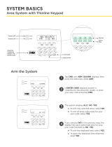
1.1 Terminals (J9)
Power Connection Terminals
Powerisprovidedfromthe12VDCauxiliaryoutputoftheburglarycontrolpanel.
OBSERVEPOLARITY(SeeFigure1)
1. Using18-22AWGwire,connectthe
communicator
terminal+12tothepositiveterminalonthe
control
panel auxiliary output
.
2. ConnectthecommunicatorterminalG(Ground)tothenegativeterminalonthecontrolpanelauxiliary
output.
Standby Battery
Duringapoweroutage,theCellComSLdrawspowerfromtheburglarycontrolpanel’sbackup
battery.TheCellComSLmustbeincludedinthestandbybatterycalculationsfortheburglary
control panel.
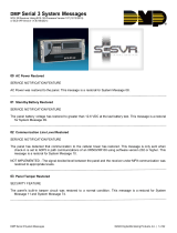
Zones 1-3
TerminalsZ1toZ3andG(Ground)providethreezonestoconnecttoindividualoutputsonthe
burglary control panel or to intrusion devices (PIR, door, panic buttons or windows contacts).
Figure 1: CellComSL Series Communicator
RESET
LOAD
BAT
MODEL CellComSL
PROG
S
N
+12 G Z1 Z2 Z4-Z4+GZ3 RTO2O1
RB
J8
J26
J9
S1
S2
S3
SYSTEM COMPONENTS
RESET
LOAD
BAT
MODEL CellComSL
PROG
S
N
+12
G Z1 Z2
Z4-Z4+
GZ3
RTO2O1
RB
J8
J26
J9
S1
S2
S3
Figure 2: Zones 1 - 3

Digital Monitoring Products
CellComSL
Series Communicator Install/Programming Guide
2
SYSTEM COMPONENTS
Zone 4
Zone4(Z4+andZ4-)isintendedforconnectiontothecontrolpanelbelloutput.Thiszonedetectsanalarm
condition on the burglary control panel by monitoring the voltage of the bell output. To enable alarm detection
operation,Zone4mustbeprogrammedasAUX2intheCellComSLprogramming.CellComSLSeriesCommunicator
mustperceivethecadenceforatleastfor3.5seconds.
ThetypeofCadencesenttotheCellComSLCommunicatorandthetypeofmessagetheCellComSLwillsendto
CentralStationarelistedbelow:
Cadence Type of Message
Steady Burglary
T3 CO
T4 Fire
Open-Collector Outputs
Thetwooutputs,terminalsO1andO2(seeFigure4),canbeprogrammedtoindicatethe
activityofthezonesorconditionsoccurringonthesystem.Open-Collectoroutputsdonot
provide a voltage but instead switch-to-ground voltage from another source. The outputs can
respond to any of the conditions listed below:
1) Activationbyzonecondition:Steady,Pulse,Momentary,orFollow
2) Communication
3) Armedareaannunciation
4) ExitandEntrytimers
5) SystemReady
6) LatetoClose
Dialer Connection
Usethetwomiddlewiresfromthetelephonecordconnectedtotheburglarycontrolpaneland
inserteachintoterminalR(Ring)andT(Tip)(SeeFigure5).CAUTION-Toreducetheriskof
re,useonlyNo.26AWGorlargertelecommunicationlinecord.
1.2 Battery Connection (BAT J26)
Installation Safety
Ground Yourself Before Handling the Communicator! To discharge static, touch any grounded metal, such
as the control panel enclosure, before touching the communicator.
System Battery
Ifthesystembatteryislow,ornotpluggedintotheBATbatteryconnector,alowbatteryconditionisindicatedby
the
communicator
.
PluginthesystembatteryintheBATconnector(J26).
DMPrecommendsreplacingthebatteryevery3yearsundernormaluse.
Usethefollowingstepstoreplacethesystembattery.
1. UnplugthebatteryBATconnector(J26)fromthecommunicator.
2. LoosenthetopPCBsnaps.
3. Leanthe
communicator
PCB forward and lift out from the bottom PCB snaps.
4. Remove and properly dispose of the used battery.
Caution:Riskofre,explosion,andburns.Donotdisassemble,heatabove212°F(100°C),orincinerate.
Properly dispose of used batteries.
5. Place the new battery into the housing base with the battery wires directed toward the bottom left corner.
SeeFigure6.
6. SetthePCBintothebottomsnapsandpressintothetopsnapstosecureinplace.
Top PCB Snaps
Bottom PCB Snaps
Battery
connector
3.7 VDC
800 mAH Lithium
Ion Battery
Figure 6: Replacement Battery Locations
RESET
LOAD
BAT
MODEL CellComSL
PROG
S
N
+12 G Z1 Z2
Z4-Z4+G
Z3 RTO2
O1
RB
J8
J26
J9
S1
S2
S3
Figure 3: Zone 4
RESET
LOAD
BAT
MODEL CellComSL
PROG
S
N
+12 G Z1 Z2 Z4-Z4+GZ3 RTO2O1
RB
J8
J26
J9
S1
S2
S3
Figure 4: Outputs 1 and 2
RESET
LOAD
BAT
MODEL CellComSL
PROG
S
N
+12 G Z1 Z2 Z4-Z4+GZ3 RTO2O1
RB
J8
J26
J9
S1
S2
S3
Figure 5: Terminals T and R
RESET
LOAD
BAT
MODEL CellComSL
PROG
S
N
+12 G Z1 Z2
Z4-Z4+
GZ3
RTO2O1
RB
J8
J26
J9
S1
S2
S3

SYSTEM COMPONENTS
CellComSL
Series Communicator Install/Programming Guide Digital Monitoring Products
3
7. Plug the battery into the
BAT
connector(J26).
Note:Ifremovingthecommunicatorfromservice,disconnectthesystembatteryfromtheBATconnector(J26).
Battery Supervision
ThecommunicatorteststhebatteryonceeveryhourwhenDCpowerispresent.Thistestoccurs15minutespast
eachhourandlastsforveseconds.Aloadisplacedonthebatteryandifthebatteryvoltageislow,alowbattery
isdetected.IfDCpowerhasfailed,alowbatteryisdetectedanytimethebatteryvoltagefallsbelow3.7VDC.
1.3 Programming Connection (PROG J8)
A4-pinheader(PROG)isprovidedtoconnectakeypadwhenusingaDMPModel330
ProgrammingCable.Thisprovidesaquickandeasyconnectionforprogrammingthe
CellComSL
SeriesCellularAlarmCommunicator.Afterprogrammingiscomplete,remove
thekeypad.
1.4 Tamper (C3)
ThetamperbuttonispressedwhenthecoveroftheCellComSLSeries
Communicatorissecuredontotheenclosure.Whenthecoverisremoved,the
communicatorsendsaTamperTroublemessagetotheCentralStation.
1.5 Reset Button
TheResetbutton(S1)islocatedontherightsideofthecircuitboardandisused
toresetthecommunicatormicroprocessor.Afterresettingthe
communicator,
begin
programmingwithin30minutes.Ifyouwaitlongerthan30minutes,resetthe
communicator
again.
1.6 Load Button
The
CellComSL
SeriesCellularAlarmCommunicatorsoftwarecanbeupdated
viatheprogramming(PROG)header.Toupdatethecommunicatorwithanewsoftware
version, complete the following steps at the protected premise:
1. ConnectaDMP399CablefromtheProgrammingHeadertotheserialportofyour
PCoperatingRemoteLinkandcontainingthecommunicatorRUle.
2. StartRemoteLinkandcreateoropentheaccountthatmatchesthecommunicator
to be updated.
3. SettheConnectionInformationTypetoDirectwithabaudrateof38400and
choosetheappropriateCOMport.
4. SelectPanel>RemoteUpdate,thenselectthecorrectRUleforthe
communicator.
5. PressandholdtheLOADbutton(S2),thenpressandreleasetheRESETbutton.
6. ReleasetheLOADbuttonandclick<Update>inRemoteLink.
7. Afterthesoftwareupdateiscompleted,removethe399cableandpresstheRESETbuttontoresumenormal
operation.
Figure 5: Terminals T and R
RESET
LOAD
BAT
MODEL CellComSL
PROG
S
N
+12 G Z1 Z2 Z4-Z4+GZ3 RTO2O1
RB
J8
J26
J9
S1
S2
S3
Figure 7: PROG Port Location
RESET
LOAD
BAT
MODEL CellComSL
PROG
S
N
+12
G Z1 Z2 Z4-Z4+GZ3 RTO2O1
R
B
J8
J26
J9
S1
S2
S3
Figure 8: Tamper (S3) Location
RESET
LOAD
BAT
MODEL CellComSL
PROG
S
N
+12 G Z1 Z2 Z4-Z4+GZ3 RTO2O1
RB
J8
J26
J9
S1
S2
S3
Figure 9: Reset (S1) and
Load (S2) Button Location

Digital Monitoring Products
CellComSL
Series Communicator Install/Programming Guide
4
INSTALLATION
Mounting the CellComSL Series Communicator
2.1 Selecting a Location
Install the communicator away from metal objects. DO NOTmounttheCellComSLSeriesCommunicatorinsideor
ontheburglarycontrolpanelmetalenclosure(SeeFigure10).
Mountingthecommunicatoronornearmetalsurfacesimpairsperformance.Theenclosureforthe
c
ommunicator
mustbemountedusingtheprovided#6screwsinthefourmountingholes(SeeFigure11).Mounttheenclosurein
a secure, dry place away from metal objects to protect the communicator from damage due to tampering or the
elements. It is not necessary to remove the PCB when installing the enclosure.
Burglary Control
Panel
Metal Enclosure
Figure 11: Mounting Screw Locations
RESET
S1
LOAD
S2
BAT
MODEL CellComSL
PROG
S
N
+12 G Z1 Z2 Z4-Z4+GZ3 RTO2O1
RB
Mounting Screw Locations
Figure 10: Suggested Mounting Locations
Figure 12: Wire Routing
RESET
S1
LOAD
S2
BAT
MODEL CellComSL
PROG
S
N
+12 G Z1 Z2 Z4-Z4+GZ3 RTO2O1
RB
Wheninstallingcomponentwirescaremustbetakentorouteallwiresinsuchamannerthattheywillnot
interferewiththeTamperswitch.SeeFigure12.

CellComSL
Series Communicator Install/Programming Guide Digital Monitoring Products
5
APPLICATIONS
Applications
TheCellComSLSeriesCommunicatorisusedinonlyoneofthethreeapplications:
3.1
Dialer Connection
ConnectthetwomiddlewiresofthephonelinefromthecontrolpanelandconnecttotheCellComSLSeries
CellularCommunicatortocaptureContactIDmessagesfromtheburglarycontrolpanelandsendthemessagetoa
DMPModelSCS-1RorSCS-VRReceiver.OnlyOutputscanbeusedincombinationwiththisapplication(SeeFigure
13).
3.2 Zones 1 - 3 and Outputs
Wiredintrusiondevicessuchasdoorcontacts,tamperswitches,panicbuttonsandPIRscanbewiredtoZ1through
Z3forzonesensingsupervision.ConnectwiresfromtheCellComSLOutputs(O1andO2)totheburglarycontrol
panelzones.(See1.1Terminals>ZonesformoreinformationandFigure14forwiringdetails).
Use 18-22 AWG for
Power Supply connection
Z3 +
Z4 +
Z4 -
GND
OUT1
OUT2
CONTROL PANEL TIP
CONTROL PANEL RING
12 VDC Aux. Output +
-
Ground
Burglary Panel
The panel or separate power
supply must be 12 Volt Regulated
and Power Limited.
Telephone
Jack
Connector
Z1 +
Z2 +
BELL -
BELL +
Input Zone 2 +
Input Zone 2 -
Input Zone 1 +
Input Zone 1 -
RESET
S1
LOAD
S2
BAT
MODEL CellCom
PROG
S
N
+12 G Z1 Z2 Z4-Z4+GZ3 RTO2O1
RB
†
{
Normally Open
Common
Normally Closed
Normally Open
Common
Normally Closed
†
{
Normally Open
Common
Normally Closed
†
{
J8
J26
J9
S1
S2
S3
Figure 13: CellComSL Series Wiring Diagram for Tip and Ring Connection
Use 18-22 AWG for
Power Supply connection
Z3 +
Z4 +
Z4 -
GND
OUT1
OUT2
CONTROL PANEL TIP
CONTROL PANEL RING
12 VDC Aux. Output
+
-
Ground
Burglary Panel
The panel or separate power
supply must be 12 Volt Regulated
and Power Limited.
Telephone
Jack
Connector
Z1 +
Z2 +
BELL -
BELL +
Input Zone 2 +
Input Zone 2 -
Input Zone 1 +
Input Zone 1 -
RESET
S1
LOAD
S2
BAT
MODEL CellCom
PROG
S
N
+12 G Z1 Z2 Z4-Z4+GZ3 RTO2O1
RB
†
{
Normally Open
Common
Normally Closed
Normally Open
Common
Normally Closed
†
{
Normally Open
Common
Normally Closed
†
{
J8
J26
J9
S1
S2
S3
Wired Door
Contact
Figure 14: CellComSL Series Wiring Diagram for Zones 1 - 3 and Outputs.

Digital Monitoring Products
CellComSL
Series Communicator Install/Programming Guide
6
APPLICATIONS
3.3 Zone 4 and Outputs
Zone4(Z4+andZ4-)isintendedforconnectiontothecontrolpanelbelloutput.Thiszonedetectsanalarm
conditionontheburglarycontrolpanelbymonitoringthevoltageofthebelloutput.(See1.1Terminals>Zone4
for more information and Figure 15 for wiring details).
3.4 Virtual Keypad App
UsingyourSmartphoneandtheDMPVirtualKeypadApp,youcanconnecttoyourCellComSLSeriesCommunicator
toarmtheArea,congureZ-Wavedevices(CellComSLCZonly),congureyourFavorites(CellComSLCZonly),
congureRooms(CellComSLCZonly),turnOutputsonandoff,andadd,editorremoveUsers.
Use 18-22 AWG for
Power Supply connection
Z3 +
Z4 +
Z4 -
GND
OUT1
OUT2
CONTROL PANEL TIP
CONTROL PANEL RING
12 VDC Aux. Output +
-
Ground
Burglary Panel
The panel or separate power
supply must be 12 Volt Regulated
and Power Limited.
Telephone
Jack
Connector
Z1 +
Z2 +
BELL -
BELL +
Input Zone 2 +
Input Zone 2 -
Input Zone 1 +
Input Zone 1 -
RESET
S1
LOAD
S2
BAT
MODEL CellCom
PROG
S
N
+12 G Z1 Z2 Z4-Z4+GZ3 RTO2O1
RB
†
{
Normally Open
Common
Normally Closed
Normally Open
Common
Normally Closed
†
{
Normally Open
Common
Normally Closed
†
{
J8
J26
J9
S1
S2
S3
Figure 15: Zone 4 and Output Connections
Enter Email
Enter Password
Log In
Virtual Keypad
Figure 16: Virtual Keypad Application can be used to access the CellComSL Series Communicator.

CellComSL
Series Communicator Install/Programming Guide Digital Monitoring Products
7
Z-WAVE SETUP
Z-Wave Setup
(Model CellComSLCZ Only)
User Code Level: Master only.
(AccessedthroughtheUserMenutoprogramyourZ-WaveDevices,UserCodes,etc.)Yoursystemmayincludea
DMPZ-Wavecontroller.TheZ-WavecontrollerallowsshortrangeradiocontrolofZ-Wavedevicesthatyouoryour
installationcompanymayprovidesuchaslightingcontrolmodules,thermostatcontrols,anddoorlocks.Z-Wave
SetupallowsyoutoprogramthesystemtocontroltheZ-Wavedevices.YoumaycontrolyourZ-Wavedevices
fromyouriPhone/iPadorAndroiddeviceusingtheDMPVirtualKeypadApporfromyourkeypadbyactivatinga
FavoritefromtheFavoritesUserMenu.Theavailablesetupoptionsare:Add,List,Remove,Favorites,Transferand
Rediscover.
• SelectADDtoaddaZ-Wavedevicetoyoursystem.
• SelectLISTtodisplayalistofZ-Wavedevicesalreadyaddedandstoredinyoursystem.
• SelectREMOVEtocompletelyremoveaZ-Wavedevicefromyoursystem.
• SelectFAVtoAdd,EditorRemoveaFavorite.
• SelectXFERtotransferZ-Wavedeviceinformationfromanothermanufacturer’sportableZ-Wavecontroller
to your system.
• SelectREDISCtorequireyoursystemtorediscoverandconrmradiocommunicationwithalloftheadded
Z-Wavedevices.
5.1 Add Z-Wave Devices (ADD)
ThisoptionallowsyoutoADDaZ-Wavedevicetoyoursystem.Onceadded,aZ-Wavedevicemaybeassignedtoa
Favorite.
1. AccesstheUserMenu.
2. Press COMMANDuntilZWAVESETUP?displays.
3. PressanySelectkey.ThekeypaddisplaysADDLISTREMOVE.
4. SelectADD.PROCESSINGmaybrieydisplay.WhenPRESSBUTTONONDEVICETOADDdisplayspressthe
program button on the Z-Wavedevice.SeetheZ-Wavedevice’sdocumentationformoreinformation.
5. Whenthedeviceinformationisreceivedbythesystem,thekeypadbeepsonceanddisplaysDEVICEFOUND.
6. Onceadded,thekeypaddisplaysthetypeofdeviceandthedefaultdevicename.PressCOMMAND.
7. PressanytoprowSelectkeyandenteruptoa16charactercustomnameforthedevice.SeeEnteringNames
inAppendixD.
8. Press the COMMANDkeytostorethenewname.
Note:Amaximumof232Z-Wavedevicescanbeaddedtothesystem.Whenthemaximumnumberofdeviceshavebeen
added,thekeypaddisplaysZWAVETABLEFULLandnoadditionalZ-Wavedevicesmaybeaddedwithoutremoving
some existing devices.
5.2 List Z-Wave Devices (LIST)
ThisoptionallowsyoutoeditthenameofaZ-WavedeviceorconrmradiocommunicationwiththeZ-Wave
device.WhenLISTisselected,therstZ-Wavedevicestoredinthesystemisdisplayed.Remainingdevicescan
be viewed by pressing the COMMANDkey.Lightingcontrolmodules,aredisplayedrst,followedbydoorlocksand
then thermostat controls.
TheavailableLISToptionsare:RenameandStatus.
• SelectRENAMEtoenterupto16charactersforanewdevicename.
• SelectSTATUStoconrmradiocommunicationwiththeZ-Wavedevice.
5.3 RENAME Z-Wave Devices
1. AccesstheUserMenu.
2. Press COMMANDuntilZWAVESETUP?displays.
3. PressanySelectkey.ThekeypaddisplaysADDLISTREMOVE.
4. SelectLISTtodisplayDEVICELISTandtherstZ-Wavedevicestored.PresstheCOMMANDkeytoadvance
through the list of Z-Wavedevices.
5. PressanySelectkeytodisplayDEVICERENAMESTATUS.
6. SelectRENAMEandenterupto16charactersforanewdevicename.SeeEnteringNamesinAppendixD.
7. Press COMMANDtosavethenewZ-WavedevicenameandreturntotheDEVICELIST.

Digital Monitoring Products
CellComSL
Series Communicator Install/Programming Guide
8
Z-WAVE SETUP
5.4 STATUS of Z-Wave Devices
1. AccesstheUserMenu.
2. Press COMMANDuntilZWAVESETUP?displays.
3. PressanySelectkey.ThekeypaddisplaysADDLISTREMOVE.
4. SelectLISTtodisplayDEVICELISTandtherstZ-Wavedevicestored.PresstheCOMMANDkeytoadvance
through the list of Z-Wavedevices.
5. PressanySelectkeytodisplayDEVICERENAMESTATUS.
6. SelectSTATUStoconrmradiocommunicationwiththeZ-Wavedevice.
7. ThedevicenameandOKAYdisplayswhenthedevicestoredinthesystemcommunicates.
8. Press the COMMANDkeytoreturntothedevicelistanddisplaythenextdeviceinthelist.
9. Ifthedevicestoredinthesystemdoesnotcommunicate,thedevicenameandFAILEDdisplays.Pressthe
COMMANDkeyandREMOVEFAILEDDEVICEdisplays.
10. SelectYEStoremovethefaileddevicefromthesystemmemory.SelectNOtoleavethedeviceinthesystem
memory and to return to the device list.
11. Whenthedevicehasbeenremoved,thedevicenameandREMOVEDisdisplayedandthesystemnolongertries
to communicate with the Z-Wavedevice.
5.5 Remove Z-Wave Devices (REMOVE)
EachZ-Wavedeviceaddedtoyoursystemremainsinyoursystemunlessitisremoved.Thisoptionallowsyouto
remove Z-Wavedevicesfromyoursystem.
1. AccesstheUserMenu.
2. Press COMMANDuntilZWAVESETUP?displays.
3. PressanySelectkey.ThekeypaddisplaysADDLISTREMOVE.
4. SelectREMOVE.PROCESSINGmaybrieydisplay.WhenPRESSBUTTONONDEVICETOREMOVEdisplayspress
the program button on the Z-Wavedevice,thedevicenameandREMOVEDisdisplayedtoindicatetheZ-Wave
device has been removed.
5.6 Favorites (FAV)
Z-WavedevicescanbegroupedtogethertocreateaFavorite.Thisoptionallowsyoutoprogramupto20Favorites
inyoursystemandthenADD,EDITORREMOVEupto25Z-WavedevicesinaFavorite.Whenactivatedfromthe
FAVORITEusermenu,acommandissenttoitsZ-WaveDevices.AFavoritecanonlybeactivated,orturnedon.
AseparateFavoritemustbecreatedtochangetheconditionssetbytherstFavorite.Forexample,aFavorite
called“MovieNight”couldlocktheexteriordoors,closethegaragedoor,adjustthetemperature,anddimthe
lightsinthefamilyroomtothedesiredlevel.AnotherFavoritecalled“Wakeup”couldthenturnonthelights,
adjustthetemperature,unlocktheexteriordoors,andraisethegaragedoors.
5.7 Adding a FAVORITE
1. AccesstheUserMenu.
2. Press COMMANDuntilZWAVESETUP?displays.
3. PressanySelectkey.ThekeypaddisplaysADDLISTREMOVE.
4. Press COMMANDagaintodisplayFAVXFERREDISC.SelectFAVandFAVORITENUMBER:-isdisplayed.
5. EnteraFavoritenumberbetween1and20andpressCOMMAND.IftheFavorite number entered is unassigned,
*UNUSED*displays.IftheFavoriteisalreadyassigned,youmaychangethenameorpressthebackarrowand
enter a new number.
6. PressanySelectkeyandacursordisplays.EnteraFavorite name up to 16 characters. To remove a Favorite,
press Command without entering a name.
7. Press COMMANDtosavetheFavorite and the FavoritenameandADDEDITREMOVEdisplays.
5.8 ADD Devices to FAVORITES
1. AccesstheUserMenu.
2. Press COMMANDuntilZWAVESETUP?displays.
3. PressanySelectkey.ThekeypaddisplaysADDLISTREMOVE.
4. Press COMMANDagaintodisplayFAVXFERREDISC.SelectFAVandFAVORITENUMBER:-isdisplayed.
5. EnteraFavoritenumberbetween1and20andpressCOMMAND.
6. The Favorite number and name displays. Press COMMANDandtheFavoriteNameandADDEDITREMOVE
displays.

CellComSL
Series Communicator Install/Programming Guide Digital Monitoring Products
9
Z-WAVE SETUP
7. SelectADDandtherstZ-WavedevicestoredinthesystemthathasnotalreadybeenaddedtothisFavorite is
displayed. Remaining devices can be viewed by pressing the COMMANDkey.
8. PressanySelectkeytoassignthedisplayeddevicetotheFavorite. The device name and the current device
settingsdisplay.WhenaddedtoaFavorite,aZ-WavedevicecanbeprogrammedtorespondtovariousON/
OFF/LOCK/UNLOCK/HEAT/COOLcommandsbasedonyourdesiredsettings.Tochangeadevicesetting,See
DeviceSettingsinFavorites.
5.9 Device Settings in FAVORITES
Lights
1. PressanySelectkeyatSETTING:andONOFFDIMdisplays.PresstheSelectkeyunderthedesiredsetting.
2. ForONorOFFsetting,whenselected,theFavorite name and the next Z-Wavedevicestoredinthesystem
displays.
3. ForDIMsetting,DIMLEVEL:withthecurrentsettingdisplays.Tochangethesetting,pressanySelectkeyand
enterthenewlevel(1-10)andPressCOMMAND.
4. The Favorite name and the next Z-Wavedevicestoredinthesystemdisplays.
Locks
1. PressanySelectkeyatSETTING:andLOCKUNLOCKdisplays.To changethesetting,presstheSelect
keyunderthenewsetting.
2. The Favorite name and the next Z-Wavedevicestoredinthesystemdisplays.
Thermostats
1. PressanySelectkeyatSYSTEM:andOFFCLHTdisplays.TochangethesettingofOFF,COOLorHEAT,press
theSelectkeyunderthenewsetting.
2. SelectOFFtodisplayFANSETTING:.
3. PressanySelectkeyandONAUTOdisplays.PresstheSelectkeyunderthedesirednewsettingtochange.
4. SelectCLtodisplayCOOL.
5. Tochangethesetting,pressanySelectkey,enterthenewtemperatureandpressCOMMAND.
6. PressanySelectkeyandthekeypaddisplays
FANSETTING:.
7. PressanySelectkeyandONAUTOdisplays.PresstheSelectkeyunderthedesirednewsettingtochange.
8. SelectHTtodisplayHEAT.
9. Tochangethesetting,pressanySelectkeyandenterthenewtemperatureandPressCOMMAND.
10. PressanySelectkeyandthekeypaddisplays
FANSETTING:.
11. PressanySelectkeyandONAUTOdisplays.PresstheSelectkeyunderthedesirednewsettingtochange.
12. The Favorite name and the next Z-Wavedevicestoredinthesystemdisplays.
Note:Amaximumof25devicescanbeassignedtoeachFavorite.Whenattemptingtoaddadeviceandthe
maximumnumberofdeviceshasbeenassigned,FAVORITEFULLisdisplayed.NoadditionalZ-Wavedevices
may be added to this Favorite, however a new Favorite may be created and devices added to the new
Favorite.
5.10 EDIT Devices in FAVORITES
1. AccesstheUserMenu.
2. Press COMMANDuntilZWAVESETUP?displays.
3. PressanySelectkey.ThekeypaddisplaysADDLISTREMOVE.
4. Press COMMANDagaintodisplayFAVXFERREDISC.SelectFAVandFAVORITENUMBER:-isdisplayed.
5. EnteraFavoritenumberbetween1and20andpressCOMMAND.
6. The Favorite number and name displays. Press COMMANDandtheFavoriteNameandADDEDITREMOVE
displays.
7. SelectEDITandtherstZ-WavedevicestoredintheFavorite displays. Remaining devices can be viewed by
pressing the COMMANDkey.
Note: Z-Wavedevicesaredisplayedbydevicetype;Lightsrst,followedLocks,andThermostatslast.Bypressing
the COMMANDkeyyoucanscrollthroughthedevicesassignedtotheselectedFavorite.
8. PressanySelectkeytodisplaythedevicenameandthesettingforthedevice.
9. Tochangethesetting,SeeDeviceSettingsinFavorites.
10. Oncethedevicesettingshavebeenentered,theFavorite name and the next Z-Wavedevicestoredinthe
selected Favorite displays.

Digital Monitoring Products
CellComSL
Series Communicator Install/Programming Guide
10
Z-WAVE SETUP
5.11 REMOVE Devices from FAVORITES
1. AccesstheUserMenu.
2. Press COMMANDuntilZWAVESETUP?displays.
3. PressanySelectkey.ThekeypaddisplaysADDLISTREMOVE.
4. Press COMMANDagaintodisplayFAVXFERREDISC.SelectFAVandFAVORITENUMBER:-isdisplayed.
5. EnteraFavoritenumberbetween1and20,pressCOMMAND.
6. The Favorite number and name displays. Press COMMANDandtheFavoriteNameandADDEDITREMOVE
displays.
7. SelectREMOVEandtherstZ-WavedevicestoredintheFavorite displays. Remaining devices can be viewed
by pressing the COMMANDkey.
8. PressanySelectkeytoremovethedevicefromtheFavorite.REMOVEDEVICEFROMFAV?NOYESdisplays.
WhenYESisselected,thedeviceisremovedfromtheFavorite.
5.12 Transfer Controller (XFER)
This option allows the transfer of all existing Z-Wavedevicesthatarecurrentlyprogrammedinanother
manufacturer’sZ-Waveportablecontrollertoyoursystem.
This operation will overwrite all Z-Wavedevicesthatareprogrammedinyoursystem.Thisoptiontypically
occursatthetimeyourDMPZ-Wavecontrollerisinstalled.
Initiatethetransferattheothermanufacturer’sZ-Waveportablecontrollerafterstartingthetransfer
ontheDMPkeypad.Z-WavedevicesareNOToverwrittenuntilthetransferhasbeeninitiatedattheother
manufacturer’sZ-Waveportablecontroller.Thetransfershouldnotbestoppedoncetheprocesshasbeeninitiated
fromtheothermanufacturer’sZ-Waveportablecontroller.
Transfer Operation:
1. AccesstheUserMenu.
2. Press COMMANDuntilZWAVESETUP?displays.
3. PressanySelectkey.Thekeypaddisplays
ADDLISTREMOVE.
4. Press COMMANDagaintodisplayFAVXFERREDISC.SelectXFER.ThekeypaddisplaysXFERWILLDELETE
EXISTINGDEVICESthendisplaysXFERCNTRLSURE?YESNO.
5. SelectYEStotoallowreceiptofZ-Wavedevicestoyoursystem.ThekeypaddisplaysTRANSFERRINGZ-WAVE
DEVICES.PressingtheBackArrowkeycancelsthetransfer.SelectNOtoexittheXFERmenuandreturnto
ZWAVESETUP?.AllprogrammingwillstillbeintactontheDMPZ-Wavecontrollerandwillcancelthetransfer.
6. Initiate the transfer at the othermanufacturer’sZ-Waveportablecontroller.AllZ-Wavedevicesareadded
tothesystemwithadefaultname(devicetypeandnumber).A16-characternamemaybeassignedtothe
Z-Wavedevicesafterthetransferiscomplete.WhenthetransferiscompletethescreenwilldisplayZWAVE
SETUP?.
Note:IfTRANSMISSIONFAILEDdisplaysonthescreen,yoursystemmemoryisclearedofallpriorZ-Wavedevices
programmingandwillneedtoaddeachZ-Wavedeviceindividually.
5.13 Rediscover (REDISC)
This option allows your system to search for and re-establish communication with Z-Wavedevicesthatmayhave
failedtocommunicate.OnlyZ-Wavedevicesalreadyprogrammedintoyoursystemareincludedintherediscovery
search.AnyprogrammedZ-Wavedevicethatisnotfoundduringrediscoverywillbedeletedfromyoursystem.
1. AccesstheUserMenu.
2. Press COMMANDuntilZWAVESETUP?displays.
3. PressanySelectkey.ThekeypaddisplaysADDLISTREMOVE.
4. Press COMMANDagaintodisplayFAVXFERREDISC.
5. SelectREDISC,thekeypaddisplaysREDISCOVERINGZWAVEDEVICESwhilethesystemissearchingforZ-Wave
devices.
6. Whentherediscoveryiscomplete,thekeypadreturnstoZWAVESETUP?

PROGRAMMING INTRODUCTION
CellComSL
Series Communicator Install/Programming Guide Digital Monitoring Products
11
Programming the
CellComSL
Series Cellular Alarm Communicator
6.1 Before You Begin
Before starting to program, we recommend you read through the contents of this manual. The information in
thisdocumentallowsyoutoquicklylearntheprogrammingoptionsandoperationalcapabilitiesofthe
CellComSL
SeriesCellularAlarmCommunicator.
AfterthisIntroduction,theremainingsectionsdescribethefunctionsofeachprogrammingmenuitemsalongwith
their available options. The
communicator
contains all of its programming information in an on-board processor
and does not require an external programmer.
In addition to this manual, you should also be familiar with the following
documents:
• CellComSL
SeriesCellularAlarmCommunicatorUserSheet
• CellComSL
SeriesCellularAlarmCommunicatorProgrammingSheet
Programming Information Sheet
Included with each communicatoraretheProgrammingSheets.Thesesheetslistthevariousoptionsavailablefor
programming the
communicator
.Beforestarting,completelylloutthesheetswiththeprogrammingoptionsyou
intend to enter into the
communicator
.
Having completed programming sheets available while entering data helps to prevent errors and can shorten
the length of time you spend programming. Completed sheets also provide you with an accurate account of the
communicator
’sprogramyoucankeeponleforfuturesystemserviceorexpansion.
The remainder of the Introduction explains starting and ending a programming session.
6.2 Getting Started
Ground Yourself Before Handling the Panel! Touch any grounded metal before touching the communicator
to discharge static.
Remove All Power From the Panel! RemoveallACandBatterypowerfromthecommunicator before
installing or connecting any wires to the communicator.
The communicatorshouldbecompletelyinstalledbeforeyoubeginprogramming.Makesurethecommunicator is
properlygrounded,andtheACandbatterywiresarecorrectlyinstalled.
Initializing the
CellComSL
Series
Whenprogramminga
communicator
forthersttimeorrewritingtheentireprogramofanexistingcommunicator,
use the Initialization functiondescribedinsection7.Initializingclearsthecommunicator’smemoryofanyold
dataandsetsthehighestnumberedusernumbertousercode99.
Accessing the Programmer
To access the programmer function of the
communicator
:
1. ConnectthekeypadtothePROGheader
2. Press the reset button.
3. Enterthecode6653(PROG).
4. Thekeypaddisplays:PROGRAMMER.
6.3 Programming Menu
Youarenowreadytostartprogrammingthe
CellComSL
SeriesCellularAlarmCommunicator.Pressingthe
COMMANDkeyscrollsyouthroughtheprogrammingmenuitemslistedbelow.
Menu Item Section in This Manual Menu Item Section in This Manual
Initialization 7 Output Options 13
Communication 8 Area Information 14
Messaging Setup 9 Zone Information 15
Remote Options 10
Stop
16
System Reports 11 Set Lockout Code 17
System Options 12
Toselectasectionforprogramming,pressanySelectkey/areawhenthenameofthatsectiondisplaysonthe
keypad.Thedetailedinstructionsforeachprogrammingsteparefoundinthismanual.

Digital Monitoring Products
CellComSL
Series Communicator Install/Programming Guide
12
PROGRAMMING INTRODUCTION
6.4 Reset Timeout
The
CellComSL
SeriesCellularAlarmCommunicatorhasafeaturethatrequiresyoutoentertheProgrammerwithin
30minutesofresettingthecommunicator.After30minutes,ifyouattempttoprogrambyenteringthe6653
(PROG)code,thekeypaddisplays:RESET PANEL.Youmustresetthe
communicator
and enter the program code
withinthenext30minutes.
IfyouarealreadyintheProgrammeranddonotpressanykeysontheprogrammingkeypadfor30minutes,the
communicator
terminatesprogramming.Alldataentereduptothatpointissavedinthecommunicatormemory.
Using the STOP function disarms all areas:Toexitthecommunicator’sProgrammeryoumustusetheSTOP
function. The STOP optionisthesecondtothelastoptioninprogramming.TheStopfunctiondisarmsall
areasandclearsthecommunicator’sStatusList.
TheprogrammingsessionisthenterminatedandthekeypadreturnstotheStatusListorMainScreen.
6.5 Special Keys
Thefollowingspecialkeys/areasarecommontoallDMPkeypads.
COMMAND (CMD) Key
PressingtheCOMMANDkeyallowsyoutogoforwardthroughtheprogrammingmenuandthrougheachstepofa
programmingsection.Asyougothroughtheprogramming,thekeypaddisplayshowsanycurrentprogramming
alreadystoredinthecommunicatormemory.Ifnochangeisrequiredforaprompt,presstheCOMMANDkeyto
advance to the next step.
TheCOMMANDkeyisalsousedtoenterinformationintothecommunicator’smemorysuchasphonenumbersor
zonenames.PresstheCOMMANDkeyafterenteringinformation.
Back Arrow (<—) Key
UsetheBackArrowkeytobackuponestepwhileprogramming.TheBackArrowkeyisalsousedwhenanerroris
madewhileenteringinformation.PresstheBackArrowkeyoncetoerasethelastcharacterentered.
Select Keys/Areas
ThetoprowofkeysarecalledtheSelectkeysonThinline,andAqualitekeypadsorSelectAreasonGraphic
Touchscreenkeypads.EachtimeyouneedtopressaSelectkey,thekeypaddisplaysthefunctionoroptionsabove
oneofthekeysorintheSelectArea.DisplayingchoicesaboveindividualSelectkeysorinSelectAreasallows
themtobeusedformanydifferentapplications.Forexample,youcanenterAMorPMwhenprogrammingthe
automatic test time or answer YES or NO for a system option.
Duringprogramming,theSelectkeys/areasalsoallowyoutochangeinformationcurrentlyincommunicator
memorybypressingtheappropriateSelectkeyunderoronthedisplay.Youthenenterthenewinformationusing
thekeypaddataentrydigitkeys.
Whentherearemorethanfourresponseoptionsavailable,presstheCOMMANDkeytodisplaythenextonetofour
options.PressingtheBackArrowkeyallowsyoutoreviewthepreviousfourchoices.
TheSelectkeys/areasarealsousedforchoosingasectionfromtheprogrammingmenu.PressanySelectkeyor
touchtheSelectAreawhentheprogrammingsectionnameyouwantdisplays.
On Thinline and Aqualite keypads,wheninstructedtopresstherstSelectkey,pressthefarleftSelectkey;the
secondSelectkeyisthesecondfromtheleft;thirdSelectkeyissecondfromtheright;andthefourthSelectkey
isthefarrightkey.SeeFigure17.
On Graphic Touchscreen Keypads,wheninstructedtopresstherstSelectkey,touchSelectArea1;thesecond
SelectkeytouchSelectArea2;thirdSelectkeytouchSelectArea3;andthefourthSelectkeytouchSelectArea4.
SeeFigure18.
6.6 Entering Alpha Characters
Someoptionsduringprogrammingrequireyoutoenteralphacharacters.Toenteranalphacharacter,pressor
touchthekeythathasthatletterwrittenbelowit.Thekeypaddisplaysthenumberdigitofthekey.Next,press
theSelectkey/areathatcorrespondstothelocationoftheletterunderthekey.PressingadifferentSelectkey/
areachangestheletter.Whenanotherdigitkeyispressed,thelastletterdisplayedisretainedandtheprocess
starts over.
Figure 17: Thinline/Aqualite Select Keys Figure 18: Graphic Touchscreen Select Areas
First Letter
Second Letter
Third Letter
Special Character
(CBA
32-Character Display
Select Area 1
Select Area 2
Select Area 3
Select Area 4

CellComSL
Series Communicator Install/Programming Guide Digital Monitoring Products
13
PROGRAMMING INTRODUCTION
6.7 Entering Non-Alpha Characters
Toenteraspaceinanalphaentry,pressthe9digitkeyfollowedbythethirdSelectkey/area.Thethree
charactersonthe9digitkeyareY,Z,andspace.Youcanalsoenterthefollowingcharacters:–(dash),.(period),*
(asterisk),and#(poundsign)usingthe0(zero)keyandthefourSelectkeys/areasfromlefttoright.Forexample,
toentera–(dash),pressthe0(zero)keyandthentheleftSelectkey/area.Adashnowappearsinthekeypad
display.ThetablebelowshowsthecharacterlocationsforDMPkeypads.
Key Number Select Key 1 Select Key 2 Select Key 3 Select Key 4
1 A B C (
2 D E F )
3 G H I !
4 J K L ?
5 M N O /
6 P
Q
R &
7 S T U @
8 V W X ,
9 Y Z space _
0 - . * #
6.8 Keypad Displays Current Programming
Eachprogrammingpromptdisplayedatthekeypadshowsthecurrentlyselectedoptioninthecommunicator
memory.Theseoptionsareeithershownasanumber,ablank,oraNO or YES.Tochangeanumberorblanktoa
newnumber,pressanytoprowSelectkeyortouchanySelectArea.Thecurrentoptionisreplacedwithadash.
Pressthenumber(s)onthekeypadyouwanttoenterasthenewnumberforthatprompt.Itisnotnecessaryto
enternumberswithleadingzeros.Thecommunicatorautomaticallyrightjustiesthenumberwhenyoupressthe
COMMANDkey.
To change a programming prompt that requires a NO or YESresponse,presstheSelectkeyortouchtheSelect
Areafortheresponsenotselected.SeeFigure19.
For example, if the current prompt is selected as YES and you want to change it to NO,onThinlineorAqualite
keypadspressthethirdtoprowSelectkey.OnGraphicTouchscreenkeypadstouchSelectArea3.Thedisplay
changes to NO.PresstheCOMMANDkeytodisplaythenextprompt.
THEN
Press the black colored top
row Select key/area.
The keypad displays the new
selection. Press CMD to advance.
YESBELL TST
NOBELL TST
YESBELL TST
NOBELL TST
Thinline,
Aqualite,
Wireless
Keypads
Clear Touch
or Graphic
Keypads
Figure 19: Changing the Current Programming Option

Digital Monitoring Products
CellComSL
Series Communicator Install/Programming Guide
14
INITIALIZATION
Initialization
7.1 Initialization
This function allows you to set the communicator’sprogrammedmemorybacktothe
factory defaults in preparation for system programming.
AfteryouselectYEStoclearasectionofmemory,thecommunicatorasksifyouaresure
you want to clear the memory. This is a safeguard against accidently erasing part of your
programming.NomemoryisclearedfromtheprogramminguntilyouanswerYEStothe
SURE?YES NOprompt.
7.2 Clear All Codes
NOleavesexistingcodesintact.
YESclearstheusercodememoryandassignstheusercodenumber99touser20.
7.3 Clear All Schedules
NO -Leavesexistingschedulesintact.
YES - Clears all schedules from the programming.
7.4 Clear Events
NO leaves existing event memory intact.
YES clears all event memory currently held in the communicator’sDisplayEventsbuffer.
7.5 Clear Zone Programming
NO leaves existing zone information intact.
YES setsallzonesinthesystemto*UNUSED*
7.6 Clear Communication
NO - Leavesexistingcommunicationprogrammingintact.
YES - Clears communication to factory defaults.
7.7 Set to Factory Defaults
NO leaves the remainder of the existing communicator programming intact.
YES sets the communicatorprogrammingbacktofactorydefaultselectionsandclears
allZ-WavedeviceprogrammingandFavoritesfromthecommunicator.SelectingYES
does not clear the event memory, zone, user code information, or schedules.
INITIALIZATION
CODES? NO YES
SURE? YES NO
SCHEDS? NO YES
SURE? YES NO
EVENTS? NO YES
SURE? YES NO
ZONES? NO YES
SURE? YES NO
COMMS? NO YES
SURE? YES NO
DEFAULTS? NO YES
SURE? YES NO
CODES?
NO YES
SCHEDS? NO YES
For each section of the panel program you can
initialize, a NO or YES option is provided.
Selecting YES advances you to
a confirmation prompt.
If you select YES, the panel initializes that section of
the program and advances you to the next prompt.
If you select NO, the panel advances you to the next
section prompt but does not initialize that section of
the program.
SURE? YES NO
Selecting NO
advances you to
the next prompt.
/