
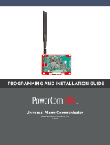
CellCom™LTE-V Series Communicator
Digital Monitoring Products, Inc.
© 2020
PROGRAMMING AND INSTALLATION GUIDE

TABLE OF CONTENTS
About the Communicator ......................1
System Components ............................... 1
Terminals.......................................................................1
Programming (PROG) Connection ....................2
Tamper...........................................................................2
Reset Button ...............................................................2
Load Button ................................................................2
Backlit Logo ................................................................3
ECP and DSC Passthru ............................................3
Installation ...............................................4
Select a Location .......................................................4
Mount the Communicator ......................................4
Wire the Communicator .........................................5
Connect the Antenna ..............................................5
Applications ............................................. 6
CID Dialer Connection .............................................6
Communication Failure (CellComF only) ........6
Zones 1‑4 Input Connection ..................................6
Zone4 Bell Connection ..........................................7
ECP Passthru Connection ......................................9
DSC Passthru Connection ......................................11
Arming and Disarming ...........................12
Use the Virtual Keypad App .................................12
Use Outputs ................................................................12
Activate the Cellular Module .................14
Dealer Admin Activation ........................................14
Tech APP Activation ................................................14
Remote Link Activation ..........................................14
Programming ...........................................15
Before You Begin ......................................................15
Getting Started ..........................................................15
Programming Menu ..................................................15
Reset Timeout ............................................................16
Special Keys ................................................................16
Letters and Special Characters............................17
Current Programming .............................................17
Initialization .............................................18
Clear All Codes ..........................................................18
Clear All Schedules ...................................................18
Clear Events ................................................................18
Clear Zone Programming .......................................18
Clear Communication ..............................................18
Set to Factory Defaults ...........................................18
Communication .......................................19
Account Number .......................................................19
Transmission Delay ...................................................19
Communication Type ..............................................19
Test Time ......................................................................19
Cell Test Days ..............................................................19
Check‑In Minutes .......................................................19
Fail Time Minutes ......................................................19
Receiver1 Programming .........................................19
Receiver2 Programming ........................................20
Remote Options ......................................21
Remote Key .................................................................21
Remote Disarm ..........................................................21
System Reports .......................................21
Opening/Closing Reports ......................................21
Zone Restoral Reports ............................................21
System Options .......................................22
Entry Delay 1 ...............................................................22
Exit Delay .....................................................................22
Cross Zone Time ........................................................22
Power Fail Delay ........................................................22
Swinger Bypass Trips ..............................................22
Reset Swinger Bypass .............................................22
Time Changes .............................................................23
Hours from GMT ........................................................23
Keypad Input ..............................................................23
CID Format ..................................................................23

Output Options .......................................24
Cutoff Outputs ...........................................................24
Output Cutoff Time ..................................................24
Communication Failure Output ...........................24
Armed Output ............................................................24
Remote Arming Output ..........................................24
Area Information .....................................25
Area Number ..............................................................25
Area Name ...................................................................25
Automatic Arming ....................................................25
Automatic Disarming ...............................................25
Zone Information ....................................26
Zone Number ..............................................................26
Zone Name ..................................................................26
Zone Type ....................................................................26
Next Zone .....................................................................27
Alarm Action ...............................................................27
Disarmed Open ..........................................................27
Message To Transmit................................................27
Output Number .........................................................27
Output Action.............................................................28
Swinger Bypass .........................................................28
Cross Zone ...................................................................28
Receiver Routing .......................................................28
Zone Number ..............................................................28
Stop ...........................................................29
Set Lockout Code ...................................29
Stop ................................................................................29
Set Lockout Code .....................................................29
Appendix ..................................................30
ECP Passthru .............................................................30
DSC Passthru ..............................................................30
False Alarm Reduction ............................................30
Diagnostics Function ...............................................31
Using the 984 Command Function ....................32
CELL ...............................................................................32
Using the Walk Test ..................................................32
Walk Test ......................................................................32
Trip Counter for Walk Test (STD) ........................32
Test End Warning ......................................................32
Failed Zones Display ................................................32
Cross Zoning ...............................................................32
Arming/Disarming Ademco Vista Panels ........33
FCC NOTICE .............................................36
Industry Canada ......................................36
NFPA 72 ...................................................36


CellCom‑LTE
Programming and Installation Guide Digital Monitoring Products
1
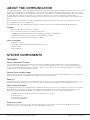
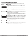
ABOUT THE COMMUNICATOR
The CellCom‑LTE Series Universal Alarm Communicator provides a fully supervised alarm communication path for any
burglary, commercial fire, or residential fire control panel. The CellCom‑LTE Series can be connected to any control
panel’s dialer output and used to capture Contact ID messages based on SIA DC‑05‑1999.09‑DCS. The communicator
also provides four input zones and two open‑collector outputs for connection to burglary, commercial fire, or
residential fire control panel outputs and zones. Zone4 allows a connection to the bell output of an existing control
panel.
The communicator operates in a variety of applications: CID Dialer Connection, Zones 1‑4 Input Connections, or
Zone4 Bell Connection. See Applications.
The CellComF‑LTE‑V Fire Alarm Communicator includes a red enclosure and a Model685‑R (Red) Backbox.
Features
• Can be powered from 12VDC or 24VDC
• Zone1‑4 terminals with 12V and 24V power input
• Tip & Ring terminal (CellCom‑LTE); Two Tip & Ring terminals (CellComF‑LTE)
• Programming header for connecting to a programming keypad
• LED to indicate armed state and power conditions
What is Included
• PCB with enclosure
• Model685
‑
R Back Box (CellComF‑LTE‑V modules only)
• Hardware pack
• External antenna
SYSTEM COMPONENTS
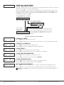
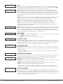
Terminals
Power Connection Terminals
The communicator may be powered from the 12VDC or 24VDC auxiliary output of the control panel. Observe
polarity and use 18‑22 AWG wire to connect the
communicator
terminal +12 to the +12 or +24V positive terminal
on the
control panel auxiliary output
. See Figure 1. Connect the communicator terminal G(ground) to the negative
terminal on the control panel auxiliary output.
Control Panel Standby Power
During a power outage, the communicator draws power from the control panel’s backup battery. The communicator
must be included in the standby battery calculations for the control panel.
Zones 1‑4
Terminals Z1 to Z3, G(ground), Z4+ and Z4‑ provide four zones to connect to individual relay outputs on the control
panel. Zone4 (Z4+ and Z4‑) can be connected to the control panel bell output. See Zone4 Bell Connection.
Open‑Collector Outputs
Terminals O1 and O2 can be programmed to indicate the activity of the zones or conditions occurring on the system.
Open‑Collector outputs do not provide a voltage but instead switch‑to‑ground the voltage from another source.
Maximum voltage is 30VDC at 50mA. The outputs can respond to any of the conditions listed below:
• Activation by zone condition: Steady, Pulse, Momentary, or Follow
• Communication
• Armed area annunciation
• Remote Arming Output
Dialer Connection
Directly connect the Telco phone line (tip and ring) from the control panel to the terminalR(Ring) and one into
terminalT(Tip). For more information, refer to “CID Dialer Connection”.

Digital Monitoring Products
CellCom‑LTE
Programming and Installation Guide
2
Programming (PROG) Connection
A 4‑pin programming header is provided to connect a keypad when using a DMP Model330 programming cable.
This provides a quick and easy connection for programming the communicator. For 24VDC applications using the
communicator, connect the keypad using a Model330‑24 4‑wire programming harness with an in‑line resistor. After
programming is complete, remove the keypad.
Caution: If connecting to a 24VDC control panel, do not connect a keypad using a Model330 harness.
Tamper
The tamper is pressed when the cover of the communicator is secured onto the enclosure. When the cover is
removed, the communicator sends a tamper trouble message to the central station.
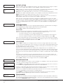
Reset Button
The reset button is located on the upper right side of the circuit board and is used to reset the communicator. After
resetting the communicator, begin programming within 30minutes. If you wait longer than 30minutes, reset the
communicator again.
Note: After the panel is reset, cell suppression is disabled for 30 minutes.
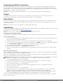
Load Button
Firmware can be updated with the programming header. Firmware updates are available for download, free of charge,
on the DMP Dealer Direct website at DMP.com/Dealer_Direct.
Caution: Do not connect a Model401 to the communicator if using 24V power.
Performing a Firmware Update
To update the communicator with a new firmware version, complete the following steps at the protected premise:
399 Programming Cable
1. Connect a DMP 399 Cable from the programming header to the serial port of your PC operating RemoteLink
and containing the communicator RU file.
2. Start RemoteLink and create or open the account that matches the communicator to be updated.
3. Set the connection information type to direct with a baud rate of 38400 and choose the appropriate COM port.
4. Select Panel > Remote Update, then select the correct RU file for the communicator.
5. Press and hold the load button, then press and release the reset button.
6. Release the load button and select <Update> in Remote Link.
7. After the firmware update is completed, remove the 399 cable and press the reset button to resume normal
operation.
Model401 USB Flash Module
When loading the firmware RU file onto a USB drive, place the file in the root directory of the USB drive. The update
cannot be inside a folder. Format the USB drive as FAT32.
Place only one firmware file in the root directory. If more than one RU file exists on the USB drive, the communicator
will choose the RU file with the most recent date modified.
Caution: DualCom, CellCom, iCom, and XTL+ do not use the same RU files. Using the wrong RU file for the update
will cause the communicator to stop working until the correct RU file is used to flash the firmware.
1. Connect the USB flash drive to the Model401.
2. Press and hold the reset button on the communicator. You will continue to hold reset until step 6.
3. Connect the assembly to the communicator’s programming header.
4. Press and release the button on the Model401.
5. With your finger still on RESET, press and hold the load button. Continue to hold LOAD until step 8.
6. Release the reset button.
7. Press and release the button on the Model401.
8. When the green LED on the Model401 starts a slow flash, release the load button. The slow flash will last
5minutes, then the green LED will become steady, indicating the firmware version is updated.
Note: If the LED blinks rapidly, the update was unsuccessful. Press and release RESET. Begin again at step1
9. Press and hold RESET. Remove the Model401, then release RESET to resume normal operation.
In the event the Model401 USB Flash Module is inadvertently removed from the communicator before the update
finishes, repeat steps1‑9.

CellCom‑LTE
Programming and Installation Guide Digital Monitoring Products
3
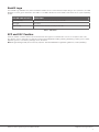
Backlit Logo
The backlit logo indicates the power and armed status of the communicator. Depending on the operation, the LED
displays in red or green as listed in the Table 1. The LED indicates the armed state and status of the system primary
power.
COLOR AND ACTIVITY OPERATION
Green Steady Communicator Disarmed, Primary Power OK
No Light No Power
Red Steady Communicator Armed, Primary Power OK
ECP and DSC Passthru
Perform an ECP or DSC Passthru and communicate through the communicator over the host panel’s bus. This
also allows users to manage host panels through Virtual Keypad including arming, disarming, viewing zone status,
bypassing zones, view history, manage users, and more.
Note: Programming a DSC panel remotely requires a Model 330‑DSC Programming Harness (sold separately).
Table 1: LED Status

Digital Monitoring Products
CellCom‑LTE
Programming and Installation Guide
4
INSTALLATION
Select a Location
Install the communicator away from metal objects. Do not mount the communicator inside or on a control panel metal
enclosure. Mounting the communicator on or near metal surfaces impairs cellular performance.
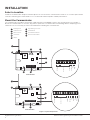
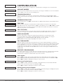
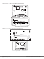
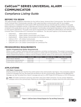
Mount the Communicator
The communicator should be mounted to a wall using the included #6 screws in the mounting holes. See Figure 1.
Mount the communicator in a secure, dry place to protect the communicator from damage due to tampering or the
elements. It is not necessary to remove the PCB when installing the communicator.
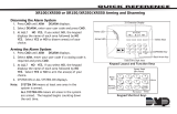
Figure 1: System Components
+DC- Z1 Z2 Z3
G
T R
+Z4-
O1 O2
+DC- Z1 Z2 Z3 G T1 R1 T2+Z4- R2O1 O2
B
C
PROG
B
R
RESETLOAD
D
H
A
GE
+DC- Z1 Z2 Z3
G
T
R
+Z4-
O1 O2
F
I
CellCom-LTE-V
PROG
B
R
RESETLOAD
D
F
H
B
C
A
GE
+DC- Z1 Z2 Z3 G T1 R1 T2+Z4- R2O1 O2
CellComF-LTE-V
A
B
C
D
E
F
G
H
Mounting Holes
Cellular Antenna
SMA Connector
Cell Modem
Tamper
Programming Connection
Terminal Block
Load and Reset Buttons
I
Power and Armed LEDs
I
DC Power
Zones 1 - 4
Tip 1
Output 1
Output 2
Ring 1
DC Power
Zones 1 - 4
Tip 1
Output 1
Output 2
Ring 1
Tip 2
Ring 2

CellCom‑LTE
Programming and Installation Guide Digital Monitoring Products
5
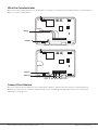
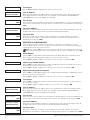
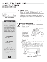
Wire the Communicator
When connecting component wires, route all wires so they will not interfere with the tamper switch. See Figure 2 and
Figure 3 for wire routing options.
Connect the Antenna
Place the antenna onto the SMA connector. Refer back to Figure 1. Twist the antenna until it is securely tightened.
Replace the housing cover on the mounted base. Be sure to not damage any PCB components when removing or
replacing the housing cover.
Figure 2: Wire Routing Option One
Wiring
PROG
B
R
RESETLOAD
+DC- Z1 Z2 Z3
G
T
R
+Z4-
O1 O2
Tamper
PROG
B
R
RESETLOAD
+DC- Z1 Z2 Z3
G
T
R
+Z4-
O1 O2
Wiring
Tamper
Figure 3: Wire Routing Option Two

Digital Monitoring Products
CellCom‑LTE
Programming and Installation Guide
6
APPLICATIONS
The communicator can be used in a variety of applications.
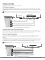
CID Dialer Connection
Directly connect one or both tip and ring terminals from the control panel to the communicator. See Figure 4. This
connection captures Contact ID messages from any fire panel that are based on the SIA communication standard
DC‑05‑1999.09‑DCS. Messages are then formatted into a Serial 3 message and sent to an SCS‑1R Receiver or SCS‑VR
Receiver.
Note: CID Dialer Connection cannot be used when using Zone 4 Bell Connection. Do not connect telephone
company wires to the communicator. Remove any connected telephone company wires from the control panel.
Communication Failure (CellComF only)
The phone line voltage on the second tip and ring will drop when the CellComF‑LTE is in a communication failure
state. This triggers the host panel to annunciate a communication failure. When communication is restored, voltage is
restored on the second tip and ring terminal and the host panel sees a restoral on the phone line.
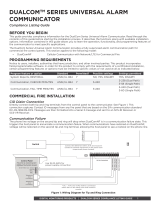
Zones 1-4 Input Connection
Connect each control panel relay output to a zone on the communicator. For programming purposes, the zone
numbers are 1‑4. The following are examples of how you might use this application for a burglary or fire alarm.
Burglary
Use a normally closed output on a burglary control panel to indicate a burglary alarm. The communicator zone should
be programmed with a zone name and burglary zone type. When the output on the control panel turns on and trips
the communicator zone, a message is sent to an SCS‑1R or SCS‑VR receiver at the central station. The zone name
programming can be used to describe which control panel zone indicated a burglary. See Figure 5.
Note: Zone4 can only be used as a standard input zone when not programmed as zone type Auxiliary2 (A2). See
Zone4 Bell Connection.
Figure 4: Wiring Diagram for Tip and Ring Connection
Use 18-22 AWG
for Power Supply
connection
CellComF-LTE-V
+DC- Z1 Z2 Z3 G T1 R1 T2+Z4- R2O1 O2
+
–
Tip 1
Ring 1
12/24 VDC Aux. Output
+
-
Ground
Control Panel
The panel or separate power
supply must be listed for fire,
regulated, and power limited.
Telephone
Jack
Connector
BELL -
BELL +
Tip 2
Ring 2
Telephone
Jack
Connector
No Connection
(Zone Inputs Not
Evaluated By UL)
Wiring to FACP shall be connected within 20 ft in the same room and routed in conduit.
If FACP only has one phone line, connect to T2, R2
+DC- Z1 Z2 Z3
G
T
R
+Z4-
O1 O2
Use 18-22 AWG for
Power Supply connection
Z3 +
Z4 +
Z4 -
GND
Aux. Output
+
-
Ground
Control Panel
The panel or separate power
supply must be 12/24 Volt
Regulated and Power Limited.
Z1 +
+
–
Z2 +
Normally Open
Common
Normally Closed
Normally Open
Common
Normally Closed
Normally Open
Common
Normally Closed
Normally Open
Common
Normally Closed
1k ohm
1k ohm
1k ohm
1k ohm
Figure 5: Wiring Diagram for Burglary Zones 1-4

CellCom‑LTE
Programming and Installation Guide Digital Monitoring Products
7
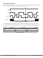
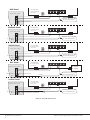
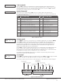
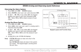
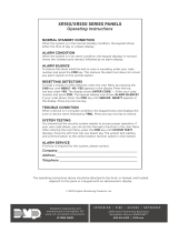
Zone4 Bell Connection
Zone4 (Z4+ and Z4‑) can be connected to the control panel bell output. This zone detects an alarm condition on the
control panel by monitoring the voltage and cadence timing of the bell output. The communicator evaluates the first
3.5seconds of bell cadence timing to detect the type of alarm sent. See Figure 6.
To enable alarm detection operation, Zone4 Bell Connection must be programmed as Zone Type (A2) in Zone
Information programming. See Table 2 for bell cadence type, zone number, and type of message sent to the receiver.
The communicator generates zones5 and6 using the zone name of zone4 to send to the central station. Zones5
and6 cannot be preprogrammed in Zone Information. CID Dialer Connection cannot be used when using Zone4 Bell
Connection.
BELL CADENCE ZONE NUMBER TYPE OF MESSAGE
Steady Zone4 Burglary
Pulse or Temporal3 Zone5 Fire
Temporal4 Zone6 Emergency or Carbon Monoxide
Table 2: Message Breakdown
Figure 6: Zone 4 Bell Cadence Information
Steady
Pulse
Temporal 3
Temporal 4
1.0 sec 1.0 sec 1.0 sec 1.0 sec 1.0 sec
0.5 sec 0.5 sec 0.5 sec 1.5 sec 0.5 sec0.5 sec 0.5 sec 0.5 sec
3.5 sec
Each 0.1 sec On
5.0 sec
On
O
On
O
On
O
On
O
Each 0.1 sec O
Each 0.1 sec On
Each 0.1 sec O

Digital Monitoring Products
CellCom‑LTE
Programming and Installation Guide
8
Figure 7: Zone 4 Bell Connection
+DC- Z1 Z2 Z3
G
T
R
+Z4-
O1 O2
Use 18-22 AWG
for Power Supply
connection
1k Ω
+
–
Z4 -
+DC- Z1 Z2 Z3
G
T
R
+Z4-
O1 O2
Use 18-22 AWG
for Power Supply
connection
1k Ω
+
–
Z4 -
+DC- Z1 Z2 Z3
G
T
R
+Z4-
O1 O2
Use 18-22 AWG
for Power Supply
connection
1k Ω
+
–
Z4 -
+DC- Z1 Z2 Z3
G
T
R
+Z4-
O1 O2
Use 18-22 AWG
for Power Supply
connection
1k Ω
+
–
Z4 -
+DC- Z1 Z2 Z3
G
T
R
+Z4-
O1 O2
Use 18-22 AWG
for Power Supply
connection
1k Ω
+
–
Z4 -
DMP Panel
12 VDC Aux. Output
+
-
ADEMCO Panel
12 VDC Aux. Output
+
-
BELL -
12 VDC BELL +
NAPCO Panel
12VDC Aux. Output
+
-
BELL -
12 VDC BELL +
DSC Panel
12/24 VDC Aux. Output
+
-
BELL -
12/24 VDC BELL +
1k
Ω
(for Supervision)
1k
Ω
(for Supervision)
2.2k
Ω
(for Supervision)
Voltages above 1.4 VDC
are considered Alarm
24 VDC Panel
12/24 VDC Aux. Output
+
-
BELL -
24 VDC BELL +
4.7k
Ω
(for Supervision if required)
Program Zone 4
DO - Alarm
AO - Alarm
1k Ω
10k Ω
Voltages above 1.4 VDC
are considered Alarm
Voltages above 1.4 VDC
are considered Alarm
Voltages above 1.4 VDC
are considered Alarm
Voltages above 0.7 VDC
are considered Alarm

CellCom‑LTE
Programming and Installation Guide Digital Monitoring Products
9
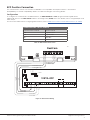
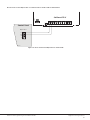
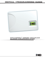
ECP Passthru Connection
The communicator can be connected to the ECP Bus of a compatible VISTA panel. Refer to “VISTA Panel
Compatibility” for VISTA compatibility details. See Table 3 and Figure 8 for wiring details.
Configuration
To configure the communicator for ECP Passthru, set KEYPAD INPUT to ECP, program VISTA keypad device
address20, then use the ECP SETUP feature in the Diagnostics (DIAG) menu. For details, refer to “Keypad Input” and
“ECP Setup”.
For more information about configuring ECP Passthru, refer to COM Series How‑To Guide: ECP Passthru (LT‑2209).
PROG
B
R
RESETLOAD
+DC- Z1 Z2 Z3
G
T
R
+Z4-
O1 O2
DualCom
1 2 3 4 5 6 7 8 9 10 11 12 13 14 15 16 17 18 19
20
21 22 23 24
25
+ +–
HI
HI
HI
LO
LO
LO
LO
HI
HI
LO
LO
HI
HI
LO
LO
HI
TIP
(BROWN)
RING
(GRAY)
TIP
(GREEN)
RING
(RED)
+
-
BLACK
RED
SYNC
COM
DATA
(USE SA4120XM-1
CABLE)
1 2 3 4 5 6 7 8
OUT 17
+12 AUX
GND
OUT 18
VISTA 20P ONLY
VISTA-20P
From DC+
From DC–
From Z4+
From Z4-
To Data In (6)
To Data Out (7)
To Negative (4)
To Positive (5)
RED
BLACK
GREEN
YELLOW
RED
BLACK
GREEN
YELLOW
RED
BLACK
GREEN
YELLOW
Figure 8: ECP Passthru Wiring
COMMUNICATOR TO ECP WIRING
Communicator Terminal VISTA Terminal
+DC Keypad Power
‑DC Keypad GND
Z4+ Data Out
Z4‑ Data In
Table 3: ECP Terminal Connections

Digital Monitoring Products
CellCom‑LTE
Programming and Installation Guide
10
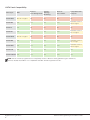
VISTA Panel Compatibility
Panel Type ECP
Remote
User Management
Remote
Arming/
Disarming
Remote
Zone Status
Compatible with
Compass
VISTA‑10SE Rev 15 or higher No No No No
VISTA‑10P Yes Yes Yes Yes
Firmware version
2.0 or higher
VISTA‑15 Yes No No No No
VISTA‑15P Yes Yes Yes Yes
Firmware version
5.2 or higher
VISTA‑20SE Rev 12 or higher No No No No
VISTA‑20P Yes Yes Yes Yes
Firmware version
5.2 or higer
VISTA‑20PI Yes Yes Yes Yes
Firmware version
5.0 or higher
VISTA‑21iP Yes Yes Yes Yes Yes
VISTA‑21iPLTE Yes Yes Yes Yes Yes
Note: Panels must be programed in the Stay/Away mode for Remote Arming/Disarming (No Partitions).
Vista 32, 40, 50, 128, 250 are not compatable with ECP Virtual Keypad and eSuite.

CellCom‑LTE
Programming and Installation Guide Digital Monitoring Products
11
PROG
B
R
RESETLOAD
+DC- Z1
Z2 Z3
G
T
R
+Z4-
O1 O2
+DC- Z1
Z2 Z3
G
T
R
+Z4-
O1 O2
CellCom
ETHERNET
DSC PC1864
AC AC +AUX- +BELL- RED BLK YELGRN 1 PGM 2 3 PGM 4 Z1 COM Z2 Z3 Z4 Z5 Z6 Z7 Z8
EGND RING TIP
R-1 T-1COM COM COM
AC +AUX-
+BELL- RED BLK YEL GRN 1 PGM 2 3 PGM 4 Z1 COM Z2 Z3 Z4 Z5 Z6 Z7 Z8
EGND
A
RING
B
TIP
C
R-1
D
T-1
COM COM COM
1k Ω
EOL
5.6k Ω EOL
To AC
Power
From DC +
From DC -
From Z4 +
From Z4 -
From T
To RED
To BLK
To YEL
To TIP
To RING
To GRN
From R
RED
BLACK
BLACK
BLACK
YELLOW
GREEN
GREEN
RED
Remote
Programming
Connection
(Model 330-DSC)
PC LINK
1
CON 4
YELLOW
GREEN
YELLOW
GREEN
TAB
UP
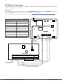
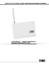
Figure 9: DSC Passthru Wiring
COMMUNICATOR TO DSC WIRING
Communicator
Terminal
DSC Terminal
DC+ RED
DC‑ BLK
Z4+ YEL
Z4‑ GRN
T or T1 TIP
R or R1 RING
N/A Bell+ to Bell‑ (1k Ω EOL)
N/A Zones 1 ‑ 8 (5.6k Ω EOL)
PROG PC Link (COM) Tab Up
Table 4: DSC Terminal Connections
DSC Passthru Connection
The communicator can be connected to the DSC Bus of a DSC PowerSeries Model PC1616, PC1832, or PC1864. Refer
to Table 4 and Figure 9 for wiring details.
Configuration
To configure the communicator for DSC Passthru, set KEYPAD INPUT to DSC and use the DSC SETUP feature in the
Diagnostics (DIAG) menu. For details, refer to “Keypad Input” and “DSC Setup”.
For more about configuring DSC Passthru systems, refer to COM Series How‑To Guide: DSC Passthru (LT‑2208).

Digital Monitoring Products
CellCom‑LTE
Programming and Installation Guide
12
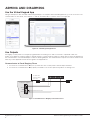
ARMING AND DISARMING
Use the Virtual Keypad App
Using a smartphone with the DMP Virtual Keypad App or a computer with VirtualKeypad.com, you can connect to the
communicator to arm areas, turn outputs on and off, and add, edit, or remove users. See Figure 10.
Use Outputs
A burglary control panel zone may be programmed as an arming zone and connected to output O1 or O2. See
Figure 11. Program the output number in armed output or remote arming output in output options when programming
the communicator. See Armed Output or Remote Arming Output. The communicator output connections can be used
with any of the applications listed in this guide. See Applications.
Communicator to Panel Burglary Zones
1. Connect the communicator’s Z1 (zone 1) terminal to the control panel’s armed output terminal.
2. Connect the communicator’s O1 (output 1) terminal to the control panel’s keyswitch or arming zone.
Figure 10: Virtual Keypad Applications
Figure 11: Communicator to Burglary Control Panel Zones
+DC- Z1
Z2 Z3
G
T
R
+Z4-
O1 O2
+
–
Use 18-22 AWG
for Power Supply
connection
O2
12 VDC Aux. Output
+
-
GND
Zone 1
Zone 2
Control Panel EOL resistor

CellCom‑LTE
Programming and Installation Guide Digital Monitoring Products
13
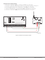
Honeywell Vista 20 Panel Wiring
1. Connect the communicator’s Z1 (zone 1) terminal to output 17 on the control panel.
2. Connect the communicator’s O1 (output 1) terminal to the control panel’s keyswitch or arming zone.
3. Connect the T (tip) terminal on the communicator to terminal 23 on the control panel.
4. Connect the R (ring) terminal on the communicator to terminal 24 on the control panel.
5. Power the communicator by connecting its terminal +12V to terminal 5 on the control panel.
6. Connect the communicator’s GND (ground) terminal to terminal 4 on the control panel.
PROG
B
R
RESETLOAD
+DC- Z1
Z2 Z3
G
T
R
+Z4-
O1 O2
CellCom-LTE-V
1 2 3 4 5 6 7 8 9 10 11 12 13 14
15
16 17 18 19
20
21 22 23 24
25
Honeywell Vista 20 Series
OUTPUT 17
Connect to any
keyswitch or arming
zone.
Figure 12: Vista 20 Series Control Panel to CellCom

Digital Monitoring Products
CellCom‑LTE
Programming and Installation Guide
14
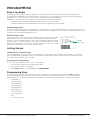
ACTIVATE THE CELLULAR MODULE
For more information about using Dealer Admin, Tech APP, or Remote Link, refer to DMP.com/dmphelp.
Dealer Admin Activation
1. Find the customer and select their name.
2. The customer’s summary page opens. In the Systems section, press the Add icon.
3. Enter the system name.
4. In System Type, select CellComSL.
5. In Connection Type, select Cellular.
6. In SIM Number, enter the SIM number and press Get Status.
7. Press Activate.
8. In Account Number, enter the system’s receiver number followed by the account number.
9. Select a Rate Plan for the communicator.
10. Enter the panel Remote Key. The remote key must match the one programmed in panel REMOTE OPTIONS.
11. To confirm proper communication, press Test Connection.
12. A dialog pops up to ask if you want to perform the initial connection to the panel. Press Yes .
13. Configure additional options as needed, then press Save.
Tech APP Activation
1. Go to the Customer Summary > Systems.
2. Tap the Add icon.
3. Enter the System Name.
4. In System Type, select CellComSL.
5. In Connection Type, choose Cellular.
6. In Account Number, enter the system’s receiver number followed by the account number.
7. Enter the panel Remote Key. The remote key must match the one programmed in panel REMOTE OPTIONS.
8. Enter the SIM Number and tap Get MEID/SIM Status.
9. Select a Rate Plan for the communicator.
10. Configure additional options as needed, then tap Save.
Remote Link Activation
1. Go to File > Panel Information.
2. Press New.
3. In Model, select CellComSL.
4. If necessary, enter a firmware version number in Version.
5. Enter the receiver number and account number, then press OK.
6. In Connection Information, select Cellular.
7. Enter the panel Remote Key.
8. Enter the cellular Phone Number.
9. Press OK.
10. Go to Program > Communications.
11. In Connection, press Activate.
12. Select SIM as the SIM Type.
13. Enter the SIM number, then select a Rate Plan.
14. Press Activate.

CellCom‑LTE
Programming and Installation Guide Digital Monitoring Products
15
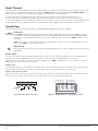
PROGRAMMING
Before You Begin
Read this guide before you begin programming. This guide allows you to quickly learn the programming options
and operational capabilities of the CellCom‑LTE communicator. The communicator contains all of its programming
information in an on‑board processor and does not require an external programmer.
In addition to this manual, you should also be familiar with the following document:
• CellCom‑LTE Series Universal Alarm Communicator User Sheet (LT‑1819)
• CellCom‑LTE Series Universal Alarm Communicator Programming Sheet (LT‑1818)
Programming Sheet
Fill out the programming sheet included with this device before you begin programming. The programming sheet lists
the various options available for programming the communicator and allows you to keep a record of what options you
intend to enter, reducing programming errors.
Default Master Code
Universal Communicators Version 194 and higher ship with a unique four‑digit
default master code. This master code is generated with an algorithm that
ensures it cannot be duplicated. The code can be modified or deleted in panel
programming. To revert the default code to99, use the Clear All Codes option
found in the Initialization menu. Panels ship with the master code on the serial
number label in parentheses next to the serial number.
Getting Started
Initializing the Communicator
When programming a communicator for the first time or rewriting the entire program of an existing communicator,
use the initialization programming option. See Initialization. Initializing clears the communicator’s memory and sets
the highest user number to user code 99.
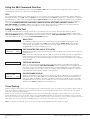
Accessing the Programmer
To access the programmer function of the
communicator
:
1. Connect the keypad to the programming header.
2. Press and release the reset button.
3. Enter 6653 (PROG). The keypad displays PROGRAMMER.
Programming Menu
The following is a list of programming menu options available in the programming menu. Press CMD to advance
through the programming menu options. To select a menu option, press any select area when the desired menu
option displays on the keypad. Use this list to navigate to your desired programming menu option in this guide.
• Initialization
• Communication
• Remote Options
• System Reports
• System Options
• Output Options
• Area Information
• Zone Information
• Stop
• Set Lockout Code
MAC : 00:01:22:33:44:55
MOD : DUALCOM
VER : 194 122319
SN : 0012345A (21852)
TD : 011520
KEY : 100
Default
User Code

Digital Monitoring Products
CellCom‑LTE
Programming and Installation Guide
16
Reset Timeout
You must enter the programmer menu within 30minutes of resetting the communicator to avoid reset timeout. After
30minutes, if you attempt to program by entering the 6653 (PROG) code, the keypad displays RESET PANEL. You
must reset the communicator and enter the program code within the next 30minutes.
If you are already in the programmer menu and do not press any keys on the keypad for 30minutes, the
communicator
exits programming. All data entered up to that point is saved in the communicator memory.
To exit the programmer menu, use the stop option. The stop option is the second‑to‑last option in programming and
disarms all areas. The programming session is terminated and the keypad returns to status list or main screen.
Special Keys
The following keys and areas are common to all DMP LCD and graphic touchscreen keypads.
Command
Press CMD to advance through the programmer menu and through each step of a programming section.
As you advance through the programmer menu, the keypad display any current programming already
stored in the communicator memory. If no change is required for an option, press CMD to advance to the
next step.
CMD is also used to enter information into the communicator’s memory such as an IP address or a zone
name. Press CMD after entering information.
Back Arrow
Use the back arrow to back up one step in a programming menu or to erase a typing error while entering
information.
Select Areas
The top row of keys on LCD Keypads are called select areas. The select areas on graphic touchscreen keypads are
along the top of the keypad. When you need to press a select area, the keypad displays the options.
When there are more than four re sponse options avail able, press CMD to display the next set of options. Press the
back arrow to return to the previous options.
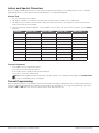
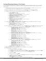
LCD Keypads
The first select area is on the far left. The second select area is second from the left. The third select area is second
from the right. The fourth select area is on the far right and is for special characters. See Figure 13.
Graphic Touchscreen Keypads
When instructed to press the first select area, touch select area 1; the second select area, touch select area2; third
select area, touch select area3; and the fourth select area, touch select area 4. See Figure 14.
CMD
Figure 13: LCD Keypad Select Keys Figure 14: Graphic Touchscreen Keypad Select Areas
First Letter
Second Letter
Third Letter
Special Character
(
CBA
32-Character Display
Select Area 1
Select Area 3
Select Area 2
Select Area 4
Page is loading ...
Page is loading ...
Page is loading ...
Page is loading ...
Page is loading ...
Page is loading ...
Page is loading ...
Page is loading ...
Page is loading ...
Page is loading ...
Page is loading ...
Page is loading ...
Page is loading ...
Page is loading ...
Page is loading ...
Page is loading ...
Page is loading ...
Page is loading ...
Page is loading ...
Page is loading ...
Page is loading ...
-
 1
1
-
 2
2
-
 3
3
-
 4
4
-
 5
5
-
 6
6
-
 7
7
-
 8
8
-
 9
9
-
 10
10
-
 11
11
-
 12
12
-
 13
13
-
 14
14
-
 15
15
-
 16
16
-
 17
17
-
 18
18
-
 19
19
-
 20
20
-
 21
21
-
 22
22
-
 23
23
-
 24
24
-
 25
25
-
 26
26
-
 27
27
-
 28
28
-
 29
29
-
 30
30
-
 31
31
-
 32
32
-
 33
33
-
 34
34
-
 35
35
-
 36
36
-
 37
37
-
 38
38
-
 39
39
-
 40
40
-
 41
41


DMP Electronics CellCom LTE Series Programming And Installation Manual
- Type
- Programming And Installation Manual
- This manual is also suitable for
Ask a question and I''ll find the answer in the document
Finding information in a document is now easier with AI
Related papers
-
DMP Electronics CellCom-LTE-V SERIES Installation And Programming Manual
-
 DMP Electronics XR150 Reference guide
-
 DMP Electronics DUALCOM Series Compliance Listing Manual
-
 DMP Electronics XR500 SERIES User manual
-
 DMP Electronics CCKPC0159 User manual
-
 DMP Electronics CellCom series Compliance Listing Manual
-
 DMP Electronics SCS-1R Installation guide
-
-
 DMP Electronics SCS-105 Installation guide
-
 DMP Electronics SCS-105 Installation guide


Other documents
-
 Digital Monitoring Products ECP Passthru User guide
-
 Digital Monitoring Products DSC PassThru User guide
-
 Digital Monitoring Products ECP Passthru User guide
-
 Digital Monitoring Products DSC PassThru User guide
-
 Digital Monitoring Products XR150/XR550 Series Panels Operating instructions
-
 Digital Monitoring Products Cell ComSL Programming Guide
-
 Digital Monitoring Products XT Series International User guide
-
 Conway Corp Technicolor TCA203 TouchScreen Quick start guide
-
 Digital Monitoring Products PowerCom Fire Installation & Programming Guides
-
 Digital Monitoring Products PowerCom Fire Installation & Programming Guides


