Page is loading ...

DIGITAL MONITORING PRODUCTS | DUALCOM SERIES COMPLIANCE LISTING GUIDE 1
BEFORE YOU BEGIN
This guide provides compliance information for the DualCom Series Universal Alarm Communicator. Read through the
contents of this guide before starting the installation process. It describes the functions along with available installation
options. Information contained in this guide allows you to learn the operation, functionality, and programming features of
the communicator to meet specific applications.
The DualCom Series Universal Alarm Communicator provides a fully supervised alarm communication path for
commercial control panels. This section applies to the following models:
• DualComNF Cellular Communicator with Network/LTE for Commercial Fire
• DualComNF-FN Cellular FirstNet Communicator with Network/LTE for Commercial Fire
• DualComN Cellular Communicator with Network/LTE for Commercial Burglary
PROGRAMMING REQUIREMENTS
Notice to users, installers, authorities that have jurisdiction, and other involved parties: This product incorporates
field-programmable software. In order for the product to comply with the requirements of a certificated installation,
certain programming features or options must be limited to specific values or not used at all as indicated below.
Program feature or option Standard Permitted? Possible settings Settings permitted
System Reports, RESTORAL ANSI/UL 864 Y NO, YES, DISARM YES, DISARM
Communication, CHECKIN MINUTES ANSI/UL 864 Y 3-240 3-238 (Dual Path)
3-58 (Single Path)
Communication, FAILTIME MINUTES ANSI/UL 864 Y 3-240 3-240 (Dual Path)
3-60 (Single Path)
COMMERCIAL FIRE INSTALLATION
CID Dialer Connection
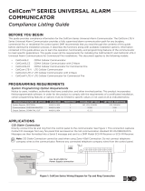
Directly connect both tip and ring terminals from the control panel to the communicator. See Figure 1. This
connection captures Contact ID messages from any fire panel that are based on the SIA communication standard
DC-05-1999.09-DCS. Messages are then formatted into a Serial 3 message and sent to an SCS-1R Receiver or
SCS-VRReceiver.
Communication Failure
The phone line voltage on the second tip and ring will drop when DualComNF is in a communication failure state. This
triggers the host panel to annunciate a communication failure. When communications have restored on DualComNF,
voltage will be restored on the second tip and ring terminal, allowing the host panel to see a restoral on the phone line.
DUALCOMTM SERIES UNIVERSAL ALARM
COMMUNICATOR
Compliance Listing Guide
Figure 1: Wiring Diagram for Tip and Ring Connection
LOAD RESET
ETHERNET
+DC- Z1 Z2 Z3 G +Z4- 01 02 T1 R1 T2 R2
Use 18-22 AWG for
power supply connection
CONTROL PANEL TIP
CONTROL PANEL RING
12/24 VDC Aux. Output +
-
Ground
Control Panel
The panel or separate power
supply must be listed for fire,
regulated, and power limited.
Telephone
Jack
Connector
BELL -
BELL +
CONTROL PANEL TIP
CONTROL PANEL RING
Telephone
Jack
Connector
No Connection
(Zone Inputs Not
Evaluated By UL)
Switch
(CellComDF Only) Connect the Ethernet within 20 ft and routed in
conduit to network equipment in the same room (supervised, power limited).
Wiring to FACP shall be connected within 20 ft in the same room and routed in conduit.
If FACP only has one phone line, connect to T2, R2

2 DUALCOM SERIES COMPLIANCE LISTING GUIDE | DIGITAL MONITORING PRODUCTS
ANSI/UL 864
Fire Protective Signaling Systems using Internet/Intranet/Cell Networks
A Performance Based Technologies system as defined in UL 864 10th Edition may be configured as the following:
Network Primary and Cellular Backup Programming
Network Programming Cellular Programming
Comm Type = NET Comm Type = CELL
Checkin Min = 238 Checkin Min = 238
Failtime Min = 240 Failtime Min = 240
Cellular Primary with no Backup
Path 1 Programming
Comm Type = CELL Checkin Min = 58
Path Type = Primary Failtime Min = 60
Test Rpt = No Checkin = Yes
Network Primary with no Backup
Path 1 Programming
Comm Type = NET Checkin Min = 58
Path Type = Primary Failtime Min = 60
Test Rpt = No Checkin = Yes
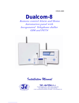
Model 685-R Backbox Installation
For Commercial Fire applications using DualComNF and the included red plastic Model 685-R backbox, mount the
backbox to the wall with the 1” #6 screws included with the fire communicator. Mount the fire communicator to the
backbox with the 1/2” #6 screws. See Figure2. Locate the fire communicator within 20 feet of the control panel and
route all wire in conduit.
Refer to the DualCom Series Programming and Installation Guide (LT-1859) for communication test procedure.
Cellular Communication Failure Test Procedure
For commercial fire systems, the following test procedure can be used to demonstrate local annunciation of a
communication path failure where required by the AHJ.
1. Connect the communicator to the FACP as shown in Figure 1 and program the communicator according to the tables
above.
2. Program the appropriate settings for the central station receiver and allow the communicator to check in with the
receiver.
3. Enter the programming menu and change the receiver port number to an invalid (closed) port.
4. Exit programming and allow the communicator to resume operation.
5. The communicator will unsuccessfully attempt to communicate and then drop the voltage on the second tip and ring
terminals which will cause the FACP to annunicate a phone line trouble.
6. After successfully demonstrating local annunciation, return to the programming menu and change the receiver port
back to the correct (open) port to verify communication.
# 6 Screws Included
with Backbox
Network Cable
Routing Locations
Figure 2: Model 685-R Backbox Installation

DIGITAL MONITORING PRODUCTS | DUALCOM SERIES COMPLIANCE LISTING GUIDE 3
NEW YORK CITY (FDNY) SPECIFICATIONS
Introduction
The programming specifications contained in this section must be completed when installing Com Series Communicators
for New York City (FDNY) fire alarm IP communication applications. Refer to the FDNY Certificate of Approval #6262 for
the complete conditions of approval.
Network and Cellular Communication, Primary and Secondary
When installed as a central station Internet (Network) communicator or slave transmitter, both primary and secondary
channels of communication shall be required and shall meet the conditions below. Network communication shall be
used as the primary channel of communication to the Central Station and a Cellular Communicator shall be used as the
secondary channel of communication or in reverse order: Cellular Communicator as the primary channel and Network
connection as the secondary channel.
Network Primary And Cellular Backup Programming
NETWORK PROGRAMMING CELLULAR PROGRAMMING
Comm Type = NET Comm Type = CELL
Checkin Min = 5 Checkin Min = 5
Failtime Min = 5 Failtime Min = 5
Test Rpt = Yes Test Rpt = Yes
Test Freq = 1 Dy Test Freq = 1 Dy
Cellular Primary and Network Backup Programming
CELLULAR PROGRAMMING NETWORK PROGRAMMING
Comm Type = CELL Comm Type = NET
Checkin Min = 5 Checkin Min = 5
Failtime Min = 5 Failtime Min = 5
Test Rpt = Yes Test Rpt = Yes
Test Freq = 1 Dy Test Freq = 1 Dy

Designed, engineered,
and manufactured in
Springfield, Missouri using U.S.
and global components.
LT-1899 21522 1.01
INTRUSION • FIRE • ACCESS • NETWORKS
2500 North Partnership Boulevard
Springfield, Missouri 65803-8877
800.641.4282 | DMP.com
Certifications
New York City (FDNY) (DualComNF)
California State Fire Marshal (CSFM) (DualComNF)
Cellular
FCC Part 15: XMR201707BG96
XMR201907BG95M3
XMR201909EC25AFX
IC: 10224A-201709BG96
10224A-2019BG95M3
110224A-2019EC25AFX
Underwriters Laboratories (UL) Listed
DualComNF/DualComNF-FN
New York City (FDNY)
Underwriters Laboratory (UL) Listed
ANSI/UL 864 Fire Protective Signaling Systems
(CID Capture)
DualComN
ANSI/UL 1610 Central Station Burglar
Specifications
Primary Power Nominal 12 - 24VDC
DualComNF/DualComN
Current Draw at 12VDC
Standby 75mA
Alarm 96mA Peak Cellular Communication
Current Draw at 24VDC
Standby 45mA
Alarm 85mA Peak Cellular Communication
DualComNF-FN
Current Draw at 12VDC
Standby 75mA
Alarm 134mA Peak Cellular Communication
Current Draw at 24VDC
Standby 45mA
Alarm 99mA Peak Cellular Communication
Dimensions and Color
DualComNF
Housing Dimensions 5.5”W x 3.75”L x 1”H
Housing Color Red
DualComN
Housing Dimensions 5.5”W x 3.75”L x 1”H
Housing Color White
DUALCOM SERIES UNIVERSAL
ALARM COMMUNICATOR
/