M2M SERVICES MQ03-LTE-M-FIRE User manual

Type
User manual

M2M SERVICES MQ03-LTE-M-FIRE is a digital cellular communicator with a dial capture interface that offers exceptional redundancy with dual-SIM support for AT&T and Verizon LTE CAT M1 networks. It ensures high reliability through multiple transmission channels (LTE CAT M1/LAN) and redundant servers.

M2M SERVICES MQ03-LTE-M-FIRE is a digital cellular communicator with a dial capture interface that offers exceptional redundancy with dual-SIM support for AT&T and Verizon LTE CAT M1 networks. It ensures high reliability through multiple transmission channels (LTE CAT M1/LAN) and redundant servers.

MQ03-LTE-M-FIRE
Cellular Communicator with Dial Capture interface
Installation and Operation Manual
Doc. No. 03002 V 1.1 08/2020
© M2M Services
1 Kukush Str, building M8
Sofia 1309, Bulgaria www.m2mservices.com
About this document
This document was developed and wholly owned by M2M Services. It is intended
to assist trained personnel with the installation of MQ03-LTE-M-FIRE. M2M Services
reserves the right to modify and revise this manual without notice.
Agency Listings and Approvals
These listings and approvals apply only to the module specified in this document. In
some cases, the listing may be in process.
FCC Statement
This equipment complies with FCC rules Part 15, FCC registration No. XMR201707BG96
and operation is subject to the following conditions:
- This device may not cause harmful interference, and
- This device must accept any interference received.
ETL No. 5013005, conforms to the following UL standards:
CAL FIRE OSFM BML No. 7300-2329:0500
UL 864 – Control Units and Accessories for Fire Alarm Systems
UL 1610 – Central-Station Burglar Alarm Units
Limited Liability
The user agrees that despite the Device could reduce the risk of fire, theft, burglary
or other dangers, it does not guarantee against such events. M2M Services will not
take any responsibility regarding personal, property or revenue loss while using the
Device. M2M Services responsibility according to local laws does not exceed the
value of the purchased system. M2M Services is not affiliated with GSM operators
providing cellular services, therefore is not responsible for network services,
coverage or its operation.
Manufacturer Warranty
The Device carries a non-transferable hardware limited warranty by the
manufacturer M2M Services. This warranty does not cover any postal or labor costs
for the removal and reinstallation of the Device. This warranty does not cover any
subscriber agreements or failure of services provided under the terms of such
subscriber agreements, or failure of cellular, GPRS, LAN or other related networks
functions and services. The warranty does not apply to any Device that has been
modified or used in a manner contrary to its intended purpose and does not cover
damage to the Device caused by installation or removal of the Device or any of its
components. This warranty is voided if the Device has been damaged by improper
maintenance, SIM card removal, accident or unreasonable use, negligence, acts
of God, neglect, improper service or other causes not arising out of defect in
materials or construction. This warranty does not cover the elimination of externally
generated static or noise, or the correction of antenna problems or weak signal
reception, damage to software, accessories or alarm system external components,
cosmetic damage or damage due to negligence, misuse, abuse, failure to follow
operating instructions, accidental spills or customer applied cleaners, damage
due to environmental causes such as floods, airborne fallout, chemicals, salt, hail,
windstorms, moisture, lightning or extreme temperatures, damage due to fire, theft,
loss or vandalism, damage due to improper storage and connection to equipment
of another manufacturer, modification of existing equipment, faulty installation or
short circuit.
In no event will M2M Services be liable for any incidental, special or consequential
damages (including loss of profits), and the Client shall have no claim against M2M
Services for termination of contracts, indemnification, compensation for loss of
customers, loss of profits, prospective profits, distribution rights, market share,
goodwill, investments made or any similar losses that may result from any faults in
the operation of the Device and the services provided by M2M Services.
Safety Instructions
This unit must be checked by a qualified technician once a year.
LTE CAT M1 communicator MQ03-LTE-M-FIRE (the Device) contains a radio transceiver
operating in LTE CAT M1 bands.
Do not use the Device with medical devices, or where it can interfere with other
devices and cause any potential danger.
Do not expose the Device to high humidity, chemical environment or mechanical
impacts.
Do not use the Device in a hazardous environment. Don’t store or install the Device in
overheated, dusty, wet or overcooled places.
The Device is mounted in limited access areas. Any system repairs must be done only
by qualified, safety aware personnel. Don’t disassemble or refit the Device. Do not
attempt to personally repair it.
Mains power must be disconnected before any installation or tuning work starts. The
device installation or maintenance must not be done during stormy conditions.
The device must be powered by DC 12-29V, 200mA power supply.
Blown fuses or any other components of the Device must not be replaced by the user.
Keep the Device dry. Any liquid, i.e. rain, moisture, may destroy or damage the inside
circuitry.
Handle carefully. Don’t vibrate or shake it violently.
Please read the user manual carefully before installation and operation of the Device.
Otherwise, it may not work properly or be destroyed.
Technical Support
For support in the USA and Canada, contact M2M Services Technical Support at:
Telephone: 1-800-403-7029
Email: support@m2mservices.com Website: support.m2mservices.com
Product Description
The MQ03-LTE-M-FIRE is a digital cellular communicator with a dial capture interface.
It represents the latest communication technology for the security industry. The new
LTE CAT M1 connectivity brings better indoor signal penetration and greater stability.
The communicator is equipped with dual-SIM sand supports multiple cellular
networks.
This communication solution is a complete communication platform for data transfer
from alarm systems at remote sites to Central Monitoring Stations (CMS). The platform
allows bi-directional data transmission by using LTE CAT M1 networks and/or LAN.
Main Features
Universal Panel Compatibility – Dial capture interface supporting Contact ID
and SIA;
Exceptional Redundancy – Dual-SIM, supporting AT&T and Verizon LTE CAT
M1 networks;
Connection monitoring – default 5 min polling of the cellular connection.
High reliability due to multiple transmission channels (LTE CAT M1/LAN) and
redundant servers;
Web-based software and smartphone app;
End-user smartphone app – supports push notifications.
v.02-2021-18-01_5000
MQ03-LTE-M-FIRE
Installation and Operation Manual
RControl App credentials:
Wiring and Mounting
Control Panel
MQ03-LTE-M-FIRE
Communicator
(Front-side view)
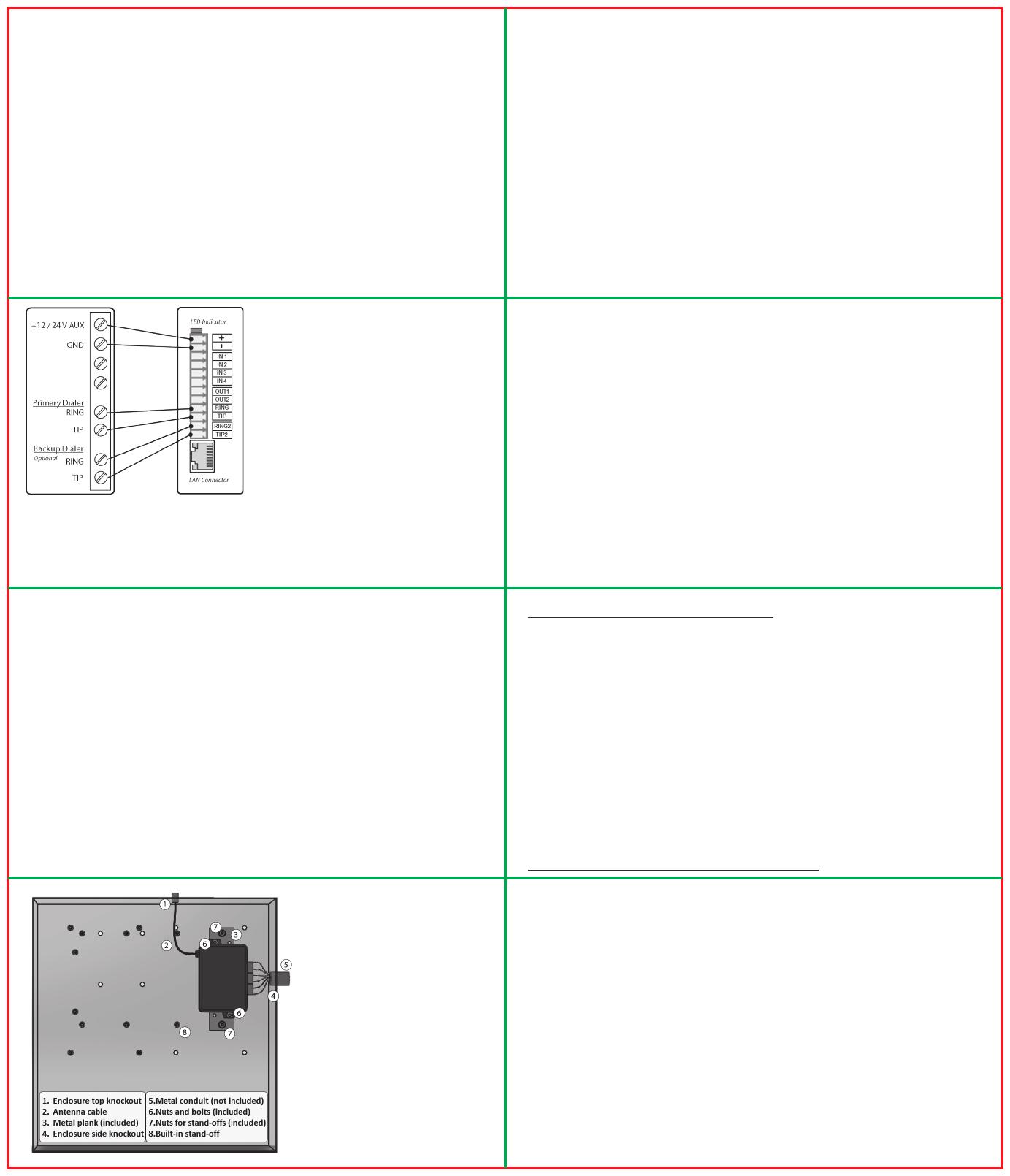
Installation Wiring Diagram
Note: IN1, IN2, IN3, IN4, OUT1, OUT2,
LAN – Not connected.
WARNINGS:
Recommended location and wiring
methods must be in accordance with the
National Electrical code, ANSI/NFPA 70.
Installation must be in accordance with
the National Fire Alarm and Signaling
Code, NFPA 72.
The communicator must be connected
to a UL Listed compatible panel with
power limited circuits.
The communicator must be powered by
a regulated UL Listed UOJZ, UTOU, NBSX
control panel or power supply.
The wiring should be done only when
the panel is powered down.
For Dry/Indoor use only.
Wiring the Communicator
The terminal strips can accommodate solid or stranded wire sizes from 14 to 22 AWG.
Mounting the Communicator
This communicator comes fully assembled with all the components mounted except
the external antenna. The device comes with a standard 3 ft external antenna.
The communicator must be installed within the Altronix BC300R metal enclosure or
as an option any other UL Listed (UOXX, NITW or CYIV) metal enclosure. All the wiring
must be routed through a conduit.
This enclosure shall have ample knockouts accommodating either ¾ or 1 conduits
for convenient access. The MQ03-LTE-M-FIRE must be attached securely to the metal
plank provided with the device, which in turn installed inside of the enclosure. The
antenna must be installed on top of the enclosure, removing one of the knockouts, as
per the installation instructions listed below in this chapter.
There are nine steps in installing
MQ03-LTE-M-FIRE properly. In
the following steps you will
use the communicator and the
RControl Admin application to
determine the signal strength
tond a suitable mounting
location.
1. For UL installations, the
communicator must be
mechanically secured to a
UL Listed enclosure such as
a UL Listed junction box. Use
the communicator box as a
template and mark the holes
on the mounting surface. Pre-
start the mounting screws
(not supplied) for these two
holes. Slide the box onto
these screws and tighten the
screws.
(+) Connect this terminal to AUX + of the panel.
(-) Connect this terminal to the AUX(GND) of the panel.
Primary Dialer RING Connect this terminal to the RING of the panel.
TIP Connect this terminal to the TIP of the panel.
Backup Dialer RING2 Connect this terminal to the RING2 of the panel.
TIP2 Connect this terminal to the TIP2 of the panel.
It is strongly recommended that both Telco lines are wired to the communicator.
2. Connect the antenna to the communicator.
The antenna is supplied with an SMA connector, that allows easy connection to
the communicator. The body of the antenna has a magnet in the bottom and can
be attached to the wall of the metal alarm panel box or use double-sided adhesive
tape to securely attach the antenna to the box. The antenna should be positioned
perpendicular to the ground, either right side up or upside down. Try to keep the
antenna away from sources of RF interference or where metal objects can shield it or
otherwise block the cellular radio RF signal.
WARNING: The internal antenna used with this product must be installed to provide
a separation distance of at least 7.8 in (20cm) from all persons and must not be co-
located or operating in conjunction with any other antenna or transmitter except in
accordance with FCC multi-transmitter product procedure.
NOTE: Antenna problems are rare unless the premises are in an area with poor
network coverage, in a building below ground, or in a metal structure. If you require
an antenna with a longer cable, please contact your M2M Services representative.
Do not use the unit with a damaged antenna. Have your antenna replaced
immediately. Use only a manufacturer approved antenna. Non-approved antennas
or modifications could impair service quality, damage the device and violate FCC
regulations.
3. Connect the communicator to the alarm panel. Refer to the wiring diagram
provided in the previous section.
4. Power up the panel.
5. The communicator LED indicator will turn on and start blinking. The steady light
will indicate a good connection. The LED has the following states:
LED StatusIndication Action
The LED is Off – The unit is not connected to the panel. Verify the wiring, refer to
the wiring diagram.
The LED is Off – The power from the panel is out. – Measure the AUX output of the
panel.
The LED is Off – The unit is damaged. Replace the unit.
Slowashing – Trying to establish connection./There is no signal available.
Reposition the antenna.
Constantly On, blinking every 5sec – Connection established at low signal level.
Reposition the antenna.
Constantly On – Connection established at good signal.
Fast flashing Transferring data
6. Download the RControl Admin mobile application on your Android or iOS device.
7. Login with the end user credentials provided in this manual.
For more details follow the M2M Smartphone Application instructions at
http://support.m2mservices.com/mobile-app/
8. If the signal is low, reposition the antenna and try again to find a better signal.
9. Once the installation and wiring is complete, proceed with the programming of
the panel (next section).
Programming
Out of the box, the communicator is ready to use and does not require additional
programming. You need to program the control panel to work with MQ03-LTE-M-FIRE.
Programming the Control Panel
For programming information, please refer to the control panel’s installation guide.
Ensure the following programming is done:
Enable the PSTN dialer of the panel
Select DTMF mode (tone dialing)
Select Contact ID or SIA communication format
Enter a telephone number for dialing (you can use any number, e.g. 999999)
Enter a 4-digit account number
Programming guides for popular alarm panels are available at
http://support.m2mservices.com/panel-programming/
Troubleshooting
If you have issues receiving the events:
1. Verify the RING/TIP connection
Make sure the RING/TIP terminals of the device are connected to Telco terminals
of the panel, not R-1/T-1 terminals.
2. Try the following additional settings of the panel:
Disable Wait for Dial Tone option
Use A instead of “0 in the account number
If there is more than one phone number entered, configure an account number
for each.
v.02-2021-18-01_5000v
Specifications
Supply Voltage +12 to +29 VDC
Consumption Standby 50 mA; Peak 200mA
Frequency LTE Cat M1 700/850/1700/1900/2100 MHz
GSM Providers AT&T, Verizon, or other available networks
Dimensions 2.48”x3.54”x1.26
Weight 2.56 oz without antenna
Environmental Operating temperature: 0°C to 49°C (32°F to 120°F)
Humidity: 0 to 85% relative humidity, non-condensing
  • Page 1 1
  • Page 2 2

M2M SERVICES MQ03-LTE-M-FIRE User manual

Type
User manual

M2M SERVICES MQ03-LTE-M-FIRE is a digital cellular communicator with a dial capture interface that offers exceptional redundancy with dual-SIM support for AT&T and Verizon LTE CAT M1 networks. It ensures high reliability through multiple transmission channels (LTE CAT M1/LAN) and redundant servers.

Ask a question and I''ll find the answer in the document

Finding information in a document is now easier with AI