Page is loading ...

IMPORTANT SAFEGUARDS
READ AND FOLLOW ALL SAFETY INSTRUCTIONS.
When using electrical equipment, basic safety precautions should always be followed including the following:
• DISCONNECT AC POWER SUPPLY BEFORE SERVICING.
• Installation and servicing of this equipment should be performed by qualified service personnel only.
• Ensure that the electrical wiring conforms to the National Electrical Code NEC® and local regulations, if
applicable.
• Do not mount near gas or electrical heaters.
• Equipment should be mounted in locations and at heights where it will not be readily subjected to tampering
by unauthorized personnel.
• The use of accessory equipment not recommended by the manufacturer may cause an unsafe condition.
• Any modification or use of non-original components will void the warranty and product liability.
• Do not use this equipment for other than intended use.
SAVE THESE INSTRUCTIONS!
Technical Support ■ (623) 580-8943 ■ [email protected]
AXB
Installation Instructions
20070157 REV 2 - 06/21 1 800-533-3948 www.barronltg.com

Installation
1. Insert anchor bolts in concrete with approximately 2” of exposed threads
in a 2” x 2” square pattern. Use anchor plate template on Page 3 for
alignment, centering around conduit. (Fig. 1)
2. Run the electrical wires (4ft minimum) through the bollard base.
3. Slide the bollard base over the anchor bolts after the concrete cures.
(Fig. 2)
4. Using the washers and nuts provided, loosely tighten the nuts on the
anchor bolts.
5. Level bollard base as needed. Leveling screws are not provided.
6. Tighten all four bollard bolts after leveling the bollard base.
7. Remove the lamp assembly from the bollard tube. (Fig. 3)
8. Slide wires through the bollard tube.
9. Slide the bollard tube over the bollard base and tighten the set screws.
(Fig. 4)
10. Make electrical connections; see Electrical Connections section.
11. Re-install the lamp assembly to the bollard tube and tighten the set
screws.
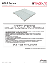
Fig. 1 - Anchor Bolt Dimensions
0.331in
5.28in
2.00in
2.84in
1.161in
2.00in
30°
30°
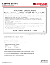
Fig. 2 Spring
Washer
Round
Screw
Washer
M8 SS
Nuts
Leveling
Screws
(Provided
By Others)
Bollard
Base
Anchor Bolts
(Approximately
2” exposed)
Fig. 3
Lamp Assembly
Bollard Tube
M8x16
Set Screws
Fig. 4
Round
Bollard
M8x16
Set Screws
AXB
Installation Instructions
20070157 REV 2 - 06/21 2 800-533-3948 www.barronltg.com

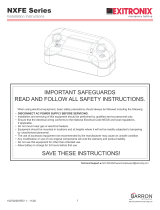
Electrical Connections (Fig. 5)
All electrical connections should be made inside the junction box. Make electrical connection as follows:
120-277VAC
Black - 120-277VAC
White - Common
Green - Ground
Note: Cap unused leads to prevent shorting.
This fixture auto-adjusts for voltages from 120-277VAC.
Troubleshooting
If the fixture does not turn ON:
1. Check incoming voltage to the LED driver. On the Switch/Un-switch line, the voltage must be a minimum of 120VAC
and no greater than 277VAC.
2. Are all LEDs on the light engine OFF? If so, the LED driver may be defective. Using a voltmeter, check to see if voltage
is present at the output of the power supply. If low or no voltage is found, replace the power supply.
3. If any individual LEDs are OFF, the LED light engine may be defective. Please have the serial number of the light
engine available when you contact technical support.
Anchor Plate Template
Important: Print actual size
Fig. 5
LED MODULE
GND
LED+
LED-
DIM+
DIM-
L
N
AC-L
AC-N
Driver Plate
SCALE 1:1
2”
3”
2”
3”
AXB
Installation Instructions
20070157 REV 2 - 06/21 3 800-533-3948 www.barronltg.com
/