Page is loading ...

INSTALLATION AND PROGRAMMING GUIDE
780 Keypad
Demonstrator Module


About the 780 ............................................. 1
Compatibility .......................................................... 1
Included Items ....................................................... 1
780 Features ...............................................2
Install the 780 .............................................3
Mount the Demo Module .................................. 3
Power Up to Demo Module ............................. 4
Connect the Keypad .......................................... 6
Program Keypads for Demonstrations ....8
Icon Series Keypad ............................................. 8
Thinline™ Keypad ................................................. 8
Keypad Address ................................................... 8
Keypad Mode ....................................................... 8
7800 Keypad ......................................................... 9
Keypad Address ................................................... 9
Keypad Mode ....................................................... 9
TABLE OF CONTENTS
Program Keypads for Fire Panic
Demonstrations ........................................10
Icon Series Keypad ............................................10
Fire Key (F 1) ........................................................10
Thinline Keypad ....................................................11
7800 Keypad .........................................................11
Arm Panic Keys ................................................... 11
Arm Panic Keys ................................................... 11
Program the Graphic Keypad for
Z-Wave Demonstrations .......................... 12
Program an Arming System
for the 780 ................................................. 13
Icon Series Keypad ............................................13
All/Perimeter ........................................................13
Home/Sleep/Away ............................................. 13
Thinline Keypad ...................................................14
7800 Keypad ........................................................14
Programer .............................................................14
Arming System ...................................................14
Programer .............................................................14
Arming System ...................................................14
7800 Keypad ........................................................15

780 Demonstration .................................. 16
Keypad Operation ..............................................16
User Menu Options ............................................ 17
Keypad Shortcut Key Options ....................... 19
7800 Keypads Carousel
Menu Options ......................................................20
Arm an Area System .........................................21
Arm an All/Perim
and H S A Systems ............................................22
Disarm an Area System ...................................23
Disarm an All/Perim
and H S A Systems ............................................ 24
Front Door Zone Alarm
for an Area System ...........................................25
Front Door Zone Alarm
for an All/Perim
and H S A Systems ............................................ 26
Fire Alarm for Icon
or Thinline Keypads .......................................... 27
Fire Alarm for 7800 Keypad .........................28
Weather Demonstration
for Thinline and 7800 Series Keypads ......29
Z-Wave Demonstration
for 7800 Series Keypads .............................. 30
Accessories ................................................32

Digital Monitoring Products, Inc. | 780 Installation and Programming Guide 1
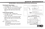
The DMP 780 Keypad Demonstrator Module is a portable module that connects to any
DMP Thinline, Icon Series, or 7800 Series Graphic Touchscreen keypad to demonstrate
keypad operation for sales and training presentations.
The module can demonstrate the Area, All/Perimeter, or Home/Sleep/Away systems and
can simulate arming and disarming. The 780 Demo also provides access to the following
User Menu options: ALARM SILENCE, SENSOR RESET, ARMED AREAS, ZONE MONITOR,
and USER CODES.
Compatibility
• Thinline keypad
• Icon Series keypad
• 7800 Series Graphic Touchscreen
keypad
Included Items
• One 780 Module (base and cover)
• One 9 V Battery
• One DC Power Supply
• Hardware pack
ABOUT THE 780

2 780 Installation and Programming Guide | Digital Monitoring Products, Inc.
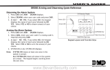
780 FEATURES
Figure 1: Product Features
699 DMP Desk Stand
780 Demo Module
Thinline Keypad
DC Power Supply Connection
4-Wire Harness from Keypad
to 780 Module J2 or J8 Connector
A
B
C
D
E
A
B
C
D
E

Digital Monitoring Products, Inc. | 780 Installation and Programming Guide 3
INSTALL THE 780
Mount the Demo Module
The 780 can be permanently mounted to the lower section of any Model 699 DMP
Keypad Desk Stand.
Use the included adhesive foam or screws to attach the demo module to the desk
stand base.
The mounting location is shown in Figure 1.
1

4 780 Installation and Programming Guide | Digital Monitoring Products, Inc.
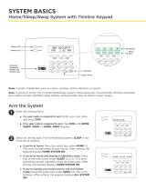
Power Up to Demo Module
Battery Operation for Thinline or Icon Series
Use the following steps to install and activate 9 VDC Battery operation.
1. Squeeze the top and bottom of the 780 module case to remove the cover.
2. Install the 9 VDC battery in the battery compartment. Observe polarity when
installing the battery. See Figure 2.
3. Install the jumper on the battery header (Battery ON/OFF) to enable battery
operation. See Figure 2.
DC Power Supply Operation
Use the following steps to connect the DC power supply.
1. Plug the barrel connector into the DC power supply plug on the side of the
780 module. See Figure 2.
2. Plug the DC Power Supply into a 110 Volt AC outlet.
Note: DC power supply operation automatically overrides and internally
disconnects battery operation. The DC Power Supply is required for use with the
7800 Series Graphic Touchscreen keypad.
2

Digital Monitoring Products, Inc. | 780 Installation and Programming Guide 5
DC
Power
Supply
To Keypad
To Keypad
PWR
BATTERY
ON/OFF
RED
BLK
RED
BLK
DC Power Supply Plug
Battery
Compartment
MODEL
780
Figure 2: 780 PCB Layout and Power Options

6 780 Installation and Programming Guide | Digital Monitoring Products, Inc.
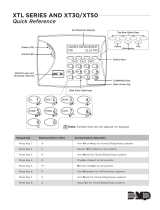
Connect the Keypad
3
RED
BLK
RED
BLK
4-pin Header Locations
Main Optional
Figure 3: Keypad Connectors
Icon or Thinline Keypad
1. Remove the keypad cover, with circuit board and components attached, from the
keypad base.
2. Align the keypad base to the four keypad mounting holes on the 699 Deskstand.
3. Insert the screws through the keypad base and deskstand.
4. Use a Phillips-head screwdriver to tighten the four screws into place.
5. Run the 4-wire harness through the opening in the deskstand and keypad base.
6. Observe wire colors and plug one end of the 4-wire harness into the back of
the keypad.
7. Connect the opposite end of the 4-wire harness to the 4-wire header in the top
of the 780 housing. When using a second keypad, connect the second 4-wire
harness to the 4-wire header.
Note: It is not necessary to remove the 780 module cover to complete the
keypad connection.

Digital Monitoring Products, Inc. | 780 Installation and Programming Guide 7
7800 Series Keypad
1. Remove the 7800 keypad cover, with circuit board and components attached,
from the keypad base.
2. Align the keypad base to the four keypad mounting holes on the 699 Deskstand.
3. Insert the screws through the keypad base and deskstand.
4. Use a Phillips head screwdriver to tighten the four screws into place.
5. Run the 4-wire harness through the opening in the deskstand and keypad base.
6. Plug the terminal end onto the right edge of the 12-pin header in the back of
the keypad.
7. Snap the keypad cover onto the base.
8. Connect the opposite end of the 4-wire harness to the 4-wire header in the
top of the 780 housing.
Black Ground
Green Receive Data
Yellow Send Data
Red Keypad Power
7800 Back
J5 J4
Y/W
R
G/W
V
Figure 4: 7800 Keypad Connectors

8 780 Installation and Programming Guide | Digital Monitoring Products, Inc.
Keypad Address
Set the keypad address to 01. To change the current address,
press any Select key and then enter the new address. When
using two keypads, set both keypads to address 01.
Keypad Mode
Set the keypad to Supervised. To change the current setting,
press the Select key under SUP or UNSUP to display an
asterisk and enable the selected mode. When using two
keypads select Unsupervised operation for the second keypad.
CURRENT KEYPAD
ADDRESS: 01
KEYPAD MODE:
*SUP UNSUP
PROGRAM KEYPADS FOR DEMONSTRATIONS
Icon Series Keypad
The Icon Series keypad does not need to be programmed for address or supervision.
Thinline™ Keypad
Access the Installer Options Menu through the User Options function. Hold down the Back
Arrow and CMD keys for two seconds to display SET BRIGHTNESS. Enter the code 3577
(INST) and press CMD. Select KPD OPT. Press the CMD key to scroll through the menu
and press any Select key when the desired option displays. Set the following options as
described to enable 780 operation.
When you complete keypad programming, press the CMD key once to return to the
Installer Options screen. Select STOP to exit the Installer Options function.

Digital Monitoring Products, Inc. | 780 Installation and Programming Guide 9
Keypad Address
Set the keypad address to 01. To change the current address,
press the address and enter the new address. When using two
keypads, set both keypads to address 01.
Keypad Mode
Set the keypad to Supervised. To change the current setting,
press SUP or UNSUP to display an asterisk and enable the
selected mode. When using two keypads select Unsupervised
operation for the second keypad.
CURRENT KEYPAD
ADDRESS: 01
KEYPAD MODE:
*SUP UNSUP
7800 Keypad
Access the Options screen on the Carousel menu and press Installer Options. Enter the
code 3577 (INST) and press CMD. Select KPD OPT. Press CMD to scroll through the menu
and press the desired option when displayed. Set the following options as described to
enable 780 operation.
When you complete keypad programming, press CMD once to return to the Installer
Options screen. Select STOP to exit the Installer Options function.
See the Icon Series Keypad Installation Guide (LT-0953), Thinline Keypad Installation
Guide (LT-0883), or 7800 Series Keypad Install Guide (LT-1162) for the complete keypad
programming menu.

10 780 Installation and Programming Guide | Digital Monitoring Products, Inc.
PROGRAM KEYPADS FOR
FIRE PANIC DEMONSTRATIONS
Icon Series Keypad
Access the Installer Options Menu from the User Options menu while displaying the
Software Version or Model Number. When either is displayed, enter the code 3577 (INST)
and press CMD.
Fire Key (F 1)
Use this option to configure the top two right Select keys as
2-button Fire keys. The far left position displays F (Fire) and
the far right position displays the fire key setting. To enable
the fire key operation press the number one key. This toggles
between one (1) and zero (0) on the display. Zero (0) disables
this option.

Digital Monitoring Products, Inc. | 780 Installation and Programming Guide 11
Arm Panic Keys
Use this option to configure the top row far right Select keys as
2-button Fire Panic keys. To enable or disable the panic keys,
press the Select key under the FI (Fire) display. Once the fire
panic is enabled, an asterisk displays next to the description.
See the keypad’s Installation Guide (LT-0883) for the complete
keypad programming menu.
ARM PANIC KEYS:
PN EM *FI
Thinline Keypad
Access the Installer Options Menu through the User Options function. Hold down the Back
Arrow and CMD keys for two seconds to display SET BRIGHTNESS. Enter the code 3577
(INST) and press CMD.
Arm Panic Keys
Use this option to configure the Panic Icons. To enable or
disable the Panic Icon, press the icon name FI (Fire). Once
the Panic Icon is enabled, an asterisk displays next to the
description and press CMD. The Panic Icon displays for the
user. See the 7800 Series Keypad Install Guide (LT-1162) for the
complete keypad programming menu.
ARM PANIC KEYS:
PN EM *FI
7800 Keypad
Access the Installer Options Menu through the User Options function. Press the Installer
Options Icon to display the Keypad screen. Enter the code 3577 (INST) and press CMD.
Press KPD OPT and then press CMD until ARM PANIC KEYS is displayed.

12 780 Installation and Programming Guide | Digital Monitoring Products, Inc.
Access the Options screen on the Carousel menu and press Installer Options. Enter the code
3577 (INST) and press CMD. Select KPD OPT. Press CMD to scroll through the menu. Press
the Carousel Z-Wave Items when displayed.
Use this option to select the Z-Wave options to be
displayed in the Carousel Menu on the main screen. Press
the item to select and a check-mark displays. Press again
to de-select. Items for the Carousel include Lights, Locks,
Thermostats, and Favorites.
PROGRAM THE GRAPHIC KEYPAD
FOR Z-WAVE DEMONSTRATIONS
CAROUSEL Z-WAVE ITEMS
TUE 5:35 PM
Lights
Doors
Thermostats
Favorites
CMD

Digital Monitoring Products, Inc. | 780 Installation and Programming Guide 13
PROGRAM AN ARMING SYSTEM FOR THE 780
Icon Series Keypad
Within the first 20 seconds of power-up, select All/Perimeter or Home/Sleep/Away arming
systems to demonstrate.
All/Perimeter
Press the ALL (1) button or the PERIM (6) button for 2 seconds
to select. All/Perimeter arming system.
Home/Sleep/Away
Press the HOME (3) button or the SLEEP (7) button for 2
seconds to select the Home/Sleep/Away arming system.
Note: If an arming system is not selected within the first
20 seconds or the CMD key is pressed, the 780 reverts to
the last arming system programmed for demonstration. If
the last arming system programmed was an Area system,
the Icon Series keypad displays bSY. Use a Thinline
keypad to change the arming system or power down and
power up the 780 to select All/Perimeter or Home/Sleep/
Away.

14 780 Installation and Programming Guide | Digital Monitoring Products, Inc.
Programmer
Enter 6653 at the status list to access the Programmer. Press
CMD. The currently selected arming system displays.
Arming System
To change the current system, press any Select key to display
the options. Press the Select key below the system to use,
Area, A/P, or H/A. Press CMD to display STOP and press any
Select key to end programming.
PROGRAMMER
ARMING SYSTEM
AREA A/P H/A
Thinline Keypad
Select Area, All/Perimeter, or Home/Sleep/Away arming systems to demonstrate.
Programmer
Access the keypad screen through the Carousel menu. Enter
6653 at the status list to access the Programmer. Press CMD.
The currently selected arming system displays.
Arming System
To change the current system, press ARMING SYSTEM to
display the options. Press the desired option to use, Area,
A/P, or H/A. Press CMD and press STOP to end programming.
PROGRAMMER
ARMING SYSTEM
AREA A/P H/A
7800 Keypad

Digital Monitoring Products, Inc. | 780 Installation and Programming Guide 15
7800 Keypad
For demonstration purposes, the Area, All/Perimeter, and Home/Sleep/Away arming
systems contain factory programmed areas.
AREA ARMING
All/Perimeter (All/Perim)
and Home/Sleep/Away (H S A)
1. Northwest Oce (includes the Front Door) Perimeter (includes the Front Door)
2. Manufacturing Interior
3. South Warehouse Bedrooms (H S A)
4. West Power Plant

16 780 Installation and Programming Guide | Digital Monitoring Products, Inc.
780 DEMONSTRATION
Keypad Operation
The 780 Demo module simulates the keypad User Menu available to customers in actual
installations. Use the following sections to demonstrate keypad setup and operation. Prior
to demonstrating operation, make sure your demo keypad is set as follows:
• 7800/Thinline: Set to Address 1 and accepts 4-digit user codes from the keypad.
• Icon: Does not need to be programmed for address, supervision, or 4-digit user codes.
/