Page is loading ...

LT-2209 20303
HOW-TO GUIDE:
ECP PASSTHRU
© 2020

COM SERIES HOW-TO GUIDE: ECP PASSTHRU | DIGITAL MONITORING PRODUCTS 2
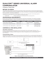
ECP PASSTHRU OVERVIEW
CellCom and DualCom Universal Communicators enable you to take over and manage ECP panels with
connection to the ECP Bus. This feature is called ECP Passthru.
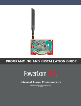
Required Materials
The following software and hardware components are required to perform system takeovers:
• Compatible Honeywell VISTA panel (refer to “VISTA Panel Compatibility”)
• CellCom or DualCom with firmware Version 202 or higher
• Programming keypad
• Model 330 or Model 330-24V programming cable
• Cat 5 Ethernet cable (only when using network)
• 18-22 AWG unshielded wire (RYGB)
• Remote Link Version 2.02 or higher
+DC- Z1 Z2 Z3
G
T R
+Z4-
O1 O2
B
C
PROG
B
R
RESETLOAD
D
H
A
G
E
+DC- Z1 Z2 Z3
G
T
R
+Z4-
O1 O2
F
I
CellCom or DualCom
DC Power
Zones 1 - 4
Tip 1
Output 1
Output 2
Ring 1
ETHERNET
J
A
B
C
D
E
F
G
H
Mounting Holes
Cellular Antenna
SMA Connector
Cell Modem
Tamper
Programming Connection
Terminal Block
Load and Reset Buttons
I
Power and Armed LEDs
J
Ethernet (DualCom only)
Figure 1: CellCom and DualCom Components

COM SERIES HOW-TO GUIDE: ECP PASSTHRU | DIGITAL MONITORING PRODUCTS 3
WIRE THE COMMUNICATOR
The communicator can be connected to the ECP Bus of a Honeywell panel. See Table 1 and Figure 2 for the
necessary wiring connections.
Caution: Remove all AC and battery power from the panels before wiring.
1. Attach the antenna to the SMA connector. Refer to Figure 1.
2. Connect system batteries as needed, then connect the panels
to an appropriate power source.
3. Connect a programming keypad to the communicator.
a. For 12VDC applications, connect the keypad to
the communicator PROG header with a Model330
programming harness.
b. For 24VDC applications, connect the keypad to the
communicator PROG header with a Model330-24V
programming harness with an in-line resistor.
4. After programming is complete, remove the keypad and replace the housing cover on the mounted base.
Note: Address 1is reserved by the system for programming keypads.
MOUNT THE COMMUNICATOR
It is not necessary to remove the PCB from the housing when installing the communicator. The
communicator should be mounted to a wall using the included #6 screws in the mounting holes. Refer
to Figure 1 for mounting hole locations. Mount the communicator in a secure, dry place to protect it from
tampering and weather damage. If using a 685 Series Conduit Backbox, refer to the 685 Installation Sheet
(LT-1431) for mounting instructions.
+DC- Z1 Z2 Z3
G
T
R
+Z4-
O1 O2
CellCom or DualCom
1 2 3 4 5 6 7 8 9 10 11 12 13 14 15 16 17 18 19
20
21 22 23 24
25
+ +–
HI
HI
HI
LO
LO
LO
LO
HI
HI
LO
LO
HI
HI
LO
LO
HI
TIP
(BROWN)
RING
(GRAY)
TIP
(GREEN)
RING
(RED)
+
-
BLACK
RED
SYNC
COM
DATA
(USE SA4120XM-1
CABLE)
1 2 3 4 5 6 7 8
OUT 17
+12 AUX
GND
OUT 18
VISTA 20P ONLY
VISTA-20P
From DC+
From DC–
From Z4+
From Z4-
To Data In (6)
To Data Out (7)
To Negative (4)
To Positive (5)
RED
BLACK
GREEN
YELLOW
RED
BLACK
GREEN
YELLOW
RED
BLACK
GREEN
YELLOW
Figure 2: ECP Wiring
Communicator to ECP Wiring
Communicator Honeywell ECP Bus
+DC Keypad Power
-DC Keypad GND
Z4+ Data Out
Z4- Data In
Table 1: ECP Wiring

COM SERIES HOW-TO GUIDE: ECP PASSTHRU | DIGITAL MONITORING PRODUCTS 4
PROGRAM THE COMMUNICATOR
Program Vista Keypad Device Address 20
1. Power down and then power up the Honeywell panel.
2. Within 1 minute of powering up the Honeywell panel, simultaneously press and hold the # and *
buttons on the keypad.
3. The keypad displays INSTALLER CODE. Enter the installer code (default is 4112), followed by
800.
4. Enter *193, then enter 1 0.
5. To save and exit programming, enter *99.
Change Keypad Input to ECP
1. Press and release the communicator Reset button.
2. At the communicator keypad, enter 6653 (PROG) and press CMD.
3. Advance to SYSTEM OPTIONS, then press any select key or area to enter the menu.
4. Advance to KYPD INPUT, then press any select key or area.
5. Press the third select key or area to select ECP.
6. To save programming, advance to STOP and press any select key or area.
Auto-Configure the ECP Panel
Universal Communicators with firmware Version 202 and higher enable installers to automatically
configure ECP panels for Passthru communication. Refer to Table 2 for programming messages and
troubleshooting steps.
1. Ensure the ECP panel IP address is set as default.
2. At the communicator keypad, enter 2313 (DIAG) and press CMD.
3. Advance to ECP SETUP and press any select key or area.
4. At ECP SETUP VISTA 128? If the panel is a VISTA 128, select YES. If the panel is a different model,
select NO.
5. At INST CODE, enter the ECP panel installer code and press CMD.
6. After configuration is finished, the keypad advances to GET ZONES. Press any select key or area.
As the communicator retrieves zones from the ECP panel, the number of zones is displayed and
incremented as ZONE CT (zone count).
1
2
3
This section assumes that you’ve already programmed basic communicator settings. For more complete
information about programming, refer to the CellCom Installation Guide (LT-1817) or the DualCom Installation
Guide (LT-1859).
To advance through the programming menu, press CMD. To go back, press the Back Arrow key. To enter a
menu, press any select key or area. To select an option, press the select key or area under that option.

COM SERIES HOW-TO GUIDE: ECP PASSTHRU | DIGITAL MONITORING PRODUCTS 5
ADDITIONAL INFORMATION
Remote Programming
VISTA panels can be remotely programmed with Remote Link and Honeywell’s Compass® software. For
information about configuring Compass to work with Remote Link on a passthru system, refer to Remote
Link How-To Guide: ECP Passthru Compass Setup (LT-1944).
Virtual Keypad
Virtual Keypad enables users to manage their systems remotely, including arming, disarming, viewing zone
status, bypassing zones, view history, manage users, and more.
Table 2: Programming Messages and Troubleshooting
Message Meaning Next Steps
PROGRAMMING
The communicator is attempting to
configure ECP panel programming
settings for ECP Passthru.
Wait for the configuration attempt to
complete. Afterward, a programming status
message is displayed (success, fail, or busy).
PROGRAM SUCCESS
The ECP panel has been successfully
configured.
Finish configuration at GET ZONES.
PROGRAM FAIL
The ECP panel could not be
programmed.
Check wiring connections and
communication settings, then retry
programming.
BUS IS BUSY
The ECP panel could not be
programmed due to high ECP bus
traffic.
Wait and retry programming or reduce
traffic on the ECP bus, then retry
programming.

Designed, engineered,
and manufactured in
Springfield, Missouri
INTRUSION • FIRE • ACCESS • NETWORKS
2500 North Partnership Boulevard
Springfield, Missouri 65803-8877
800.641.4282 | dmp.com
VISTA Panel Compatibility
Panel Type ECP
Remote
User Management
Remote
Arming/Disarming
Remote
Zone Status
Compatible with
Compass
VISTA-10SE Rev 15 or higher No No No No
VISTA-10P Yes Yes Yes Yes
Firmware version
2.0 or higher
VISTA-15 Yes No No No No
VISTA-15P Yes Yes Yes Yes
Firmware version
5.2 or higher
VISTA-20SE Rev 12 or higher No No No No
VISTA-20P Yes Yes Yes Yes
Firmware version
5.2 or higer
VISTA-20PI Yes Yes Yes Yes
Firmware version
5.0 or higher
VISTA-21iP Ye s Ye s Ye s Ye s Yes
VISTA-21iPLTE Yes Yes Yes Yes Yes
Note: Panels must be programmed as Stay/Away for remote arming and disarming (No
Partitions).
Vista 32, 40, 50, 128, 250 are not compatible with ECP Virtual Keypad and eSuite.
/