Page is loading ...

503INT INTERNATIONAL POWER SUPPLY
Installation Guide
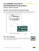
Figure 1: 503INT International
Power Supply
L N
+ BAT -
+ BAT -
AC TRBL | BAT TRBL FROM PANEL |
1MOUNT THE ENCLOSURE
Mount the metal enclosure on a solid, flat, vertical, and
secure surface such as dry wall or masonry using four #8 1/2”
panhead screws. This is to protect the unit from damage due
to tampering or the elements. See Figure 4 for the mounting
orientation.
The 503INT International Power
Supply is a regulated, power
limited, switching power supply
rated for a maximum output of
15VDC at 2.7 Amps. The 503INT is
a supervised power supply.
The 503INT includes battery leads
and is offered pre-mounted in an
enclosure with wall and enclosure
door tampers or as a separate
PCB.
The 503INT also provides
connections for 230 VAC input,
standby battery input, DC output,
AC and battery trouble relays,
data bus input/output, tamper
input, and keypad programming
connection.
Compatibility
All DMP International
control panels.
What is Included?
• 503INT International Power
Supply
• High Voltage Shield
• Hardware Pack
DESCRIPTION 2MOUNT THE 503INT PCB
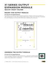
Mount the 503INT PCB in the metal enclosure using the
provided hardware. See Figure2 for mounting hole locations.
1. Place the PCB inside the metal enclosure.
2. Install the three standos in the stando holes.
3. Install the two screws in the mounting holes.
AC power connection should only be installed by a qualified
electrician. Before turning on the 503INT's AC power, make
sure all electrical covers are in place.
Caution: Do not apply power to the 503INT until all wiring
connections are made and free of direct shorts or open
circuits.
1. Connect the AC power input to an unswitched 230 VAC
50 Hz power source with at least 1.5 Amps of available
current.
2. Connect the AC power wires
to the terminal block. See
Figure 3.
• Connect the brown wire to the
L terminal
• Connect the blue wire to the
Nterminal
• Connect the green and yellow
wire to the (ground) stud using a
ring terminal.
J1
AC
L N
Blue Wire
Brown Wire
Green and
Yellow Wire
To ground
Figure 3: AC Terminals
and Wires
3WIRE AC CONNECTIONS
Figure 2: Mounting Hole Locations
L N + BAT - + BAT - AC TRBL | BAT TRBL FROM PANEL |
Stando
Hole
Stando
Holes
Mounting Holes

2 503INT POWER SUPPLY INSTALLATION GUIDE | DIGITAL MONITORING PRODUCTS
Figure 5: Single Battery Connection
318EXT Harness
Battery
J7
+ -
+ -
AC TRBL BAT TRBL
J6
J1
AC
FROM PANEL TO DEVICES
R Y G B R Y G B
J9
NC C NO NC C NO
J10
J8
318EXT Harness
Battery 2
318R Dual
Battery Harness
PTC
Battery 1
J7
+ -
AC TRBL BAT TRBL
J6
J1
AC
FROM PANEL TO DEVICES
R Y G B R Y G B
J9
NC C NO NC C NO
J10
J8
Figure 6: Dual Battery Connection
J11
+ DC -
AC TRBL BAT TRBL
J6
J7J1
NAC Module
AC
+ BAT -
RED
BLK
FROM PANEL TO DEVICES
R Y G B R Y G B
L N
J4
J9
J3
NC C NONC C NO
J10
J8
NAC
Module
To Tamper Header
Tamper
Header
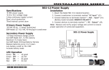
KYPD LX Bus
AC Terminal
High Voltage Shield
Power
Limited/Class 2
wire routing
through conduit
knockouts.
PROG
AC/battery
output relay
connections
Battery Wires
(included)
Shaded area for either one or two batteries.
Tamper
Switch
Stud for
incoming
ground
wire
Mounting Hole Mounting Hole
Figure 4: 503INT Wiring Diagram

503INT POWER SUPPLY INSTALLATION GUIDE | DIGITAL MONITORING PRODUCTS 3
The AC and battery trouble relay connections are form C contacts
rated at 30 VDC. Form C contacts are single pole, double throw (SPDT)
relays that provide one common (C), one normally open (NO), and one
normally closed (NC) connection. When AC or battery trouble occurs,
the relay contacts switch from normally closed to normally open.
1. Connect the AC TRBL supervisory relay output terminals
marked NC and C to the control panel. See Figure 7.
2. Connect the BATT TRBL supervisory relay output terminals
marked NC and C to the panel.
AC TRBL
J6
NC C NO NC C NO
BAT TRBL
Figure 7: AC and Battery Trouble
Relay Connections
5WIRE TROUBLE RELAY CONNECTIONS
6WIRE DC OUTPUT CONNECTIONS
Connect the device that requires power to the power output terminal
marked + DC - and observe polarity. See Figure 8.
J11
+ DC -
Figure 8: DC Output
Connections
Connect batteries to the 503INT to ensure there will be back-up power if AC power fails. If using
two or more batteries, use a 318 or 318R (ring terminal) dual battery harness. See Figures 5 and 6.
1. Observing polarity, connect the black battery lead to the negative battery terminal.
2. Connect the red battery lead to the positive battery terminal.
Note: The battery input has built-in protection against defective batteries. Only use
sealed lead-acid batteries and replace them every 3–5 years.
Caution: Explosion may occur if batteries are replaced with incorrect battery type.
4WIRE BATTERY CONNECTIONS
7WIRE DATA BUS CONNECTIONS
The 503INT communicates with the panel using the FROM PANEL
terminals. Status changes such as battery or tamper trouble are sent to
the panel using the DC output connection. The TO DEVICES terminals
provide power from the 503INT and pass data to other devices.
1. Connect the control panel's keypad or LX bus to the FROM
PANEL terminals on the 503INT. See Figure 9.
2. To send data out to keypads or zone expanders, connect to the
TO DEVICES terminals on the 503INT.
3. Set the KYPD LX Bus expansion jumper above the terminals to
the appropriate bus type.
FROM PANEL TO DEVICES
R Y G B R Y G B
J9 J10
Blue
Green
Yellow
Red
Blue
Green
Yellow
Red
KYPD LX Bus
J3
Figure 9: Data Bus
Connections and
KYPDLXBus Expansion
Jumper

4 503INT POWER SUPPLY INSTALLATION GUIDE | DIGITAL MONITORING PRODUCTS
10
PROGRAM THE POWER SUPPLY
After mounting the enclosure and connecting the wiring for the 503INT, use a DMP keypad to
program the power supply.
1. Connect a DMP keypad to the PROG header.
Caution: The connector is keyed with the red wire to the bottom and the black wire
towards the top. Make sure that the harness is connected correctly to the keypad
and the PROG connection on the power supply.
2. After the keypad is connected, the software version and date code display. Press CMD.
3. The BUS TYPE: screen displays. Press the left select key or area to choose KEYPAD, or
press the right select key or area to choose LX. Press CMD.
4. When the DEVICE NUMBER: screen displays, enter a device number between 01 and 16
for the Keypad Bus or 01 and 99 for the LX Bus. Press CMD.
5. When the REMOVE KEYPAD screen displays, it is safe to remove the keypad.
9CONNECT THE TAMPER SWITCH
The tamper switch in the 503INT enclosure helps to protect
the power supply from damage by generating an alert when
the enclosure is tampered with. The tamper switch creates a
normally closed circuit that opens when faulted.
1. Locate the TAMPER header. See Figure 11.
2. Connect a tamper harness to the tamper header.
3. Connect the tamper harness flying leads in series with
the enclosure’s tamper switch.
4. Using the included screws, attach the tamper switch to
the tamper bracket.
5. Place the tamper bracket through the slot in the back of
the enclosure and attach it to the wall.
J11
+ DC -
AC TRBL BAT TRBL
J6
J7J1
NAC Module
AC
+ BAT -
RED
BLK
FROM PANEL TO DEVICES
R Y G B R Y G B
L N
J4
J9
J3
NC C NONC C NO
J10
J8
NAC
Module
To Tamper Header
Tamper
Header
KYPD LX Bus
AC Terminal
High Voltage Shield
Power
Limited/Class 2
wire routing
through conduit
knockouts.
PROG
AC/battery
output relay
connections
Battery Wires
(included)
Shaded area for either one or two batteries.
Tamper
Switch
Stud for
incoming
ground
wire
Mounting Hole Mounting Hole
Figure 11: Tamper Switch
Connection
12
ATTACH THE HIGH VOLTAGE SHIELD
Attach the High Voltage Shield to the PCB to prevent electrical shock. See Figure4 for shield
placement.
1. Remove the protective covering from the High Voltage Shield.
2. Install the shield onto the standos.
3. Secure the shield with the included screws.
8CONNECT THE GROUND STRAP
1. Using the included lock washer and nyloc nut, connect
one end of the ground strap to the enclosure. See
Figure10 for location.
2. Connect the other end of the ground strap to the
cabinet door.
Figure 10: Ground Strap
11POWER THE 503INT
Make sure all wiring is terminated before powering the 503INT. Measure and verify the output
voltage before connecting a device to the power output terminal. This ensures that the
equipment operates correctly.

503INT POWER SUPPLY INSTALLATION GUIDE | DIGITAL MONITORING PRODUCTS 5
Table 1: Zone States
ZONE NUMBER SHORT TYPE DESCRIPTION
1 AC Power Fault No power (AC = 0V)
2 Output Trouble The 503INT tamper was tripped or
battery charger faults were detected
3 Battery Trouble Battery voltage is 11.9 V or less
4 Temperature Fault Temperature has exceeded 125 °C
ADDITIONAL INFORMATION
The table below represents the dierent states of zones 1-4 and describes what the shorted state of a zone
indicates.
13PROGRAM THE PANEL
The 503INT uses the first four zones of the device address to report status changes to the
panel.
1. Enter 6653 (PROG) and press CMD for XR150INT/XR550INT Series panels or enter 665
and press CMD for XT30INT/XT50INT Series panels to access the PROGRAMMER menu. If
programming an LX device, go to step5.
2. Press CMD until DEVICE SETUP displays.
3. Program the appropriate DEVICE NO:.
4. Select EXP (expander) as the DEVICE TYPE.
5. Navigate to ZONE INFORMATION and press any select key or area.
6. Enter the ZONE NO: and select A1 as the ZONE TYPE.
7. Press CMD until NEXT ZONE? displays and select NO.
8. Press CMD until DISARMED SHORT displays and then press CMD again to display MSG:.
9. Press any select key or area and select T (trouble) as the message type.
10. Press CMD until ARMED SHORT displays and then press CMD again to display MSG:.
11. Press any select key or area and select T (trouble) as the message type.
12. Press CMD until STOP displays. Press any select key or area to save programming.
Note: A Sensor Reset is required to clear trouble messages from the keypad status
list.
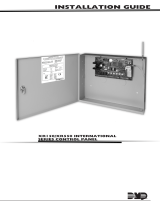
Replace the Fuse
1. Pull the fuse off of the 503INT PCB.
2. Line up the two pegs on the new fuse and insert the fuse into the two holes on
the 503INT PCB. See Figure 12.
L N
+ BAT - + BAT - AC TRBL | BAT TRBL FROM PANEL |
Fuse
Figure 12: Fuse
Location

Designed, engineered, and
manufactured in Springfield, MO
using U.S. and global components.
LT-1610INT 19175
INTRUSION • FIRE • ACCESS • NETWORKS
2500 North Partnership Boulevard
Springfield, Missouri 65803-8877
417.831.9362 | DMP.com
503INT INTERNATIONAL
POWER SUPPLY
Specifications
Voltage Input 230 VAC at 1.5 Amps Unswitched
Voltage Output 15 VDC at 2.7 Amps Max.
Secondary (Battery) Power 2 Amps Max.
Enclosure:
Material: 18-gauge, cold rolled steel
Color: Gray
Dimensions: 17.5"W x 13.5"H x 3.5"D
Output Levels
Nominal DC Voltage: 13.8-14.3 VDC
Low Battery: 11.9 VDC
Battery Restore: 12.6 VDC
Battery Cut O: 9.5 VDC
Max. Battery
Charging Current: 2 Amps
Certifications
EN 50131-6 Power Supplies
EN 50130-4 EMC Product Family Standard: Immunity Requirements for
Components of Fire, Intruder and Social Alarm Systems
EN 61000-3-2 Limits - Limits for Harmonic Current Emissions (Equip.Input
Current up to and Including 16 Aper Phase) Includes A1 & A2
July 1, 2009
EN 61000-3-3 Limitation of Voltage Fluctuations & Flicker in Low-Voltage
Supply Systems for Equip. with Rated Current Less Than
or Equal to 16 Amps per Phase & Not Subject to Conditional
Connection
EN 61000-6-4 Generic Standards - Emission Standard for Industrial
Environments
IEC 60950-1 Information Technology Equipment
EN 50131-6 Compliance
The 503INT International Power Supply is a Type A power supply and has the following specifications in
compliance with EN 50131-6 certification.
Ratings
Grade: 3
Input: 230 VAC, 50 Hz, 1.5 Amps
Output Grade 2: 15 VDC, 2 Amps (Total combined +DC- and TO DEVICES)
Output Grade 3: 15 VDC, 1.9 Amps (Total combined +DC- and TO DEVICES)
Ripple Voltage: Maximum Ripple Voltage is less than 5% of OUTPUT Voltage
Operating Temp.: 0-49 C (32-120 F)
Relative Humidity: 80%
Weight: 1.7 Kg
Other Specifications
• The 503INT uses 12 V SLA batteries.
• The 503INT is capable of charging a maximum of 60 Ah of batteries to 80% in 24 hours.
• Low battery is indicated at 11.9 V.
• Deep discharge protection disconnects the battery at 9.5 V.
• Over voltage protection disconnects the output at 16.8 V.
• The AC power connection must be connected to a readily accessible disconnect circuit breaker rated for
a minimum of 5 Amps.
• Use solid core copper wire for all connections, 14 AWG or larger for AC supply connection (diameter
1.63mm, area 2.08 mm2).
• Operator access areas are not provided.
/