Page is loading ...


ii
TABLE OF CONTENTS
INTRODUCTION ................................................................................................................................................. 1
Hardware Overview ........................................................................................................................................ 1
Hardware Specifications................................................................................................................................. 2
CONNECTING THE DUALCOM S.................................................................................................................... 3
Serial Connection............................................................................................................................................ 3
TCP/IP Connection ......................................................................................................................................... 4
SERIAL INTERFACE SETUP............................................................................................................................ 6
Serial Interface Navigation ............................................................................................................................. 6
Outlet States & Settings ................................................................................................................................. 6
Turning an Outlet On/Off ........................................................................................................................... 7
Rebooting an Outlet ................................................................................................................................... 7
Editing the Properties of an Outlet ............................................................................................................ 7
Setting High/Low Currents and Grace Periods.................................................................................... 9
Enabling Cyber Breaker® the Virtual Circuit Breaker™ ..................................................................... 9
Temperature and Humidity Data & Settings ...............................................................................................10
Logs ...............................................................................................................................................................11
System Settings ............................................................................................................................................12
TIME/DATE Setup.................................................................................................................................... 13
NETWORK Setup..................................................................................................................................... 14
LOGGING Setup ...................................................................................................................................... 15
SNMP Setup .............................................................................................................................................16
GENERAL Setup...................................................................................................................................... 17
USER(S) Setup ........................................................................................................................................18
WEB INTERFACE SETUP...............................................................................................................................21
Outlet Tab......................................................................................................................................................22
Turning an Outlet On/Off .........................................................................................................................22
Rebooting an Outlet .................................................................................................................................23
Editing the Properties of an Outlet ..........................................................................................................23
Setting High/Low Currents and Grace Periods..................................................................................24
Enabling Cyber Breaker® the Virtual Circuit Breaker™ ................................................................... 25
Scheduling a Task.................................................................................................................................... 25
Temp/Hum Tab .............................................................................................................................................26
Logs Tab........................................................................................................................................................28
Users Tab ......................................................................................................................................................29
Edit/Add Users..........................................................................................................................................29
Setup Tab ......................................................................................................................................................31
TIME/DATE Setup.................................................................................................................................... 32
NTP ...........................................................................................................................................................32
NETWORK Setup..................................................................................................................................... 33
LOGGING Setup ...................................................................................................................................... 33
SNMP Setup .............................................................................................................................................35
GENERAL Setup...................................................................................................................................... 36
System Information .................................................................................................................................. 37
FAQs .................................................................................................................................................................. 39
Mounting Diagram for Vertical Dualcom S .................................................................................................40
Temperature/Humidity Sensor ......................................................................................................................41
RADIO FREQUENCY INTERFERENCE ........................................................................................................42

iii
CE certificate will go on this page.

iv
Symbols
The following symbols are used as references and can be found on the Dualcom S:
Caution: There is a risk of equipment damage and or
personal injury. Follow the instructions.
Caution: Hazardous voltages are present. To
reduce the risk of electrical shock and possible injury,
please follow the instructions.
TCP/IP (Web, Telnet, and SNMP): 10BaseT
ethernet port.
Serial Port: Direct RS232 connection to a laptop or
desktop PC.

v
Rack Mounting Instructions
When mounting the PDU to a network/data rack, please take note of the following safety and
precautionary guidelines:
A) Please only use the provided mounting hardware.
B) Elevated Operating Ambient - If installed in a closed or multi-unit rack assembly, the
operating ambient temperature of the rack environment may be greater than room
ambient. Therefore, consideration should be given to installing the equipment in an
environment compatible with the maximum ambient temperature specified by the
manufacturer.
C) Reduced Air Flow – Equipment should be installed so that the amount of air flow
required for safe operation of the equipment is not compromised.
D) Mechanical Loading – Equipment should be mounted so that a hazardous condition is
not achieved due to uneven mechanical loading.
E) Circuit Overloading - Consideration should be given to the connection of the equipment
to the supply circuit and to the effect that overloading of the circuits might have on
overcurrent protection and supply wiring. Appropriate consideration of equipment
nameplate ratings should be used when addressing this concern.
F) Reliable Earthing - Reliable earthing of rack-mounted equipment should be maintained.
Particular attention should be given to supply connections other than direct connections
to the branch circuit (e.g., use of power strips).
G) For pluggable equipment, the socket outlet shall be installed near the equipment and
shall be easily accessible. A suitably rated, listed branch circuit breaker shall be
provided as part of the building installation.

vi
Safety Instructions
FOR YOUR SAFETY, OBSERVE THE FOLLOWING PRECAUTIONS WHEN SETTING UP
YOUR EQUIPMENT:
UPON INITIAL INSPECTION, IF THE UNIT APPEARS TO BE DAMAGED,
DO NOT INSTALL. CONTACT CYBER SWITCHING IMMEDIATELY.
FOLLOW ALL CAUTIONS AND INSTRUCTIONS MARKED ON THE
EQUIPMENT.
A SUITABLY RATED, LISTED BRANCH CIRCUIT BREAKER SHALL BE
PROVIDED AS PART OF THE BUILDING INSTALLATION.
ENSURE THAT THE VOLTAGE AND FREQUENCY OF THE POWER
SOURCE MATCH THE VOLTAGE AND FREQUENCY ON THE CYBER
SWITCHING EQUIPMENT ELECTRICAL RATING LABEL.
NEVER PLACE FOREIGN OBJECTS OF ANY KIND THROUGH OPENINGS
IN THE EQUIPMENT. CONDUCTIVE FOREIGN OBJECTS WILL PRODUCE
A SHORT CIRCUIT THAT CAN CAUSE FIRE, EQUIPMENT DAMAGE,
AND/OR ELECTRICAL SHOCK.
WHEN INSTALLING THE UNIT INTO A RACK, DO NOT BLOCK
VENTILATION OPENINGS OF THE UNIT.
THE SOCKET OUTLET SHALL BE INSTALLED NEAR THE EQUIPMENT
AND BE EASILY ACCESSIBLE.
DUAL SOURCE UNITS REQUIRE SEPARATE CIRCUITS TO INDIVIDUAL
BRANCH CIRCUIT PROTECTION.
MULTIPLE POWER SOURCES REQUIRE THAT ALL SOURCES BE
DISCONNECTED PRIOR TO SERVICING.
WARNING - TO REDUCE THE RISK OF FIRE OR ELECTRIC SHOCK,
INSTALL IN A CONTROLLED ENVIRONMENT RELATIVELY FREE OF
CONTAMINANTS.

vii
Notes

1
INTRODUCTION
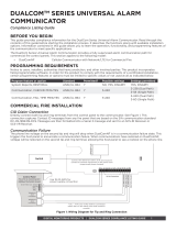
Hardware Overview
(Horizontal Unit Shown)
1: Indicates the total number of amps being used
2: Green LED indicates outlet is energized; red LED indicates Cyber Breaker® has
tripped. Amber LED indicates outlet current is outside of the high or low limit setting.
3: Temperature/humidity sensor port (RJ25) – optional
4: RS232 Serial port (RJ45)
5: Ethernet port (RJ45)
6: AC inlet receptacles (C-20 shown)
7: AC outlets (5-20R shown)

2
Hardware Specifications
Model
Circuit
Banks
Total Continuous
Input/Output
Receptacle Type
Dualcom S 440i
2
16 A per bank
C19
Dualcom S 460L5
2
24 A per bank
L5-30
Dualcom S 460L6
2
24 A per bank
L6-30
Dualcom S 816i-EU
1
16 A
C13
Dualcom S 820
1
16 A
5-20
Dualcom S 830i
2
12 A per bank
C13
Dualcom S 832i-EU
2
16 A per bank
C13
Dualcom S 840
2
16 A per bank
5-20
Dualcom S 840i
2
16 A per bank
C19
Dualcom S 1620V
1
16 A
5-20
Dualcom S 1620VATX
1
16 A
5-20
Dualcom S 1630ViCB
2
16 A per bank
C13
Dualcom S 1630ViCBMO
2
16 A per bank
C13/C19
Dualcom S 1630ViCBMOMV*
2
16 A per bank
C13/C19
Dualcom S 1632ViCB
2
16 A per bank
C13
Dualcom S 1632ViCB-EU
2
32 A / 20 A per bank
C13
Dualcom S 1632ViCBMO
2
16 A per bank
C13/C19
Dualcom S 1632ViCBMO-EU
2
16 A per bank
C13/C19
Dualcom S 1640V
2
16 A per bank
5-20
Operating temperature 0 – 45°C
Vertical unit dimensions 1.75W x 2.75D x 65.0H (excluding mounting hardware)
Horizontal unit dimensions 17.0W x 10.3D x 1.75H (19.0W with mounting hardware)
*120V C13 and 208V C19 configuration.

3
CONNECTING THE DUALCOM S
Perform the following to attach the Dualcom S unit using a serial or TCP/IP
connection.
Serial Connection
1) Attach the unit to a COM port on your computer using the supplied DB9
to RJ45 adapter and the supplied green inverse cable.
2) Setup a terminal program using the following default settings:
• 9600 baud
• 8 data bits; no parity
• 1 stop bit
• no flow control
3) Establish a connection and log on using admin as the User Name and
password as the Password.
Note: It is recommended that you periodically change the password to
prevent unauthorized access to the Dualcom S.
Chapter
1

4
The Dualcom S main menu appears:
Note: At the bottom of most screens are help areas that provide information on
how to navigate and edit settings within the serial/telnet interface.
TCP/IP Connection
The Dualcom S administration can be performed either by Telnet or through a
web browser. The Telnet session uses a VT100/ANSI terminal type, and is
identical in look and feel to the Serial interface.
The web interface utilizes MD5 security. Some older versions of web browsers
may have problems with the higher level of security required for MD5
authentication. If problems with logging in are experienced, please download
the latest version or update the browser.
The following describes how to connect to the Dualcom S using a web browser:
1) Note the MAC address from the label on the Dualcom S unit.
2) Attach the unit to a network with a DHCP server using the Ethernet port
on the front of the Dualcom S unit. Power up unit and allow it to pick up
an IP address.
3) Once an IP address is selected, find the address in the DHCP table of
your DHCP server that corresponds to the unit’s MAC address.
4) In your browser, enter the IP address assigned by your DHCP server.
5) Log on using admin and password as the User Name and Password
(once other user accounts have been created, they can be used here as
well).

5
Note: It is recommended that you periodically change the password to
prevent unauthorized access to the Dualcom S.
The following screen appears:

6
SERIAL INTERFACE SETUP
Once communication with the Dualcom S is configured as described in the
Serial Connection section, the serial interface is ready for use.
Serial Interface Navigation
There are two ways to navigate and select items using a serial connection:
• Press a number key (if applicable)
• Use the arrow keys to highlight an item, and hit Enter to select it.
Once an item has been selected, you can edit it by pressing Backspace to
erase existing values, and the number/letter keys to enter new ones. You can
also use Backspace to return to a previous screen.
Outlet States & Settings
From the main menu, type 1 to select Outlet States & Settings.
Chapter
2

7
The following screen appears:
There are four things that can be done from this screen:
• Turn on/off a specific outlet
• Reboot an outlet
• Select an outlet to edit its properties
• Save the current on/off state for each outlet as the power on
state
Turning an Outlet On/Off
To turn an individual outlet on or off, navigate to the desired outlet and press +
to turn it on, or – to turn it off. To turn all outlets on or off at once, navigate to
ALL OUTLETS and press + or –.
Note: When the Dualcom S is powered up, all outlets are ON by default. To
change an outlet so that it will be off when the Dualcom S is powered up, turn
off all desired outlets as described above and press 0. Similarly, turn on an
outlet that is turned off and press 0 to have it be on whenever the Dualcom S
powers up.
Rebooting an Outlet
To reboot an individual outlet, navigate to the desired outlet and press R/r. The
outlet will turn off after the reboot delay timer expires and then turn back on
once the reboot off timer terminates. To reboot all outlets at once, navigate to
ALL OUTLETS and press R/r.
Note: The settings for both the reboot delay timer and reboot off timer can be
changed in the properties of each individual outlet (see Editing the Properties
of an Outlet). The default for both timers is five seconds.
Editing the Properties of an Outlet
To edit the properties of an outlet, navigate to the desired outlet and press
Enter. The following screen appears:

8
There are ten outlet settings that can be changed:
• Outlet Label
• Reboot delay (sec.)
• Reboot off (sec.)
• Enable Low Current Alerts
• Low Current (Amps)
• Low Grace Period (ms)
• Enable Cyber Breaker® the Virtual Circuit Breaker™
• Enable High Current Alerts
• High Current (Amps)
• High Grace Period (ms)
Note: The Enable Low/High Current Alerts options must be
selected for the Low/High Current and Low/High Grace Period
settings to be operational. See Setting High/Low Currents and
Grace Periods.
1. To change the Outlet Label or Reboot delay/off times, navigate to the
desired setting and press Enter.
2. Use Backspace and the number/letter keys to change values. Press
Enter when done.

9
Setting High/Low Currents and Grace Periods
When the current rises above or falls below the current limit for longer than the
grace period, current alerts send syslogs and trigger SNMP traps. Do the
following to enable high/low current alerts and grace periods. Once enabled, a
log and a SNMP trap will be sent if the measured current drops below or rises
above the limit for longer than the low or high grace period.
1. To enable low current alerts, navigate to [ ] Enable Low Current
Alerts and press Enter. An x appears indicating the option is active.
Press Enter again to remove the x and disable the option.
2. To change the Low Current or Low Grace period times, navigate to the
desired setting and press Enter.
3. Use Backspace and the number keys to change values. Press Enter
when done.
4. To enable high current alerts, navigate to [ ] Enable High Current
Alerts and press Enter. An x appears indicating the option is active.
Press Enter again to remove the x and disable the option.
5. To change the High Current or High Grace period times, navigate to the
desired setting and press Enter.
6. Use Backspace and the number keys to change values. Press Enter
when done.
Enabling Cyber Breaker® the Virtual Circuit Breaker™
Cyber Breaker® the Virtual Circuit Breaker™ provides protection for each
individual outlet, so if one is pulling too much current, only that outlet is tripped.
It also eliminates uncertainties about when a circuit will trip.
Cyber Breaker® is not designed to protect against short circuits or major over
current conditions. If a circuit is shorted or if the bank/unit current is above the
rated limit, the primary or branch circuit breaker may still be tripped.
Selecting Enable Virtual Circuit Breaker trips the circuit if the current goes
over the number of amps set in the High Current (Amps) box for longer than
the number of milliseconds set in the High Grace Period box. The LED for that
outlet will then turn red, indicating the outlet is tripped. To reset Cyber
Breaker®, turn it off and then back on. The outlet will then turn on.
To enable Cyber Breaker®, navigate to [ ] Enable Virtual Circuit Breaker
(TM) and press Enter. An x appears indicating the option is active. Press Enter
again to remove the x and disable the option.

10
Temperature and Humidity Data & Settings
Setting Temperature and Humidity alerts trigger syslogs and SNMP traps when
the temperature or humidity rises above or falls below the set value, informing
the user when a problem occurs. High/low limits can be set individually for both
sensors and for both temperature and humidity.
High/low limits can be set individually for both sensors and for both temperature
and humidity. This allows for maximum granularity and flexibility when
monitoring a rack.
From the main menu, type 2 to select Temperature and Humidity Data &
Settings.
The following screen appears:
From here, you can do the following (as administrator only):
• Enable the primary and/or secondary sensor alert
• Set the high/low temperature/humidity limits

11
• Set the high/low humidity limits
Note: The respective Enable Alert option must be selected for the Low/High
Temperature and Low/High Humidity Alert settings to be operational.
1. To enable the alert for the primary sensor, navigate to [ ] Enable Alert
under Primary Sensor: and press Enter. An x appears indicating the
option is active. Press Enter again to remove the x and disable the
option.
2. To change the High/Low Temperature or High/Low Humidity Alert
threshold for the primary sensor, navigate to the desired setting and
press Enter.
3. Use Backspace and the number keys to change values. Press Enter
when done.
4. To enable the alert for the secondary sensor, navigate to [ ] Enable
Alert under Secondary Sensor: and press Enter. An x appears
indicating the option is active. Press Enter again to remove the x and
disable the option.
5. To change the High/Low Temperature or High/Low Humidity Alert
threshold for the secondary sensor, navigate to the desired setting and
press Enter.
6. Use Backspace and the number keys to change values. Press Enter
when done.
Logs
The Dualcom S maintains a log of 64 events at a time. When enabled, the
Dualcom S can e-mail the log to a designated person manually at anytime, or
automatically once the log file is full. If the log file is full and e-mail is not
enabled, the unit will overwrite the oldest event, and thus keep the log current.
To setup log e-mail, refer to the Logging Setup section on page 15.
From the main menu, type 3 to select Logs.

12
The following screen appears:
From here, you can do the following:
• Send the logs to an administrator by pressing 1.
• Send the logs to an administrator and clear the log buffer by pressing 2.
• Clear the log buffer by pressing 3.
System Settings
From the main menu, type 4 to select System Settings.
The following screen appears:

13
From here you can set the following attributes:
• Time/Date
• Network Settings
• Logging Settings
• SNMP Settings
• General Settings
• Manage Users
TIME/DATE Setup
The following shows how to set the time and date on your unit. It is important
that the time and date be accurate as they directly affect the logs and
schedules for desired use. The time and date can be set manually, or
automatically using NTP.
From the System Settings screen, type 1 to select Time/Date. The following
screen appears:
There are six Time/Date and two NTP settings that can be changed:
• Hour (24 hour format, e.g., 7pm would be 19)
• Minute (from 1-59)
• Month (from 1-12)
/