Page is loading ...

WARNING: RISK OF ELECTRICAL SHOCK
• Turn off the power when you perform any maintenance.
• Verify that supply voltage is correct by comparing it with the luminaire label information.
• Make all electrical and grounded connections in accordance with the National Electrical Code and any applicable local
code requirements.
• All wiring connections should be capped with UL approved wire connectors.
CAUTION: RISK OF INJURY
• Wear gloves and safety glasses at all times when removing luminaire from carton, installing, servicing or performing
maintenance.
• Avoid direct eye exposure to the light source while it is on.
• Account for small parts and destroy packing material, as these may be hazardous to children.
CAUTION: RISK OF FIRE
• Keep combustible and other materials that can burn away from luminaire and lamp/lens.
• MIN 90°C SUPPLY CONDUCTORS.
Illustrations in the manual are for installation purposes only. It may not be identical to the xture purchased.
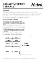
GENERAL WIRING DIAGRAM
CAUTION: Turn off electrical power at fuse or circuit breaker box before wiring xture to the power supply.
© 2019 Halco Lighting Technologies, LLC. All rights reserved. Halco and ProLED are registered trademarks of Halco Lighting Technologies. All sizes and specications are subject to change. Print Edition 11-13-19.
Halco Lighting Technologies | 2940 Pacic Drive | Norcross, GA 30071 | Toll Free 800.677.3334 | Phone 770.242.3612 | Fax 800.880.0822 | halcolighting.com | Atlanta | Cleveland | Houston | Los Angeles | Phoenix
Flood Installation Instructions
®
GENERAL SAFETY INFORMATION
• To reduce the risk of death, personal injury or property damage from re, electric shock,
falling parts, cuts/abrasions, and other hazards read all warnings and instructions included
with and on the xture box and all xture labels.
• Before installing, servicing, or performing routine maintenance upon this equipment, follow
these general precautions.
• Commercial installation, service and maintenance of luminaires should be performed by a
qualied licensed electrician.
• For Residential installation: If you are unsure about the installation or maintenance of the
luminaires, consult a qualied licensed electrician and check your local electrical code.
• DO NOT INSTALL DAMAGED PRODUCT!
• This xture is intended to be connected to a properly installed and grounded UL listed
junction box.
• Voltage input: 120-277V 50/60 Hz only
(+)LINE
(-)COMMON
GROUND
BLACK
Light
Fixture
WHITE
GROUND

Flood Installation Instructions
®
MOUNTING INSTRUCTIONS
SWIVEL ARM MOUNTING
1. Inspect components to ensure that male and female port threads and sealing
surfaces are free of burs, nicks and scratches or any foreign material.
2. Thread xture into G½ cover plate (not included) / junction box (not included)
or Landscape post (not included) as shown.
3. Seal all unused holes and threads with waterproof silicone.
4. The swivel arm on the LED Flood allows 150º of vertical aiming adjustment
depending on mounting location.
5. Connect power to xture, referencing wiring diagram on page 1.
TRUNNION MOUNTING
1. Use screw to install the xture where lighting is needed.
2. Adjust xture to desired angle.
3. Make sure the xture is rmly installed and connect with
power supply referencing wiring diagram on page 1.
POLE ARM MOUNTING(only for 70-150W model)
1. Make sure the power supply must be turn off.
2. Referencing wiring diagram on page 1, connect with power supply.
3. Attach the xture on the pole.
A
A(mm) B(mm) C(mm) D(mm)
D
C
B
FL12/FLFS12
FL30/FLFS30
FL50/FLFS50
FL70-150/
FLFS70-150
6
6
8
8
50
50
90
90
16
16
18
18
WALL MOUNTING
1. Remove the mounting plate from the back of the xture by loosening the mounting plate tightening bolt using the
screwdriver.
2. Route the junction box wires through the large center hole in the mounting plate. Align the holes on the mounting
bracket with the holes on your junction box. depending on the size of the holes in your junction box, attach the
mounting bracket to your junction box. According to the corresponding hole position, paste waterproof gasket.
3. Connect xture black wire to house black wire, the (+) line, and xture white wire to house white wire, the (-) common
by twisting the exposed wires together and using the wire nuts. Ensure no loose wires. Connect house ground wire to
the green xture ground wire, by twisting the exposed wires together and using the wire nuts.
4. Once the xture is wired, place the light xture onto the mounting plate so the top sloped grove on the plate rests on the
top sloped grove on the back of the xture. Tighten the mounting plate by tighten-ing bolt back through the hole on the
bottom of the xture until the bolt rmly pushes against the mounting plate.
5. Complete the installation.
© 2019 Halco Lighting Technologies, LLC. All rights reserved. Halco and ProLED are registered trademarks of Halco Lighting Technologies. All sizes and specications are subject to change. Print Edition 11-13-19.
Halco Lighting Technologies | 2940 Pacic Drive | Norcross, GA 30071 | Toll Free 800.677.3334 | Phone 770.242.3612 | Fax 800.880.0822 | halcolighting.com | Atlanta | Cleveland | Houston | Los Angeles | Phoenix
1
2345
/