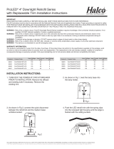
IMPORTANT
READ INSTRUCTIONS CAREFULLY BEFORE INSTALLING.KEEP THESE INSTRUCTIONS FOR FUTURE REFERENCE.
ProLED
®
xtures must be wired in accordance with the National Electrical Code and all applicable local codes. Proper grounding is required for safety.
THIS PRODUCT MUST BE INSTALLED IN ACCORDANCE WITH THE APPLICABLE INSTALLATION CODE BY A QUALIFIED ELECTRICIAN WHO IS
FAMILIAR WITH THE CONSTRUCTION AND OPERATION OF THE PRODUCT AND THE HAZARDS INVOLVED.
Halco Lighting Technologies | 2940 Pacic Drive | Norcross, GA 30071 | Toll Free 800.677.3334 | Phone 770.242.3612 | Fax 800.880.0822 | halcolighting.com | Atlanta | Chicago | Cleveland | Houston | Los Angeles | Phoenix
ProLED
®
Linear LED High Bay Gen II
Installation Instructions
®
© 2017 Halco Lighting Technologies, LLC. All rights reserved. Halco is a registered trademark of Halco Lighting Technologies. All sizes and specications are subject to change.
IMPORTANT SAFETY INFORMATION:
CAUTION: This luminaire must be wired in accordance with the National Electric Code and applicable local codes and ordinances. Proper grounding
is required for safety.
CAUTION: Installation and servicing of this luminaire should be performed by qualied personnel only.
CAUTION: Do not use this product for other than intended use. To prevent early product failure, luminaire should only be used in operating
environments ranging from -40°C (-40°F) to 50°C (122°F).
Cleaning and Maintenance:
Caution: Do not clean or maintain while the luminaire is energized. Check that the luminaire temperature is cool enough to touch. Periodically check
and remove any accumulated dirt or debris from the lens and around luminaire.
1) Clean lens with non-abrasive glass cleaning solution.
2) Do not open the luminaire to clean the LEDs. Do not touch the LEDs.
Replacement Parts:
Contact your sales representative for replacement part availability or contact Halco Customer Care at 800.677.3334.
WARNING - Risk of re or electric shock.
• Turn off electrical power at fuse or circuit breaker box before
wiring xture to the power supply.
• Turn off the power when you perform any maintenance.
• Verify that supply voltage is correct by comparing it with the
luminaire label information.
• Make all electrical and grounded connections in accordance
with the National Electrical Code and any applicable local
code requirements.
• All wiring connections should be capped with UL approved
wire connectors.
CAUTION:
RISK OF INJURY
• Wear gloves and safety glasses at all times when removing luminaire from carton,
installing, servicing or performing maintenance .
• Avoid direct eye exposure to the light source while it is on.
• Account for small parts and destroy packing material, as these may be hazardous
to children.
RISK OF FIRE
• Keep combustible and other materials that can burn away fromluminaire and
lamp/lens.
• MIN 90°C SUPPLY CONDUCTORS .
Part No. Input voltage (V) Watt (W) Input Current (A)
Luminous Flux
(LM)
Efciency
(LM/W)
Power factor CRI
Dimension
(mm)
Expected
service life
99649
120-277V
ac 50/60Hz
111 0.93-0.40 14,478 > 130 >0.9 >80 625x330x92 > 5 years
99650
120-277V
ac 50/60Hz
161 1.34-0.58 22,025 > 130 >0.9 >80 625x440x92 > 5 years
99651
120-277V
ac 50/60Hz
221 1.84-0.79 29,467 >130 >0.9 >80 1200x330x92 > 5 years
General Wiring Diagram
WARNING:
All units must be individually connected to the
AC Supply:
WARNING - All units must be connected to ac power supply:
Select appropriate access point for your installation,remove
knockout, and feed power leads through hole.
Connect the supply wire from the source to the driver.
Black = Line White = Neutral Green = Ground
**Consult with dimmer control manufacturer’s wiring instructions.
Operating Characteristic
Voltage input: 120-277V 50/60 Hz
Operating temp: -40°F (-40°C) to 122°F (50°C)
**Consult with dimmer control manufacturer’s wiring instructions