Page is loading ...

© 2017 Halco Lighting Technologies, LLC. All rights reserved. Halco and ProLED are registered trademarks of Halco Lighting Technologies. All sizes and specications are subject to change. 12-14-17.
Halco Lighting Technologies | 2940 Pacic Drive | Norcross, GA 30071 | Toll Free 800.677.3334 | Phone 770.242.3612 | Fax 800.880.0822 | halcolighting.com | Atlanta | Chicago | Cleveland | Houston | Los Angeles | Phoenix
ProLED
®
ECO 4" Downlight Installation Instructions Gen11
IMPORTANT
READ INSTRUCTIONS CAREFULLY BEFORE INSTALLING. KEEP THESE INSTRUCTIONS FOR FUTURE REFERENCE.
ProLED luminaires must be wired in accordance with the National Electrical Code and all applicable local codes. Proper grounding is required for safety.
THIS PRODUCT MUST BE INSTALLED IN ACCORDANCE WITH THE APPLICABLE INSTALLATION CODE BY A QUALIFIED ELECTRICIAN WHO IS
FAMILIAR WITH THE CONSTRUCTION AND OPERATION OF THE PRODUCT AND THE HAZARDS INVOLVED.
WARNING - Risk of re or electric shock. ProLED Downlight Series installation requires knowledge of the luminaires’ electrical systems. If not qualied,
DO NOT attempt installation. Contact a qualied electrician.
WARNING - Risk of re or electric shock. Install this kit only in the luminaires that have the construction features and dimensions shown in the
photographs and/or drawings. DO NOT make or alter any open holes in an enclosure of wiring or electrical components during
kit installation.
WARNING - To prevent wiring damage or abrasion, DO NOT expose wiring to edges of sheet metal or other sharp objects.
WARNING - Risk of re or electric shock. DO NOT alter, relocate, or remove wiring, lampholders, power supply, or any other electrical component.
WARNING - This device is not intended for use with emergency exits.
DANGER - RISK OF SHOCK-DISCONNECT POWER BEFORE INSTALLATION
CAUTION: To avoid possible electrical shock, be sure that power supply is turned off at fuse box or circuit breaker before installing or servicing
luminaire. For your safety, read and understand instructions completely before beginning installation.
WARRANTY INFORMATION:
This product is warranted for 5 years from the date of purchase. If this product does not perform to the specications supplied on this package, send
an email or write to the address below for product return and replacement. This replacement is the sole remedy available. Liability for incidental or
consequential damage is expressly excluded. Visit www.halcolighting.com for full warranty details and dimmer compatibility information.
®
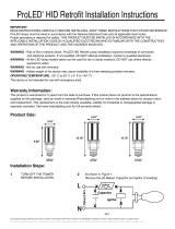
INSTALLATION INSTRUCTIONS:
1. Turn OFF power at switch and fuse box or
circuit breaker.
2. Remove existing trim installed in recessed housing
(if necessary).
3. If applicable, slide lamp holder bracket to its upward
maximum position. If the lamp holder bracket is less than
4.5 inches from the bottom edge of the xture enclosure,
the lamp holder bracket must be removed.
4. If necessary, remove the lamp holder mounting bracket
(see FIG.2) and the lamp holder from the bracket
(see FIG.2), then attach the provided label to the
existing luminaire.
5. Install adapter into socket (see FIG. 3).
Components Included
A. Medium Base Adapter
B. Retrot Assembly
Remove lamp
holder
bracket
(if Necessary)
FIG. 3
FIG. 1A
FIG. 2
Install the
Adapter
FIG. 1B Diagram of recessed luminaire
Packaging Contents
Before beginning installation on this product, make sure all parts are present. Compare parts with package contents list and diagram as below. If any
part is missing or damaged, do not attempt to assemble, install or operate this product.

Halco Lighting Technologies | 2940 Pacic Drive | Norcross, GA 30071 | Toll Free 800.677.3334 | Phone 770.242.3612 | Fax 800.880.0822 | halcolighting.com | Atlanta | Chicago | Cleveland | Houston | Los Angeles | Phoenix
© 2017 Halco Lighting Technologies, LLC. All rights reserved. Halco is a registered trademark of Halco Lighting Technologies. All sizes and specications are subject to change. 12-14-17.
INSTALLATION INSTRUCTIONS Continued:
6. Connect the Orange connectors together (see FIG. 4B).
7. Insert torsion springs into luminaire housing brackets (see FIG 5).
8. Gently push up trim and torsion springs so they begin to expand and lift trim in place (see FIG. 6).
INSTALLATION into Existing Recessed LED Luminaire with Compatible orange connectors:
1. Turn OFF Power at switch and fuse box or circuit breaker
2. Remove existing trim installed in recessed housing (if necessary).
3. Discard medium base adapter.
4. Connect the orange connectors together (see FIG. 2A).
5. Insert torsion springs into xture brackets (see FIG. 2B).
6. Gently push up trim and torsion springs so they begin to expand and lift trim in place (see FIG. 3).
Min. Lamp Compartment Dimensions
135mm (53/8 in) DIA X 190mm (71/2 in) HEIGHT When
used in 5 inch recessed Luminaire
Min. Lamp Compartment Dimensions
154mm (6 in) DIA X 188mm (71/2 in) HEIGHT When used
in 6 inch recessed Luminaire
FIG. 4B Connect the orange
connectors
FIG. 1B Diagram of
recessed luminaire
FIG. 6
FIG. 6
FIG. 4A
FIG. 1A
FIG. 5
FIG. 2B
FIG. 2A Connect the orange
connectors
THE RETROFIT KIT IS ACCEPTED AS A COMPONENT
OF LUMINAIRE WHERE THE SUITABILITY OF THE
COMBINATION SHALL BE DETERMINED BY UL OR
AUTHORITIES HAVING JURISDICTION.
Orange
Terminals
/