© 2016 Halco Lighting Technologies, LLC. All rights reserved. Halco and ProLED are registered trademarks of Halco Lighting Technologies. All sizes and specications are subject to change. 12-16-16.
Halco Lighting Technologies | 2940 Pacic Drive | Norcross, GA 30071 | Toll Free 800.677.3334 | Phone 770.242.3612 | Fax 800.880.0822 | halcolighting.com | Atlanta | Carlstadt | Cleveland | Houston | Los Angeles | Phoenix
ProLED
®
4", 6" and 8" LED Commercial Downlight Retrot
Installation Instructions
IMPORTANT
READ INSTRUCTIONS CAREFULLY BEFORE INSTALLING. KEEP THESE INSTRUCTIONS FOR FUTURE REFERENCE.
PROLED LUMINAIRES MUST BE WIRED IN ACCORDANCE WITH THE NATIONAL ELECTRICAL CODE AND ALL APPLICABLE LOCAL CODES.
PROPER GROUNDING IS REQUIRED FOR SAFETY. THIS PRODUCT MUST BE INSTALLED IN ACCORDANCE WITH THE APPLICABLE
INSTALLATION CODE BY A QUALIFIED ELECTRICIAN WHO IS FAMILIAR WITH THE CONSTRUCTION AND OPERATION OF THE PRODUCT AND
THE HAZARDS INVOLVED.
WARNING - Risk of re or electric shock. ProLED Downlight Series installation requires knowledge of the luminaires’ electrical systems. If not qualied,
DO NOT attempt installation. Contact a qualied electrician.
WARNING - Risk of re or electric shock. Install this kit only in luminaires that have the construction features and dimensions shown in the photographs
and/or drawings. Luminaires wiring, power supply, or other electrical parts may be damaged when drilling for installation of retrot assembly
hardware. Inspect wiring and components for damage. DO NOT make or alter any open holes in an enclosure of wiring or electrical
components during kit installation.
WARNING - To prevent wiring damage or abrasion, DO NOT expose wiring to edges of sheet metal or other sharp objects.
WARNING - Risk of re or electric shock. DO NOT alter, relocate, or remove wiring, lamp holders, power supply, or any other electrical component.
WARNING - Install this kit only in the luminaires that has the construction features and dimensions shown in the photographs and/or drawings and
where the input rating of the retrot kit does not exceed the input rating of the luminaire.
WARNING - This device is not intended for use with emergency exits.
DANGER - RISK OF SHOCK-DISCONNECT POWER BEFORE INSTALLATION
CAUTION: To avoid possible electrical shock, be sure that power supply is turned off at fuse box or circuit breaker before installing or servicing
luminaire. For your safety, read and understand instructions completely before beginning installation.
WARRANTY INFORMATION:
This product is warranted for 5 years from the date of purchase. If this product does not perform to the specications supplied on this package, send
an email or write to the address below for product return and replacement. This replacement is the sole remedy available. Liability for incidental or
consequential damage is expressly excluded. Visit www.halcolighting.com for full warranty details and dimmer compatibility information.
®
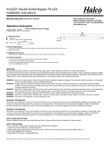
Product Code
Input Voltage
(V)
Input Current
(mA)
Input
Wattage (W)
Color Accuracy
(CRI)
Lumens
(lm)
Ceiling Hole
inches (mm)
CDL4FR10/9XX/RTJB/LED 110-277 0.089 10 90 700 4" (101.6mm) - 4.30" (109.2mm)
CDL6FR15/9XX/RTJB/LED 110-277 0.127 15 90 1000 4.80" (121.9mm)- 6.20" (157.4mm)
CDL8FR30/9XX/RTJB/LED 110-277 0.255 30 90 2000 7.50" (190.5mm) - 8.20" (208.2mm)
Please read carefully and save these instructions, as you may need them at a later date.
1. Suitable for use in type ic or non-ic recessed luminaires - min lamp compartment min 4 inch diameter.
2. Suitable for dry, damp locations.
3. Only those open holes indicated in the photographs and/or drawings may be made or altered as a result of kit installation. Do not leave any other
open holes in an enclosure of wiring or electrical components.
4. Do not make or alter any open holes in an enclosure of wiring or electrical components during kit installation.
5. Warning – to prevent wiring damage or abrasion, do not expose wiring to edges of sheet metal or other sharp objects.
6. This retrot kit is accepted as a component of a luminaire where the suitability of the combination shall be determined by authorities having jurisdiction.
7. Installers should not disconnect existing wires from lampholder terminals to make new connections at lampholder terminals. Instead installers
should cut existing lampholder leads away from the lampholder and make new electrical connections to lampholder.