
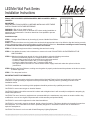
LED
Mini Wall Pack Series
Installation Instructions
Models: MWP12/U50BZ/PC,MWP24/U50BZ/PC, MWP12/U40BZ/PC,MWP24/
U40BZ/PC
IMPORTANT
READ INSTRUCTIONS CAREFULLY BEFORE INSTALLING. KEEP THESE
INSTRUCTIONS FOR FUTURE REFERENCE.
WARNING
- Risk of fire or electric shock.
WARNING - Make certain power is switched OFF before starting installation or
attempting any maintenance. Consult an electrician if not qualified to prevent
electrical shock.
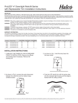
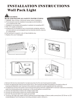
Installation steps:
STEP 1: Unhinge Glass Refractor by loosening (2) screws. Handle Glass Refrac-
tor with care.
STEP 2: Position the xture over the junction box and mark the appropriate holes to be drilled to align the housing correctly
over the junction box then secure with hardware provided with the junction box. Use silicone caulking on back of housing
in contact with wall surface to seal against moisture and insects.
STEP 3: Pull wires through center hole of mounting plate and rear housing.
STEP 4: Use additional screws, bolts or fasteners to secure to the wall. DO NOT RELY ON FASTENERS AT THE
JUNCTION BOX.
STEP 5: With the electrical power turned off at the circuit breaker, make the following connections.
This xture automatically adjusts for voltages between 120VAC-277VAC.
- Connect xture ground wire to the junction box ground screw terminal.
- Connect the black xture lead to the (+) hot line supply lead.
- Connect the white xture lead to the (-) common supply lead.
- Use approved wire connectors to connect xture leads to supply leads and make wire splices inside the
junction box.
STEP 6: Replace the Glass Refractor, making sure the gasket is properly sealed around the perimeter of the lens to ensure
a weather tight seal.
STEP 7: Turn the power back on.
IMPORTANT SAFETY INFORMATION:
CAUTION: This xture must be wired in accordance with the National Electrical Code and applicable local codes and
ordinances. Proper grounding is required to insure personal safety. Carefully observe grounding procedure under
installation section.
CAUTION: Installation and servicing of this equipment should be performed by qualied personnel only.
CAUTION: Do not mount near gas or electrical heaters.
CAUTION: Equipment should be mounted in locations and at heights where it will not readily be subjected to tampering by
unauthorized personnel.
CAUTION: The use of accessory equipment not recommended by the manufacturer may cause an unsafe condition. Any
modication or use of non-original components will void the warranty and product liability.
CAUTION: Do not use this equipment for other than intended use.
CAUTION: Do not install in dead air, sheltered, buried or boxed in location. This xture should not be installed in areas that
will entrap heat. It is not intended to be used in potentially dangerous or hazardous locations such as ammable or
explosive atmospheres.
CAUTION: This xture is not for use with UL924 Emergency Lighting Equipment.
®
© 2018 Halco Lighting Technologies, LLC. All rights reserved. Halco and ProLED are registered trademarks of Halco Lighting Technologies. All sizes and specications are subject to change. Print Edition 06-13-18
Halco Lighting Technologies | 2940 Pacic Drive | Norcross, GA 30071 | Toll Free 800.677.3334 | Phone 770.242.3612 | Fax 800.880.0822 | halcolighting.com | Atlanta | Cleveland | Houston | Los Angeles | Phoenix

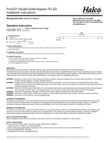
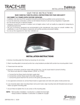
Mounting
1. Remove the lens by removing the screw securing it to the rear housing and set aside.
2. Remove screws and remove reector from rear housing.
Power From Conduit
1. Knock out two plugs in rear housing and apply the gasket to the back surface of housing. Attach xture to mounting
surface with two screws.
a. For surface conduit: Remove the threaded plug from the bottom of the rear housing.
b. For conduit entry from back: Knock out the conduit entrance on back of xture.
2. Complete the wiring to the power source and ground (refer to wiring instructions).
3. To ensure rain tight seal, apply silicone caulking around back edges of xture.
4. Replace reector.
5. Replace front lens by reversing procedure used to remove it.
Mounting Over Outlet Box
1. Knock out appropriate holes around outlet hole in rear housing and apply the gasket to the back surface of housing.
Fasten the rear housing to the outlet box using the screws supplied with the outlet box.
2. Complete the wiring to the power source and ground (refer to wiring instructions).
3. To ensure rain tight seal, apply silicone caulking around back edges of xture.
4. Replace reector.
5. Replace front lens by reversing procedure used to remove it.
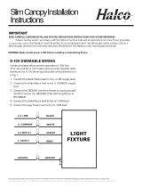
Fixture Wiring
NOTE: This luminaire is rated for 120-277V 50/60Hz only.
1. Make the following electrical connections in the mounting box or junction box:
a. Connect the black xture lead to the voltage supply lead
b. Connect the white xture lead to the neutral supply lead
c. Connect the ground lead to the supply ground lead.
LED
Mini Wall Pack Series
Installation Instructions
®
© 2018 Halco Lighting Technologies, LLC. All rights reserved. Halco and ProLED are registered trademarks of Halco Lighting Technologies. All sizes and specications are subject to change. Print Edition 06-13-18
Halco Lighting Technologies | 2940 Pacic Drive | Norcross, GA 30071 | Toll Free 800.677.3334 | Phone 770.242.3612 | Fax 800.880.0822 | halcolighting.com | Atlanta | Cleveland | Houston | Los Angeles | Phoenix
Important:
This product is warranted for 5 years from the date of purchase, based on 10 hours of use per day. If this product does not
perform to the specications supplied on this package, send an email or write to the address below for product return and
replacement. This replacement is the sole remedy available. Liability for incidental or consequential damage is expressly
excluded. Visit www.halcolighting.com for full warranty details and compatibility information.
Warranty Information:
This product is warranted for 5 years from the date of purchase, based on 10 hours of use per day. If this product does not perform to the specications
supplied on this package, send an email or write to the address below for product return and replacement. This replacement is the sole remedy available.
Liability for incidental or consequential damage is expressly excluded. Visit www.halcolighting.com for full warranty details and compatibility information.
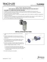
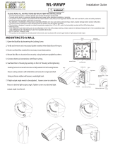
External cable
GND L N
Fixture Housing GRD
LED
WHITE(N) RED(LED+)V+
BLACK(DL)RIVER
GND BLACK(LED
V
-)
-
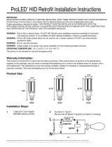
Driver Wiring Diagram:
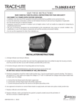
RED(LOAD)
WHITE(N)
BLACK(L)
DRIVER
GND
N
L
L
Photocell Wiring Diagram:
External cable
N GND
Photocell
-
 1
1
-
 2
2


Halco Lighting Technologies MWP24/U50BZ/PC 10147 Installation guide
- Type
- Installation guide
- This manual is also suitable for
Ask a question and I''ll find the answer in the document
Finding information in a document is now easier with AI
Related papers
-
Halco Lighting Technologies LBH3/221/850/UNV/LED2 99651 Installation guide
-
Halco Lighting Technologies CDL6FR15/950/RTJB/LED 99617 Installation guide
-
Halco Lighting Technologies 24VPL49/835/LED3 81978 Installation guide
-
Halco 22FSEPL/8DU 10331 Installation guide
-
 Halco Lighting Technologies CSP/40U50/MS 10294 Operating instructions
-
Halco Lighting Technologies 82119 Specification
-
 Halco Lighting Technologies HID54/850/MV2/LED 84013 Operating instructions
-
 Halco Lighting Technologies DL4FR9/950/RT2/LED 99826 Installation guide
-
 Halco Lighting Technologies PAR38NFL17/927/WH/LED 83030 Specification
-
 Halco Lighting Technologies T8FR14/850/BYP3/DE/LED10PK 89003 Installation guide


Other documents
-
 BARRON TLED804 Series Die-cast Globe Vaportight Installation guide
-
 BARRON TL106EX Series Large Die-cast Installation guide
-
Halco T5FR25/850/BYP/HO/LED Installation guide
-
-
 kadision LED Wall Pack Installation guide
-
 BARRON TLED111P Series Half Round Wall Sconce Installation guide
-
-
 WAREHOUSE-LIGHTING COM WL-MAWP WareLight Mini Adjustable Wall Pack Installation guide
-
-


