Midmark Procenter Systems Installation guide

Category
Sanitary ware
Type
Installation guide

Midmark Procenter Systems, the ultimate dental delivery solution, offer a range of features to enhance your practice's efficiency and patient care. With its versatile design, Procenter can be customized to fit your specific needs, whether you're performing routine checkups, complex procedures, or anything in between. The system's intuitive controls and seamless integration with dental chairs ensure smooth operation and optimal comfort for both you and your patients.

Midmark Procenter Systems, the ultimate dental delivery solution, offer a range of features to enhance your practice's efficiency and patient care. With its versatile design, Procenter can be customized to fit your specific needs, whether you're performing routine checkups, complex procedures, or anything in between. The system's intuitive controls and seamless integration with dental chairs ensure smooth operation and optimal comfort for both you and your patients.

1
© 2011 Midmark Corp. | 60 Vista Drive Versailles, OH 45380 USA | 1-800-643-6275 | 1-937-526-3662 |
003-1256-00 Rev. S (11/3/16)
Procenter Delivery Mounted on a Free Standing
Treatment Console (FTC) Installation
Components:
none
Special Tools:
none
Electrical Requirements:
24 VAC, 3.2 Amp
13VAC, 2 Amp
DA2230i
Note
Locate three holes toward
front of cabinet for proper
rotation when installing.
Note
Leave push retainers
on screws for install.
Cabinet Mount Arm
(Pivoting)
Step 1: Align mounting holes in leveling plate
and cabinet mount arm plate with
mounting holes in cabinet.
Secure with screws but do not tighten.
Cabinet Mount Arm
(Pull Out)
Attention
These instructions apply to Midmark cabinetry. For other
cabinetry, additional steps may be required. Refer to 12:00
Procenter Delivery Mounting Kit Installation Instructions
[002-10005-00] to confirm necessary steps have been com-
pleted before proceeding with this installation.
NextNext
BackBack
midmark.com
Style G
2
© 2011 Midmark Corp. | 60 Vista Drive Versailles, OH 45380 USA | 1-800-643-6275 | 1-937-526-3662 |
DA2372i
Mounting Control Panel
Step 2: Align top and bottom
slides on delivery panel
with slides on cabinet and
carefully move into position.
Step 3: Route foot control
tubing through hole
in cabinet base.
Secure with screws.
Step 1: Position bearing race at end of each slide
that is attached to cabinet.
Note: Slides maybe mounted on RH side of cabinet.
NextNext
BackBack
midmark.com
Style G
3
© 2011 Midmark Corp. | 60 Vista Drive Versailles, OH 45380 USA | 1-800-643-6275 | 1-937-526-3662 |
80 PSI
30 PSI
Regulator Installation
Step 1: Insert regulator into compression
fitting of shut-off valve and
tighten compression fitting.
Note: Delivery and Assistant’s Unit Tubing Connections are
located in cabinet base.
Note
The diagram shows all possible connections for the delivery system.
Foot Control used for Delivery Unit (Only)
Vacuum Connections used for Assistant’s Unit (Only).
Transformer
Air Pressure
(Optional)
1/8
Red
1/8
Red
1/8
Red
Air Supply
(80 - 100 PSI)
Master
Pilot
Shut-Off
Master
Pilot
Shut-Off
Water Supply
(30 - 50 PSI)
Foot Control
(Procenter Delivery Unit Only)
Rib
1/4 Grey (Ribbed)
1/4 Grey (Plain)
1/8 Grey (Above 1/4 Ribbed)
1/8 Grey
1/8
Green
1/8
Orange
1/4
Clear
To Handpiece Coolant Air
To Pilot Air for Coolant Water
To Handpiece Drive Air
1/8 or 1/4 Yellow (Filtered / Regulated Air - [80 PSI])
Air To Syringe
1/8 Brown (Filtered / Regulated Air - [80 PSI])
1/8 Purple (Unltered / Unregulated Air - [80 - 100 PSI])
1/8 Red (80 - 100 PSI])
Air To Water Bottle
Air To Master
ON/OFF Switch
Air From Master
ON/OFF Switch
Syringe Tubing
5/8 Vacuum
Ribbed
Side
Instrument Water
from Control
Panel / Water
Bottle Assembly
City Water to/ Water
Selector Valve
Vacuum Supply Tube
(Assistant’s Unit Only)
Regulator
Compression
Fitting
Shutoff
Valve
Shutoff
Valve
Compression
Fitting
Regulator
AIR REGULATOR WATER REGULATOR
Tubing Connections (J-Box)
1/8
Blue
Master Pilot Shut-Off
Input
Unltered
Output
Filtered
Output
INACTIVE - no
air from master
switch
ACTIVE - air coming
from master switch
NextNext
BackBack
midmark.com
Style G
Color Page
4
© 2011 Midmark Corp. | 60 Vista Drive Versailles, OH 45380 USA | 1-800-643-6275 | 1-937-526-3662 |
DA2233-1i
Step 2: On the Pivoting Unit,
Insert Unit Mount Arm
into Cabinet Mount Arm.
Mounting
Screws
Leveling
Screws
Work
Surface
Leveling
Plate
Mount
Arm
Cabinet
Mount Arm
Leveling
Screws
Work Surface / Unit Mount Arm
Installation & Adjustment
Cabinet Mount
(Pull Out)
Cabinet Mount
(Pivoting)
Step 1: Align desired mounting holes in work
surface, leveling plate, and mount arm.
Secure with screws.
Work
Surface
Step 3: Leveling Work Surface:
Loosen mounting screws.
Adjust leveling screws.
Retighten mounting screws.
Step 4: On the Pivoting Unit,
Adjust drag by loosening
or tightening set screws
at pivot points.
Pivot Points
& Set Screws
Mounting
Screws
Leveling
Screws
Leveling
Plate
Maximum Weight Limitation
40 lbs. (18 kg)
NextNext
BackBack
midmark.com
Style G
5
© 2011 Midmark Corp. | 60 Vista Drive Versailles, OH 45380 USA | 1-800-643-6275 | 1-937-526-3662 |
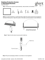
Routing / Securing Tubing
DA2394i
Equipment Alert
When securing tubing, allow
sufficient slack in tubing for
movement of control panel / mounting
arm. Failure to do so could result in tub-
ing becoming disconnected or damage.
Step 2: Bundle tubing from control
panel and install bracket; then
secure bracket with screws.
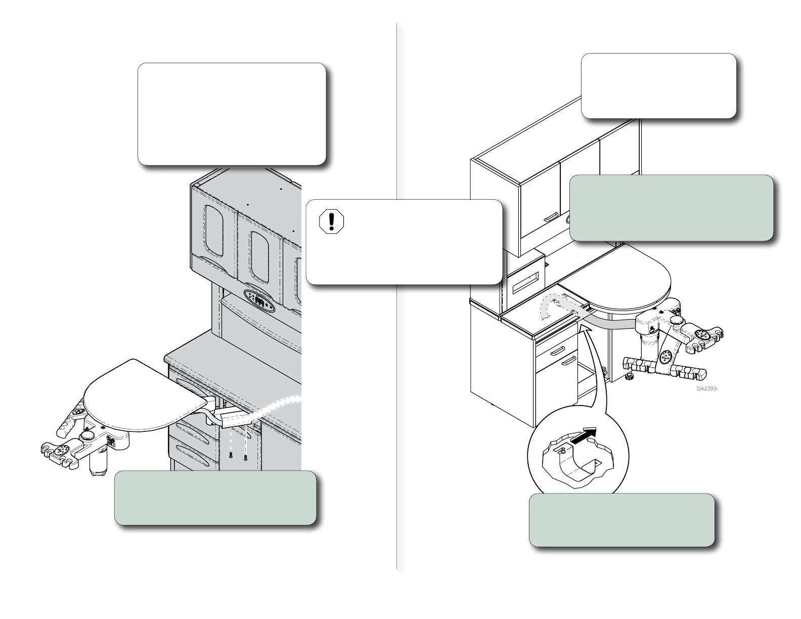
Cabinet Mount
(Pivoting)
Note
Adhesive backed mounting platforms
are provided for units without control
panel.
Apply mounting platform to inside of
cabinet and secure vacuum with wire
tie: then go to step 2.
Cabinet Mount
(Pull Out)
Step 1: Loosen screws on both
side of mounting brackets
and remove bracket..
Step 2: Bundle tubing from Doctor’s /
Assistant’s Delivery Units and
install in brackets then secure
with screws.
Note
For ease of installation it may
be helpful to extend the work
surface by pulling it outward.
NextNext
BackBack
midmark.com
Style G
6
© 2011 Midmark Corp. | 60 Vista Drive Versailles, OH 45380 USA | 1-800-643-6275 | 1-937-526-3662 |
DA2395i
Note
The Work Surface assembly can accommodate accessories
(9” x 13” Tray Assembly or a Tub Support). The assembly can
be installed for either right or left hand operation.
Step 4: Install the Tray Assembly or
Tub Support.
Step 1: If necessary, replace base of tray clamp
assembly by removing screws, thumb
screw, and clamp plate, place new base
in place and re-assemble.
Note: Used on Laminate and Quartz work surfaces.
Step 3: Insert the flange bearing
into tray clamp assembly.
Step 2: Position tray clamp assembly onto
work surface and tighten thumb screw.
Tray / Tub Assembly Installation
for Pull Out Unit
Base used with
Corian® tops
Base used with
Laminate and
Quartz tops.
NextNext
BackBack
midmark.com
Style G
7
© 2011 Midmark Corp. | 60 Vista Drive Versailles, OH 45380 USA | 1-800-643-6275 | 1-937-526-3662 |
DA2371i
J13
J11
J10
Note
The following procedure applies only
when using this delivery system with a
Midmark Dental Chair.
If not using a Midmark Dental Chair, or if
the delivery system does not include the
optional Chair Position Touch Pad, this
procedure is not necessary.
Step 1: Connect 15 ft. wire harness
to touch pad wire harness.
15 ft.
Extension
Note
Open Equipment Base mounts to
Center Console with 3 screws.
On Side Delivery Units, the shipping
leg must be removed first.
Hydraulic
Cover
Step 2: Route wire harness out
through hole in front of
base and install bushing.
12 in.
Extension
Chair PC
Board
J2
Step 3: Remove Hydraulic
Cover and route wire
harness behind base
cover of chair.
Step 4: Connect 12 in. wire harness
extension to J2 position on
Chair PC Board.
Step 5: Connect 12 in. wire
extension to wiring
harness.
Step 6: Install Hydraulic Cover.
Chair Control Touch Pad
Connections (Optional)
LH Mount (Shown)
NextNext
BackBack
midmark.com
Style G
8
© 2011 Midmark Corp. | 60 Vista Drive Versailles, OH 45380 USA | 1-800-643-6275 | 1-937-526-3662 |
Tubing Connections
(Vacuum Instrument Arm Assembly)
Water
Selector
Valve
(Optional)
FlushValve (N.C.)
2-Way Manual
Momentary
Double Pinch
Valve 1/8"
Push
30 PSI
Water Quick
Disconnect
Master
On/Off
Valve
80 PSI
Air Quick
Disconnect
N.C. Limit
Switch
N.C. Limit
Switch
N.C. Limit
Switch
City
Water
Syringe Tubing
Water
Air
Capped
To Umbilical
Vacuum Supply
City
Water
Bottle
Water
Water
Air
Solids
Collector
Vacuum
Open
Closed
High
Volume
Evacuator
(HVE)
Saliva
Ejector
Open
Closed
Violet
Brown
Yellow
Blue
Blue
Blue
Blue
Blue
Violet
Black
Red
White
Blue
Brown
Yellow
Violet
Orange
Green
Blue
Blue
24 V
24 V
C
D
F
0 V
E
B
A
Brown
0 V
COM
NC
COM
NC
COM
NC
Yellow
To
Junction
Box
Assistant's
Unit
w/ Optional
Switches
Brown
Orange
Yellow
Violet
Red
Red
Violet
Blue
1/4"
Blue
1/8"
Blue
Yellow
Yellow
Yellow
Red
Blue
Blue
Yellow
Blue
Blue
Blue
Brown
Yellow
Orange
Brown
Water
Bottle
Cap
In line Regulator
Umbilical
NextNext
BackBack
midmark.com
Style G
Color Page
  • Page 1 1
  • Page 2 2
  • Page 3 3
  • Page 4 4
  • Page 5 5
  • Page 6 6
  • Page 7 7
  • Page 8 8

Midmark Procenter Systems Installation guide

Category
Sanitary ware
Type
Installation guide

Midmark Procenter Systems, the ultimate dental delivery solution, offer a range of features to enhance your practice's efficiency and patient care. With its versatile design, Procenter can be customized to fit your specific needs, whether you're performing routine checkups, complex procedures, or anything in between. The system's intuitive controls and seamless integration with dental chairs ensure smooth operation and optimal comfort for both you and your patients.

Ask a question and I''ll find the answer in the document

Finding information in a document is now easier with AI