Page is loading ...

USER MANUAL
LED FLUSH MOUNT KIT
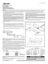
LED CONTROLLER
EXTENSION CABLE
MOUNTING
GROMMET x 2pcs
LIGHTHEAD x 2pcs
CONTENTS
WIRING & FUNCTIONS
INSTALLATION - FLUSH MOUNT
Select a mounting location and drill one 1″ (25.4mm) cut-out.
1
Front side of the
mounting surface
Lighthead
Mounting
grommet
NOTE: Mounting surface thickness @ 0.8~2.0mm
Ø1″ (25.4mm)
Ensure that triangle mark on the lens is aligned vertically.
3
From the front, install MOUNTING GROMMET
onto the cut-out, and then insert the LIGHTHEAD.
2
Where necessary, apply silicone around the reverse
side to prevent from rotating.
4
1Double [2Hz]
Flash Pattern
2 Single [2Hz]
3 Triple [2Hz]
4Quad [2Hz]
5Single
6 Double
7 Quad
8Quint
9 Mega
10 Ultra
11 Single-Quad
12 Single H/L
13 Steady EF *
14 Steady Scene
15 Random
16 Double [2Hz] (SPLIT)
17 Single [2Hz] (SPLIT)
18 Triple [2Hz] (SPLIT)
19 Quad [2Hz] (SPLIT)
20 Single (SPLIT)
21 Double (SPLIT)
22 Quad (SPLIT)
23 Quint (SPLIT)
24 Mega (SPLIT)
25 Ultra (SPLIT)
26 Single-Quad (SPLIT)
27 Single H/L (SPLIT)
12-24VDC
86-F01710-0021.0
Front side of the
mounting surface
NOTE: Make sure to cover
all unused bare wires.
To the 2nd Lighthead
(via the extension cable)
Reverse side of the
mounting surface
Front side of the
mounting surface
Lens
Reverse side of
the mounting
surface
SILICONE
SILICONE
For Synchronization:
Connect YELLOW wires of all lightheads together for synchronization.
(All the lightheads should be set to the same Flash Pattern)
For Warning Colour Mode:
Each Warning Mode (RED, WHITE or RED+WHITE) may be set to warning
in , or . To change Warning Colour Mode:
1. Choose the desired warning mode to change and apply +VDC to its activation wire
(RED, WHITE or RED+WHITE) with YELLOW wire simultaneously to enter Setting
Mode; lighthead will display short flashes in its current Colour Mode.
▪ Colour 1 (Warning Mode 1 Pre-set)
▪ Colour 2 (Warning Mode 2 Pre-set)
▪ Colour 1 alt. 2 (Warning Mode 3 Pre-set)
2. Remove YELLOW wire from +VDC and momentarily apply to +VDC again to change
Colour Mode.
3. Once in desired Colour Mode, save and Exit Setting Mode by powering off the lighthead.
For Flash Pattern:
While a warning mode is actiaved, momentarily apply +VDC to YELLOW wire:
▪ once for next pattern
▪ quick three times to reset to FP#1 (see flash pattern chart)
COLOUR
1 2
COLOUR
1
COLOUR
2
To Chassis Ground:...........................................BLACK
To+VDC to activate Warning Mode 1:....................RED
(Recommend Fuse Rating @ 2A)
To+VDC to activate Warning Mode 2:................WHITE
(Recommend Fuse Rating @ 2A)
To+VDC to activate Warning Mode 3:...(RED + WHITE)
For Synchronization and Flash Pattern:..........YELLOW
OPERATION
NOTE: Optical stripes must align
vertically to meet approved regulation.
Lighthead
Silicone
(user supplied)
LED Controller
NOTE: Each warning mode may be set to different Flash Pattern & Colour Mode.
* For use with external flasher controller.

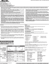
INSTALLATION - BRACKET MOUNT (sold-separately)
WIRING 2 KITS TOGETHER
Below is a schematic diagram for wiring 2 kits together.
Yellow wires from both controllers must be connected together for synchronization.
▪ When Flash Pattern 1~12 is selected: All Heads will flash simultaneously.
▪ When Flash Pattern 15~26 is selected: Head 1A&2A will flash alternatively with Head 1B&2B.
NOTE: To have Head 1A&2B alternate with 1B&2A,
simply reverse the lighthead outlets on one of the
Controllers; (both kits must be in Flash Pattern 15~26).
*refer to Flash Pattern chart on opposite page.
Ensure that triangle mark on the lens is aligned vertically.
2
Secure the LIGHTHEAD onto the BRACKET with a screw.
3
From the front, install the MOUNTING GROMMET
onto the BRACKET, and insert the LIGHTHEAD.
1
lighthead
mounting
grommet
Front side of
mounting bracket
RED
YELLOW
BLACK
ON/OFF
12V@2A / 24V@2A FUSE
(user-supplied)
CHASSIS
GROUND
EXTENSION CABLE
to GND
BLACK
EXTENSION CABLE
to GND
Unit1 Controller Unit2 Controller
NOTE: The mounting area for controllers varies from vehicle to vehicle.
HEAD 1A
HEAD 1B
HEAD 2A
HEAD 2B
Secure the BRACKET onto the desired mounting
surface with screws.
4
lens
Screw
(M3 x 8mm)
Reversed side of
the mounting bracket
Mounting
Surface
screws
(#6 x 18mm)
Mounting
Surface
NOTE: Optical stripes must align
vertically to meet approved regulation.
/