Cell2 OF01 User manual

Type
User manual

This manual is also suitable for

Cell2 OF01: Experience the future of emergency lighting with our cutting-edge warning system. This versatile device offers multiple flash patterns, synchronization, and function wire control for enhanced safety and customization. Ideal for commercial vehicles, construction sites, or emergency response teams.

Cell2 OF01: Experience the future of emergency lighting with our cutting-edge warning system. This versatile device offers multiple flash patterns, synchronization, and function wire control for enhanced safety and customization. Ideal for commercial vehicles, construction sites, or emergency response teams.

86-F01910-0101.0
12-24VDC
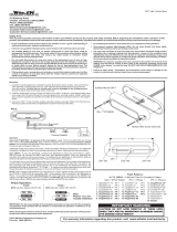
SINGLE LED LIGHTHEAD
WIRING
To +VDC for Warning Mode (fuse @ 1A)..….…..…..... RED
To -VDC or Chassis Ground……………………....... BLACK
For Synchronisation and Flash Pattern….......… YELLOW
Connect YELLOW wires of all lightheads together for synchronisation.
(All lightheads should be set to the same Flash Pattern and synchronised to comply with ECE R65)
Function Wire - OFF Override (default) or
Cruise Mode.............................................................. WHITE
Apply this wire to +VDC with RED wire for OFF Override or Cruise Mode.
OPERATION
For Flash Pattern Selection:
While activating a warning mode, momentarily apply YELLOW wire to +VDC:
• Once to the next pattern.
• Quick three times to the default flash pattern.
Function Wire Setting - OFF Override or Cruise Mode:
1. Apply +VDC to RED , WHITE and YELLOW wires simultaneously then remove just the YELLOW wire to enter FUNCTION
WIRE SETTING; the lighthead will display short flashes:
• Triple flash = OFF Override (default) • Quad flash = Cruise Mode
2. To change Function, momentarily apply YELLOW wire to +VDC.
3. Save and exit FUNCTION WIRE SETTING by disconnecting all power.
Reset to Factory Default Settings:
1. Apply +VDC to RED and YELLOW wires simultaneously then remove YELLOW wire to enter SETTING MODE.
2. Apply to +VDC for more than 5 seconds. The lighthead will display fast short flashes to signify restoring successfully.
3. Save and exit SETTING MODE by disconnecting all power.
7
9
8
1
2
3
4
5
6
FP#
Single H/L
Single-Triple-Quint
Double [R65]*
Single [2Hz]
Triple [2Hz]
Quad [2Hz]
Random
Steady EF**
Single-Quad
Flash Pattern
For Simultaneous or Alternating Synchronisation:
1. Apply +VDC to RED and YELLOW wires simultaneously then remove
YELLOW wire to enter SETTING MODE; the lighthead will display short flashes:
• Single flash = Group 1 • Double flash = Group 2
2. To change Group, momentarily apply YELLOW wire to +VDC.
• Lightheads of the same Group will flash together.
• Lightheads of the different Group will flash alternately.
Note: To comply with ECE R65, 4 units need to be synchronised and set to the same group.
3. Save and exit SETTING MODE by disconnecting all power.
* Actual approval will be based on the
model ordered.
** For use with external flash controller.
INSTALLATION (Covert Mount for Side Mirror with Turn Signal Light)
The disassembling method of the original vehicle parts will be different based on each vehicle manufacturer and model,
please refer to original vehicle manufacturer's manual before installation.
IMPORTANT:
3
Test the lighthead before reassembling the side mirror cover
and mirror back.
1. Remove the front mirror using a plastic pry tool.
2. Remove the side mirror cover by pushing the clips or
loose screws from inside to access the harness assembly.
3. Disconnect the wire harness and disassemble the turn
signal light assembly from the side mirror unit.
1
Mirror Side Mirror Cover
Turn Signal Light
1. Drill an 8.5mm hole with 4mm depth on the inner lens
or reflector of the turn signal light assembly.
2. Apply silicone and fix the lighthead into the assembly.
3. Assemble the turn signal light back into side mirror set.
4. Route lighthead's wire into vehicle chassis and
connect the wires to the switch accordingly.
Note: Ensure the mark is oriented upward for correct
optical distribution.
2
Ensure the dented mark is oriented
upward for best viewing angle.
Silicone
SILICONE
SILICONE
The lightheads must be set up in a set of four units to meet ECE R65 Cat. X. (Amber, Blue, Red)
Follow the diagram and position the lightheads within the maximum separation distance to fulfill the approval requirement.
APPROVED MOUNTING POSITION
Max. 1600mm (63″) Max. 1600mm (63″)
Application Examples
Van Saloon Car
  • Page 1 1
  • Page 2 2

Cell2 OF01 User manual

Type
User manual
This manual is also suitable for

Cell2 OF01: Experience the future of emergency lighting with our cutting-edge warning system. This versatile device offers multiple flash patterns, synchronization, and function wire control for enhanced safety and customization. Ideal for commercial vehicles, construction sites, or emergency response teams.

Ask a question and I''ll find the answer in the document

Finding information in a document is now easier with AI