For Flash Pattern Selection
While in Warning Mode, momentarily apply +VDC to YELLOW wire:
• once to next pattern
• quickly three times to FP#1 (Refer ro Flash Pattern Chart)
For Simultaneous or Alternating Flash
1. Apply +VDC to RED and YELLOW wires simultaneously to enter SETTING MODE; lighthead will display
short (single or double) flashes:
• Single flash = Group 1
• Double flash = Group 2
2. Remove YELLOW wire from +VDC then momentarily apply +VDC again for more than 3 seconds to change
Groups.
• Lightheads of the same Group will flash together.
• Lightheads of different Groups will flash alternately.
3. Save and Exit the SETTING MODE by powering off the lighthead.
NOTE: All warning memories share the same Group setting.
For Color Mode Setting
1. Apply +VDC to RED and YELLOW wires simultaneously to enter SETTING MODE; lighthead will display
short (single or double) flashes:
• Single Color flashing Color 1 = Color1
• Single Color flashing Color 2 = Color2
• Dual Color flashing Color 1 = Color1 alt 2
• Dual Color flashing Color 2 = Color2 alt 1
2. Remove YELLOW wire from +VDC then momentarily apply +VDC again for less than 3 seconds to change
Color Mode.
3. Save and Exit the SETTING MODE by powering off the lighthead.
Reset to Factory Default Settings
1. Apply +VDC to RED and YELLOW wires simultaneously to enter SETTING MODE
2. Remove YELLOW wire from +VDC then momentarily apply to +VDC again more than 5 seconds.
The lighthead will display fast shrot flashers to signify restoring successfully.
3. Save and Exit the SETTING MODE by powering off the lighthead.
USER MANUAL
LED FLUSH MOUNT KIT
86-F01610-0101.0
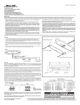
WIRING
OPERATION
12-24VDC
FP#19~28 will aways operate in dual color.
# Inverted color mode.
*Actual approval will be based on the model ordered.
** For use with external flash controller
To Chassis Ground:............................................. BLACK
To+VDC for Warning Mode (fuse @ 1A):.....
RED+WHITE
Default Color Mode - Color 1 alt. 2
(Order Precedence : Mode > Mode or Mode)
To+VDC for Warning Mode (fuse @ 1A):.................. RED
Default Color Mode - Color 1
To+VDC for Warning Mode (fuse @ 1A):.............. WHITE
Default Color Mode - Color 2
For Synchronization and Flash Pattern:.............YELLOW
Connect YELLOW wires of all lightheads together for synchronization.
(All lightheads should be set to the same pattern)
Flash Pattern
1 Double [R65*] Double [SAE]
[SAE]
[SAE]
[SAE]
[SAE]
[2Hz]
[2Hz]
[2Hz]
2 Single
3 Triple
4 Quad
5 Random
6 Steady EF**
7 Single [SAE][CA13]
8
9 Triple
10 Quad
11 Quint
12 Mega
13 Giga
14 Ultra
15 Single-Quad
16 Single H/L
17 Single-Triple-Quint
18 Steady Scene
19 Single-Single
20 Double-Double
21 Triple-Triple Mid
22 Triple-Triple Fast
23 Quint-Triple
24 7-1 Flash
25 7-1 Flash #
26 Quad-Single
27 Quad-Single#
28 Quint-Quint